EP2104175B1 - Nichtwässrige Elektrolyt-Sekundärbatterie, negatives Elektrodenmaterial und Herstellungsverfahren - Google Patents
Nichtwässrige Elektrolyt-Sekundärbatterie, negatives Elektrodenmaterial und Herstellungsverfahren Download PDFInfo
- Publication number
- EP2104175B1 EP2104175B1 EP09250738.3A EP09250738A EP2104175B1 EP 2104175 B1 EP2104175 B1 EP 2104175B1 EP 09250738 A EP09250738 A EP 09250738A EP 2104175 B1 EP2104175 B1 EP 2104175B1
- Authority
- EP
- European Patent Office
- Prior art keywords
- silicon
- negative electrode
- particles
- silicon oxide
- electrode material
- Prior art date
- Legal status (The legal status is an assumption and is not a legal conclusion. Google has not performed a legal analysis and makes no representation as to the accuracy of the status listed.)
- Active
Links
Images


Classifications
-
- H—ELECTRICITY
- H01—ELECTRIC ELEMENTS
- H01M—PROCESSES OR MEANS, e.g. BATTERIES, FOR THE DIRECT CONVERSION OF CHEMICAL ENERGY INTO ELECTRICAL ENERGY
- H01M10/00—Secondary cells; Manufacture thereof
- H01M10/05—Accumulators with non-aqueous electrolyte
- H01M10/052—Li-accumulators
- H01M10/0525—Rocking-chair batteries, i.e. batteries with lithium insertion or intercalation in both electrodes; Lithium-ion batteries
-
- H—ELECTRICITY
- H01—ELECTRIC ELEMENTS
- H01M—PROCESSES OR MEANS, e.g. BATTERIES, FOR THE DIRECT CONVERSION OF CHEMICAL ENERGY INTO ELECTRICAL ENERGY
- H01M4/00—Electrodes
- H01M4/02—Electrodes composed of, or comprising, active material
- H01M4/36—Selection of substances as active materials, active masses, active liquids
- H01M4/58—Selection of substances as active materials, active masses, active liquids of inorganic compounds other than oxides or hydroxides, e.g. sulfides, selenides, tellurides, halogenides or LiCoFy; of polyanionic structures, e.g. phosphates, silicates or borates
-
- H—ELECTRICITY
- H01—ELECTRIC ELEMENTS
- H01M—PROCESSES OR MEANS, e.g. BATTERIES, FOR THE DIRECT CONVERSION OF CHEMICAL ENERGY INTO ELECTRICAL ENERGY
- H01M10/00—Secondary cells; Manufacture thereof
- H01M10/05—Accumulators with non-aqueous electrolyte
-
- H—ELECTRICITY
- H01—ELECTRIC ELEMENTS
- H01M—PROCESSES OR MEANS, e.g. BATTERIES, FOR THE DIRECT CONVERSION OF CHEMICAL ENERGY INTO ELECTRICAL ENERGY
- H01M4/00—Electrodes
- H01M4/02—Electrodes composed of, or comprising, active material
-
- H—ELECTRICITY
- H01—ELECTRIC ELEMENTS
- H01M—PROCESSES OR MEANS, e.g. BATTERIES, FOR THE DIRECT CONVERSION OF CHEMICAL ENERGY INTO ELECTRICAL ENERGY
- H01M4/00—Electrodes
- H01M4/02—Electrodes composed of, or comprising, active material
- H01M4/04—Processes of manufacture in general
-
- H—ELECTRICITY
- H01—ELECTRIC ELEMENTS
- H01M—PROCESSES OR MEANS, e.g. BATTERIES, FOR THE DIRECT CONVERSION OF CHEMICAL ENERGY INTO ELECTRICAL ENERGY
- H01M4/00—Electrodes
- H01M4/02—Electrodes composed of, or comprising, active material
- H01M4/04—Processes of manufacture in general
- H01M4/0402—Methods of deposition of the material
- H01M4/0421—Methods of deposition of the material involving vapour deposition
- H01M4/0428—Chemical vapour deposition
-
- H—ELECTRICITY
- H01—ELECTRIC ELEMENTS
- H01M—PROCESSES OR MEANS, e.g. BATTERIES, FOR THE DIRECT CONVERSION OF CHEMICAL ENERGY INTO ELECTRICAL ENERGY
- H01M4/00—Electrodes
- H01M4/02—Electrodes composed of, or comprising, active material
- H01M4/13—Electrodes for accumulators with non-aqueous electrolyte, e.g. for lithium-accumulators; Processes of manufacture thereof
- H01M4/134—Electrodes based on metals, Si or alloys
-
- H—ELECTRICITY
- H01—ELECTRIC ELEMENTS
- H01M—PROCESSES OR MEANS, e.g. BATTERIES, FOR THE DIRECT CONVERSION OF CHEMICAL ENERGY INTO ELECTRICAL ENERGY
- H01M4/00—Electrodes
- H01M4/02—Electrodes composed of, or comprising, active material
- H01M4/13—Electrodes for accumulators with non-aqueous electrolyte, e.g. for lithium-accumulators; Processes of manufacture thereof
- H01M4/139—Processes of manufacture
- H01M4/1395—Processes of manufacture of electrodes based on metals, Si or alloys
-
- H—ELECTRICITY
- H01—ELECTRIC ELEMENTS
- H01M—PROCESSES OR MEANS, e.g. BATTERIES, FOR THE DIRECT CONVERSION OF CHEMICAL ENERGY INTO ELECTRICAL ENERGY
- H01M4/00—Electrodes
- H01M4/02—Electrodes composed of, or comprising, active material
- H01M4/36—Selection of substances as active materials, active masses, active liquids
- H01M4/362—Composites
- H01M4/364—Composites as mixtures
-
- H—ELECTRICITY
- H01—ELECTRIC ELEMENTS
- H01M—PROCESSES OR MEANS, e.g. BATTERIES, FOR THE DIRECT CONVERSION OF CHEMICAL ENERGY INTO ELECTRICAL ENERGY
- H01M4/00—Electrodes
- H01M4/02—Electrodes composed of, or comprising, active material
- H01M4/36—Selection of substances as active materials, active masses, active liquids
- H01M4/362—Composites
- H01M4/366—Composites as layered products
-
- H—ELECTRICITY
- H01—ELECTRIC ELEMENTS
- H01M—PROCESSES OR MEANS, e.g. BATTERIES, FOR THE DIRECT CONVERSION OF CHEMICAL ENERGY INTO ELECTRICAL ENERGY
- H01M4/00—Electrodes
- H01M4/02—Electrodes composed of, or comprising, active material
- H01M4/36—Selection of substances as active materials, active masses, active liquids
- H01M4/38—Selection of substances as active materials, active masses, active liquids of elements or alloys
- H01M4/386—Silicon or alloys based on silicon
-
- H—ELECTRICITY
- H01—ELECTRIC ELEMENTS
- H01M—PROCESSES OR MEANS, e.g. BATTERIES, FOR THE DIRECT CONVERSION OF CHEMICAL ENERGY INTO ELECTRICAL ENERGY
- H01M4/00—Electrodes
- H01M4/02—Electrodes composed of, or comprising, active material
- H01M4/36—Selection of substances as active materials, active masses, active liquids
- H01M4/48—Selection of substances as active materials, active masses, active liquids of inorganic oxides or hydroxides
- H01M4/483—Selection of substances as active materials, active masses, active liquids of inorganic oxides or hydroxides for non-aqueous cells
-
- H—ELECTRICITY
- H01—ELECTRIC ELEMENTS
- H01M—PROCESSES OR MEANS, e.g. BATTERIES, FOR THE DIRECT CONVERSION OF CHEMICAL ENERGY INTO ELECTRICAL ENERGY
- H01M4/00—Electrodes
- H01M4/02—Electrodes composed of, or comprising, active material
- H01M4/62—Selection of inactive substances as ingredients for active masses, e.g. binders, fillers
- H01M4/621—Binders
- H01M4/622—Binders being polymers
-
- H—ELECTRICITY
- H01—ELECTRIC ELEMENTS
- H01M—PROCESSES OR MEANS, e.g. BATTERIES, FOR THE DIRECT CONVERSION OF CHEMICAL ENERGY INTO ELECTRICAL ENERGY
- H01M4/00—Electrodes
- H01M4/02—Electrodes composed of, or comprising, active material
- H01M4/62—Selection of inactive substances as ingredients for active masses, e.g. binders, fillers
- H01M4/624—Electric conductive fillers
- H01M4/625—Carbon or graphite
-
- Y—GENERAL TAGGING OF NEW TECHNOLOGICAL DEVELOPMENTS; GENERAL TAGGING OF CROSS-SECTIONAL TECHNOLOGIES SPANNING OVER SEVERAL SECTIONS OF THE IPC; TECHNICAL SUBJECTS COVERED BY FORMER USPC CROSS-REFERENCE ART COLLECTIONS [XRACs] AND DIGESTS
- Y02—TECHNOLOGIES OR APPLICATIONS FOR MITIGATION OR ADAPTATION AGAINST CLIMATE CHANGE
- Y02E—REDUCTION OF GREENHOUSE GAS [GHG] EMISSIONS, RELATED TO ENERGY GENERATION, TRANSMISSION OR DISTRIBUTION
- Y02E60/00—Enabling technologies; Technologies with a potential or indirect contribution to GHG emissions mitigation
- Y02E60/10—Energy storage using batteries
Definitions
- This invention generally relates to non-aqueous electrolyte secondary batteries, typically lithium ion secondary batteries. Specifically, it relates to negative electrode materials for use in such batteries and more particularly, to negative electrode materials comprising silicon oxide and silicon as an active material, and negative electrodes made thereof.
- JP 3008228 and JP 3242751 disclose negative electrode materials comprising oxides of B, Ti, V, Mn, Co, Fe, Ni, Cr, Nb, and Mo and composite oxides thereof.
- Other negative electrode materials are known as comprising silicon oxide ( JP 2997741 ), and Si 2 N 2 O, Ge 2 N 2 O or Sn 2 N 2 O ( JP 3918311 ).
- Silicon is regarded most promising in attaining the battery's goals of size reduction and capacity enhancement since it exhibits an extraordinarily high theoretical capacity of 4,200 mAh/g as compared with the theoretical capacity 372 mAh/g of carbonaceous materials that are currently used in commercial batteries. Silicon is known to take various forms of different crystalline structure depending on their preparation.
- JP 2964732 discloses a lithium ion secondary battery using single crystal silicon as a support for negative electrode active material.
- JP 3079343 discloses a lithium ion secondary battery using a lithium alloy Li x Si (0 ⁇ x ⁇ 5) with single crystal silicon, polycrystalline silicon or amorphous silicon.
- the lithium alloy Li x Si with amorphous silicon is preferred, which is prepared by coating crystalline silicon with amorphous silicon resulting from plasma decomposition of monosilane, followed by grinding.
- the negative electrode material therein uses 30 parts of a silicon component and 55 parts of graphite as the conductive agent as described in Example, failing to take full advantage of the potential battery capacity of silicon.
- JP-A 2000-243396 teaches mechanical alloying of a metal oxide such as silicon oxide with graphite and subsequent carbonization; JP-A 2000-215887 mentions coating of Si particles on their surface with a carbon layer by chemical vapor deposition; and JP-A 2002-42806 proposes coating of silicon oxide particles on their surface with a carbon layer by chemical vapor deposition.
- the provision of particle surfaces with a carbon layer improves conductivity, but is not successful in overcoming the outstanding problems of silicon negative electrodes, i.e., in mitigating substantial volumetric changes associated with charge/discharge cycles or in preventing electricity collection and cycle performance from degrading.
- Means for mitigating volume expansion by tailoring the layer structure of silicon active material are also disclosed, for example, disposition of two layers of silicon negative electrode ( JP-A 2005-190902 ), and coating or encapsulating with carbon or another metal and oxide for restraining particles from spalling off ( JP-A 2005-235589 , JP-A 2006-216374 , JP-A 2006-236684 , JP-A 2006-339092 , JP 3622629 , JP-A 2002-75351 , and JP 3622631 ).
- JP-A 2006-338996 In the method of gas phase growing silicon directly on a current collector, degradation of cycle performance due to volume expansion can be restrained by controlling the growth direction ( JP-A 2006-338996 ).
- the method of enhancing the cycle performance of negative electrode material by coating silicon surfaces with carbon to be electrically conductive or coating silicon with an amorphous metal layer as mentioned above utilizes only about a half of the silicon's own battery capacity. There is a desire for a higher capacity. As for the polycrystalline silicon having grain boundaries, the disclosed method is difficult to control the cooling rate and hence, to reproduce consistent physical properties.
- silicon oxide is represented by SiOx wherein x is slightly greater than the theory of 1 due to oxide coating, and is found on X-ray diffractometry analysis to have the structure that amorphous silicon ranging from several to several tens of nanometers is finely dispersed in silica.
- the battery capacity of silicon oxide is smaller than that of silicon, but greater than that of carbon by a factor of 5 to 6 on a weight basis. Silicon oxide experiences a relatively less volume expansion. Silicon oxide is thus believed ready for use as the negative electrode active material. Nevertheless, silicon oxide has a substantial irreversible capacity and a very low initial efficiency of about 70%, which requires an extra battery capacity of the positive electrode when a battery is actually fabricated. Then an increase of battery capacity corresponding to the 5 to 6-fold capacity increase per active material weight is not expectable.
- the problem of silicon oxide to be overcome prior to practical use is a substantially low initial efficiency. This may be overcome by making up the irreversible fraction of capacity or by restraining the irreversible capacity.
- the method of making up the irreversible fraction of capacity by previously doping silicon oxide with Li metal is reported effective.
- Doping of lithium metal may be carried out by attaching a lithium foil to a surface of negative electrode active material ( JP-A 11-086847 ) or by vapor depositing lithium on a surface of negative electrode active material ( JP-A 2007-122992 ).
- a thin lithium foil that matches with the initial efficiency of silicon oxide negative electrode is hardly available or prohibitively expensive if available.
- the deposition of lithium vapor makes the fabrication process complex and is impractical.
- silicon Aside from lithium doping, it is also disclosed to enhance the initial efficiency of negative electrode by increasing a weight proportion of silicon.
- One method is by adding silicon particles to silicon oxide particles to reduce the weight proportion of silicon oxide ( JP 3982230 ).
- silicon vapor is generated and precipitated in the same stage as is produced silicon oxide, obtaining mixed solids of silicon and silicon oxide ( JP-A 2007-290919 ).
- Silicon has both a high initial efficiency and a high battery capacity as compared with silicon oxide, but displays a percent volume expansion as high as 400% upon charging.
- EP-A-1363341 describes negative electrode materials containing composite particles having a structure in which crystallites of silicon are dispersed in silicon dioxide. These composite particles may be coated on their surfaces with carbon.
- JP-A-2004/139886 also discloses composite particles, but this time made from a mixture of carbon, silicon and silicon oxide particles by milling and then optionally coated with further carbon e.g. by calcining an organic compound or by CVD.
- JP-A-2005/243431 describes a negative electrode active material obtained by coating SiO particles with a carbon material.
- JP-A-2007/294423 (corresponding to US2007/0224508A ) describes a silicon-silicon oxide-lithium composite, to make which silicon grains are dispersed in silicon oxide, the silicon-silicon oxide composite then being doped with lithium.
- WO2007/114168 describes methods for making polycrystalline silicon for use in negative electrode materials.
- the silicon-based active material still has a problem to be solved prior to practical use, independent of whether it is based on a metal element or an oxide thereof.
- a negative electrode active material which can restrain the volumetric change associated with occlusion and release of lithium, mitigate a lowering of conductivity due to atomization by fissure of particles and separation of particles from the current collector, be manufactured on a mass scale at a low cost, and comply with the application as in mobile phones where repetitive cycle performance is of high priority.
- An object herein is to provide new and useful negative electrode materials suitable for non-aqueous electrolyte secondary batteries, comprising silicon oxide particles as an active material.
- Preferred properties are a high 1st cycle charge/discharge efficiency and good or improved cycle performance, while maintaining the high battery capacity and low volume expansion characteristic of silicon oxide.
- Other aspects are methods of preparation of such materials, negative electrodes made using such material and a non-aqueous electrolyte secondary battery using the same.
- the inventors made efforts to search for a negative electrode active material which has a high battery capacity surpassing carbonaceous materials, minimizes a change of volume expansion inherent to silicon, overcomes silicon oxide's drawback of a low 1st cycle charge/discharge efficiency, and has a high initial charge/discharge efficiency.
- the inventors have found that outstanding problems can be addressed by using both specific coated silicon oxide particles having a graphite coating and 1 to 50 wt% of silicon particles as the active material.
- silicon is added to graphite-coated silicon oxide particles, a volume expansion in excess of 400% as often found with ordinary silicon is not observed, and a percent volume expansion is maintained at a level approximately equal to that of silicon oxide. This leads to an increased battery capacity per volume.
- the conductivity can be improved by addition or coating of a conductive agent.
- the conductivity and initial charge/discharge efficiency are improved by coating of graphite, and 1 to 20 wt% of a binder is compounded in the negative electrode material to prevent it from being broken or powdered by repetition of expansion and contraction on charge/discharge cycles, then the electrode itself does not experience a loss of conductivity.
- a non-aqueous electrolyte secondary battery having improved cycle performance is fabricated. The invention is predicated on this finding.
- the conductivity can be improved by addition or coating of a conductive agent.
- the conductivity is also improved by vapor deposition of carbon.
- the invention provides a negative electrode material, a method for the preparation thereof, a negative electrode, and a non-aqueous electrolyte secondary battery, defined below.
- a first aspect is a negative electrode material for non-aqueous electrolyte secondary batteries, comprising an active material and 1 to 20% by weight of a binder, said active material comprising:
- the silicon oxide particles may be prepared by heating a mixture of silicon dioxide and metallic silicon under vacuum at a temperature of 1,000 to 1,500°C to produce a silicon oxide gas and letting the silicon oxide gas to precipitate at a temperature of 500 to 1,100°C.
- the silicon particles may be silicon particles coated on their surface with a graphite coating.
- the polycrystalline silicon particles may have a true specific gravity of 2.300 to 2.320.
- the polycrystalline silicon particles may be prepared by pyrolysis of a silane gas at a temperature of up to 1,000°C. This may be particulate polycrystalline silicon prepared by pyrolysis of the silane gas in a fluidized bed.
- the silane gas may be a silane or chlorosilane.
- the polycrystalline silicon particles may have a median diameter D 50 of 0.1 to 20 ⁇ m.
- the binder may comprise a polyimide resin.
- Another aspect is a negative electrode for a non-aqueous electrolyte secondary battery, comprising a negative electrode material as described.
- the electrode may experience volumetric change by a factor of less than 2 before and after charging.
- non-aqueous electrolyte secondary battery comprising the negative electrode, a positive electrode, a separator and a non-aqueous electrolyte. It may be a lithium ion secondary battery.
- a method for preparing the negative electrode material may comprise the steps of (I) effecting chemical vapor deposition of an organic gas and/or vapor on silicon oxide particles under a vacuum of 50 to 30,000 Pa at 600 to 1,100°C to coat surfaces of the silicon oxide particles with a graphite coating, and (II) combining the coated silicon oxide particles resulting from step (I) with silicon particles and a binder.
- the silicon oxide particles and the coated silicon oxide particles may be kept in an atmosphere at up to 1,100°C.
- the disclosure herein includes a method of preparing a negative electrode material according to any one of the above proposals comprising combining the specific components thereof and optionally comprising preliminarily preparing said silicon oxide particles and/or said silicon particles.
- the negative electrode for non-aqueous electrolyte secondary batteries as proposed herein can have good or improved cycle performance while maintaining the high battery capacity and low volume expansion of silicon oxide.
- a negative electrode material comprising silicon oxide and silicon as the active material and a polyimide resin as the binder is found to be well adherent to current collectors.
- the corresponding batteries are found to have high initial efficiency and to maintain improved performance and efficiency over repeated charge/discharge cycles by virtue of mitigated volumetric changes during charge/discharge cycles.
- conductive or “conductivity” refers to electrically conductive or electric conductivity.
- the negative electrode material for non-aqueous electrolyte secondary batteries comprises an active material and a binder.
- the active material comprises silicon oxide particles and silicon particles.
- the silicon particles are present in an amount of not more than 50% by weight based on the active material.
- the binder is present in an amount of 1 to 20% by weight based on the negative electrode material.
- silicon oxide generally refers to amorphous silicon oxides which are produced by heating a mixture of silicon dioxide and metallic silicon to produce silicon oxide gas and cooling the gas for precipitation.
- Silicon oxide is represented by the general formula SiOx wherein x is in the range: 1.0 s x ⁇ 1.6.
- the mixture contains silicon dioxide and metallic silicon in a molar ratio of approximately 1:1.
- When the mixture is heated under reduced pressure at 1,000 to 1,500°C, preferably 1,100 to 1,500°C, it produces silicon oxide gas.
- the gas is led into a precipitating chamber at 500 to 1,100°C where silicon oxide is solidified and collected.
- x is in the range: 1.0 ⁇ x ⁇ 1.2.
- the silicon oxide thus produced is ground into particles prior to use.
- the particle size distribution may be measured by the laser diffraction scattering method.
- a powder sample of particles having a total volume of 100% is analyzed to draw a cumulative curve, and the particle size at 10%, 50%, and 90% on the cumulative curve is designated 10% diameter, 50% diameter, and 90% diameter (in ⁇ m), respectively.
- Evaluation is made herein on the basis of 50% diameter which is a 50% cumulative diameter or median diameter D 50 .
- the powder should preferably have a median diameter D 50 of 0.1 ⁇ m to 50 ⁇ m and more preferably 1 ⁇ m to 20 ⁇ m. Outside the range, a smaller median diameter corresponds to a larger specific surface area which may lead to a lower negative electrode film density whereas particles with a larger median diameter may penetrate through a negative electrode film, causing short-circuits.
- any well-known grinding machine may be used in combination with a classifier.
- Use may be made of, for example, a ball mill and media agitating mill in which grinding media such as balls or beads are brought in motion and the charge (to be ground) is ground by utilizing impact forces, friction forces or compression forces generated by the kinetic energy; a roller mill in which grinding is carried out by compression forces generated between rollers; a jet mill in which the charge is impinged against the liner or each other at a high speed, and grinding is carried out by impact forces generated by impingement; a hammer mill, pin mill and disc mill in which a rotor with hammers, blades or pins attached thereto is rotated and the charge is ground by impact forces generated by rotation; a colloid mill utilizing shear forces; and a wet, high pressure, counter-impingement dispersing machine "Ultimizer” (Sugino Machine Ltd.).
- Either wet or dry grinding may be employed.
- the grinding may be followed by dry, wet or sieve classification in order to gain a proper particle size distribution.
- the dry classification generally uses a gas stream and includes successive or simultaneous steps of dispersion, separation (segregation between fine and coarse particles), collection (separation between solid and gas), and discharge.
- pretreatment adjustment of water content, dispersibility, humidity or the like
- An integrated type of dry grinder/classifier may also be used which can conduct grinding and classifying operations at a time to deliver an output of the desired particle size distribution.
- silicon oxide particles which have been ground to the predetermined particle size, carbon is deposited by chemical vapor deposition (CVD). It is noted that the silicon oxide particles prior to carbon coating are sometimes referred to as "neat particles" to distinguish them from the coated particles.
- CVD chemical vapor deposition
- an area ratio S -84 /S -110 is in the range 0.5 ⁇ S -84 /S -110 ⁇ 1.1, preferably between 0.6 and 1.0, and more preferably between 0.6 and 0.8.
- amorphous silicon oxide normally exhibits only a broad peak centering around -110 ppm while a peak characteristic of Si diamond crystals is detected around -84 ppm due to thermal hysteresis. That is, a smaller area centering the signal attributable to Si diamond crystals is preferred.
- the coated silicon oxide particles are silicon oxide particles coated on their surface with a graphite coating. It is important to select the type of graphite enclosing surfaces of silicon oxide particles and control the proportion thereof within a certain range. On Raman spectroscopy analysis, the graphite coating exhibits scattering peaks having an intensity I 1330 and I 1580 at 1330 cm -1 and 1580 cm -1 . Herein an intensity ratio I 1330 /I 1580 is in the range 1.5 ⁇ I 1330 /I 1580 ⁇ 3.0.
- graphitic materials are classified into three allotropies, diamond, graphite, and amorphous carbon. These graphitic materials have their own physical properties.
- diamond has a high strength, high density and high insulation, and graphite has good electrical conductivity.
- a graphitic material having diamond structure and a graphitic material having graphite structure are mixed in an optimum proportion so as to gain an optimum combination of the respective characteristics, resulting in a negative electrode material capable of preventing failure by expansion and contraction during charge/discharge cycles and having a conductive network.
- the proportion of the graphitic material having diamond structure and the graphitic material having graphite structure may be determined by Raman spectroscopy analysis, i.e., on the basis of a Raman spectrum. More specifically, since diamond develops a sharp peak at 1330 cm -1 Raman shift and graphite develops a sharp peak at 1580 cm -1 Raman shift, the proportion of the two graphitic components may be simply determined from a ratio of peak intensities.
- the inventors have found that when silicon oxide having a graphite coating which on Raman spectroscopy analysis, develops a scattering peak having an intensity I 1330 at 1330 cm -1 Raman shift and a scattering peak having an intensity I 1580 at 1580 cm -1 Raman shift, wherein an intensity ratio I 1330 /I 1580 is in the range: 1.5 ⁇ I 1330 /I 1580 ⁇ 3.0, and preferably 1.7 ⁇ I 1330 /I 1580 ⁇ 2.5 is used as a lithium ion secondary battery negative electrode material, a lithium ion secondary battery having satisfactory battery performance is obtained.
- the graphite coating may have a reduced strength so that electrode failure may occur due to expansion and contraction of electrode material during charge/discharge cycles, leading to a lowering of battery capacity and degradation of cycle performance on repeated use. If the proportion of diamond structure material is so high as to provide an intensity ratio I 1330 /I 1580 equal to or more than 3.0, there may result a loss of conductivity and degradation of cycle performance.
- the coated silicon oxide particles (which is coated with graphite having the specific Raman spectroscopy intensity ratio) may be prepared, for example, by subjecting surfaces of silicon oxide particles to CVD in an organic gas and/or vapor under a reduced pressure of 50 to 30,000 Pa at a temperature of 600 to 1,100°C.
- the reduced pressure is preferably 100 to 20,000 Pa, and more preferably 1,000 to 20,000 Pa.
- Under a pressure of lower than 50 Pa there results a graphitic material having a higher proportion of diamond structure, which may lead to losses of conductivity and cycle performance when used as a lithium ion secondary battery negative electrode.
- the CVD temperature is preferably 800 to 1,050°C. A temperature below 600°C may require a longer time of treatment. If the treatment temperature is above 1,100°C, particles may be fused and agglomerated together during CVD and hence, a conductive coating may not be formed at the agglomerated interface, resulting in a negative electrode material having poor cycle performance. Additionally, disproportionation reaction of silicon oxide may take place, leading to a signal area ratio in excess of 1.1 on solid NMR analysis.
- the treatment time may be determined as appropriate depending on the graphite buildup, treatment temperature, and the concentration (or flow velocity) and quantity of organic gas. Usually a treatment time of 1 to 10 hours, especially 2 to 7 hours is employed for efficiency and economy.
- the coated silicon oxide particles thus obtained have the structure having silicon fine-grains dispersed in a silicon oxide.
- the buildup (or coating weight) of graphite is preferably 1 to 50%, and more preferably 5 to 20% by weight based on the coated silicon oxide particles, but not particularly limited thereto. Outside the range, a larger buildup of carbon may detract from the battery capacity characteristic of silicon oxide whereas a smaller buildup may lead to inconsistent carbon coatings and fail to provide a sufficient conductivity.
- the organic material to generate the organic gas is selected from those materials capable of producing carbon (graphite) through pyrolysis at the heat treatment temperature, especially in a non-oxidizing atmosphere.
- exemplary are hydrocarbons such as methane, ethane, ethylene, acetylene, propane, butane, butene, pentane, isobutane, and hexane alone or in admixture of any, and monocyclic to tricyclic aromatic hydrocarbons such as benzene, toluene, xylene, styrene, ethylbenzene, diphenylmethane, naphthalene, phenol, cresol, nitrobenzene, chlorobenzene, indene, coumarone, pyridine, anthracene, and phenanthrene alone or in admixture of any.
- gas light oil, creosote oil and anthracene oil obtained from the tar distillation step are useful as well
- the coated silicon oxide particles having the specific intensity and area ratios preferably have an average particle size of 0.1 to 50 ⁇ m, and more preferably 1 to 20 ⁇ m, like the neat silicon oxide particles. Note that the average particle size is determined by measurement of particle size distribution by laser diffraction scattering method, like the neat silicon oxide particles.
- the coated silicon oxide particles having the specific intensity and area ratios are preferably present in an amount of 50 to 99%, more preferably 70 to 95%, and even more preferably 70 to 90% by weight based on the active material.
- silicon is divided into single crystal silicon, polycrystalline silicon, and amorphous silicon in terms of crystallinity, and into chemical grade silicon (often referred to as metallic silicon) and metallurgical grade silicon in terms of purity.
- single crystal silicon and polycrystalline silicon are preferred because of a high purity, with the polycrystalline silicon being more preferred.
- the polycrystalline silicon consists of partially ordered crystals.
- the amorphous silicon differs in that it assumes a substantially disordered arrangement of silicon atoms having a network structure, but may be used because amorphous silicon can be transformed into polycrystalline silicon by heat aging.
- polycrystalline silicon may be prepared by melting metallic silicon and directionally solidifying the melt, for thereby causing segregation of impurities and increasing the purity, or by quenching the metallic silicon melt.
- These polycrystalline silicon products are advantageously used because they are mostly less expensive than polycrystalline silicon products prepared from monosilane and chlorosilane. Even the chemical grade silicon having a low purity may be used as an inexpensive reactant because impurities such as aluminum, iron and calcium can be dissolved away by acid treatment.
- Polycrystalline silicon consists of relatively large crystal grains of different orientation defining boundaries therebetween. As described in Complete Series of Inorganic Chemistry, Vol. XII-2, Silicon (Maruzen Co., Ltd.), p184 , polycrystalline silicon can be synthesized from trichlorosilane or monosilane.
- the current mainstream processes for producing polycrystalline silicon in an industrial manner are the Siemens process and Komatsu-ASiMI process involving pyrolysis of trichlorosilane or monosilane in a precipitating reactor (or bell jar) and depositing in a silicon rod form.
- the ethyl process involving using a fluidized bed reactor and growing polycrystalline silicon on surfaces of silicon particles is also available.
- Polycrystalline silicon may also be prepared by melting metallic silicon and directionally solidifying the melt, for thereby causing segregation of impurities and increasing the purity, or by quenching the silicon melt. It is known that polycrystalline silicon products thus synthesized differ in conductivity and residual strain depending on the size and orientation of crystal grains.
- the polycrystalline silicon which is particularly useful herein is one produced through pyrolysis of a silane gas (i.e., silane or chlorosilane) in a relatively low temperature range of up to 1,000°C, and crystal growth.
- a silane gas i.e., silane or chlorosilane
- the production processes used herein include the Siemens, Komatsu-ASiMI, and ethyl processes, mentioned above.
- the Siemens and Komatsu-ASiMI processes are batchwise in that polycrystalline silicon is precipitated on a surface of a silicon rod. Because polycrystalline silicon growing on the rod surface undergoes recrystallization, relatively large crystal grains are likely to form.
- the ethyl process using a fluidized bed reactor is characterized by a high productivity, effective gas-solid heat transfer, and a uniform heat distribution within the reactor because polycrystalline silicon is grown on particle surfaces so that a large specific surface area is available for reaction. Since polycrystalline silicon particles growing to a particular particle size corresponding to the linear velocity of the fluidized layer are discharged from within the reactor, continuous reaction is possible. Since the growth of crystallites is slow, relatively small crystal grains are formed.
- Examples of the silane or chlorosilane used in the production processes described above include monosilane, disilane, monochlorosilane, dichlorosilane, trichlorosilane and tetrachlorosilane.
- the growth temperature of polycrystalline silicon on a rod is around 850°C when monosilane is used and around 1,100°C when trichlorosilane is used. Preference is given to monosilane and dichlorosilane which can be decomposed at temperatures below 1,000°C.
- the fluidized bed process using monosilane employs a further lower temperature of 600 to 800°C, the process is typically carried out around 650°C because operation at higher temperatures causes fine particles to form as a result of decomposition and growth in the vapor phase.
- the use of monosilane or dichlorosilane as reactant gas enables to maintain the reactor at a relatively low temperature, and the use of a fluidized bed reactor as the reaction system enables to reduce the residence time within the fluidized bed and to slow down the crystal growth of polycrystalline silicon being deposited. As a result, fully densified crystal grains are formed, and fine voids are defined between crystal grains being deposited one on another. It is believed that these fine voids function to mitigate the volume expansion and restrain cleavage upon charging.
- Crystallites of polycrystalline silicon produced from monosilane for the most part, have a size of 20 to 34 nm, while crystallites produced from trichlorosilane have a size of 35 to 40 nm, with an increase of crystallite size being observed.
- crystallites of metallic silicon and polycrystalline silicon produced by directional solidification, quenching and hot plastic working processes have a size of 40 to 45 nm, which is undesired for the non-aqueous electrolyte secondary battery application contemplated herein.
- the polycrystalline silicon produced in the fluidized bed reactor has a specific gravity of 2.300 to 2.320, which is very low as compared with single crystal silicon, implying a rather amorphous crystal structure.
- polycrystalline silicon produced from trichlorosilane by the Siemens process polycrystalline silicon produced from monosilane by the Komatsu-ASiMI process
- metallic silicon have a specific gravity in the range of 2.320 to 2.340, which is substantially equal to single crystal silicon, implying a densified crystal structure within particles.
- the polycrystalline silicon produced by the aforementioned process has chemically bonded hydrogen atoms. Its silicon purity can be improved typically by heat treatment at 1,000 to 1,200°C for a brief time of 2 to 4 hours.
- the hydrogen content which is normally about 600 to 1,000 ppm prior to the heat treatment may be reduced to or below 30 ppm by the heat treatment.
- Preferred for use in the negative electrode material is polycrystalline silicon which has been purified to a hydrogen content of up to 30 ppm by heat treatment.
- silicon particles may be coated with carbon.
- Deposition of carbon improves conductivity, with improvements in cycle performance and battery capacity being expectable.
- the buildup (or coating weight) of carbon is preferably 0.1 to 20% and more preferably 1 to 10% by weight of the carbon-coated polycrystalline silicon particles.
- the polycrystalline silicon is ground to the desired particle size prior to use. Grinding may be performed as described for the silicon oxide.
- the silicon powder should preferably have a median diameter D 50 of 0.1 ⁇ m to 50 ⁇ m and more preferably 0.1 ⁇ m to 10 ⁇ m. Too large a particle size may have a tendency to increase volume expansion. The particle size measurement is the same as described for the silicon oxide particles.
- Silicon oxide particles combined with polycrystalline silicon particles can be used as the active material for non-aqueous electrolyte secondary battery negative electrodes.
- This combination has many advantages including a high capacity as compared with the currently used graphite and carbonaceous materials, a high initial efficiency as compared with silicon oxide alone, controlled volumetric changes associated with charge/discharge cycles as compared with silicon itself, and improved adhesion between particles and the binder. This ensures fabrication of a non-aqueous electrolyte secondary battery, especially lithium ion secondary battery, having improved cycle performance.
- silicon particles are present in an amount of not more than 50%, preferably 1 to 50%, more preferably 5 to 30%, and even more preferably 10 to 30% by weight. Less than 1 wt% of silicon particles may be too small to exert the effect of improving initial efficiency whereas an active material containing more than 50 wt% of silicon particles may be difficult to maintain a percent volume expansion.
- the active material may be present in an amount of 50 to 98%, more preferably 75 to 96%, and even more preferably 80 to 96% by weight based on the negative electrode material.
- a binder is used in the negative electrode material.
- the binder is preferably selected from polyimide resins, especially aromatic polyimide resins.
- the aromatic polyimide resin binder has good solvent resistance, and may comply with a volume expansion associated with charge/discharge cycles to prevent peeling of the negative electrode from the current collector and separation of the active material.
- the resultant negative electrode has improved bond to the current collector and ensures fabrication of a non-aqueous electrolyte secondary battery which has a high initial charge/discharge efficiency, mitigated volumetric changes associated with charge/discharge cycles, improved performance and efficiency over repeated charge/discharge cycles.
- the binder may be used alone or in admixture of two or more.
- aromatic polyimide resins are generally difficultly soluble in organic solvents and must not be swollen or dissolved in electrolytic solution. In general, aromatic polyimide resins are soluble only in high-boiling organic solvents, for example, cresol.
- an electrode paste may be prepared by adding a polyamic acid, polyimide precursor which is relatively easily soluble in many organic solvents such as dimethylformamide, dimethylacetamide, N-methylpyrrolidone, ethyl acetate, acetone, methyl ethyl ketone, methyl isobutyl ketone, and dioxolan, and heat treating at a temperature of at least 300° C for a long time for thereby effecting dehydration and imidization, thus forming a polyimide binder.
- organic solvents such as dimethylformamide, dimethylacetamide, N-methylpyrrolidone, ethyl acetate, acetone, methyl ethyl ketone, methyl is
- Suitable aromatic polyimide resins are those having a basic skeleton derived from tetracarboxylic dianhydrides and diamines.
- Suitable tetracarboxylic dianhydrides include aromatic tetracarboxylic dianhydrides such as pyromellitic dianhydride, benzophenonetetracarboxylic dianhydride and biphenyltetracarboxylic dianhydride, alicyclic tetracarboxylic dianhydrides such as cyclobutanetetracarboxylic dianhydride, cyclopentanetetracarboxylic dianhydride and cyclohexanetetracarboxylic dianhydride, and aliphatic tetracarboxylic dianhydrides such as butanetetracarboxylic dianhydride, alone or in admixture.
- Suitable diamines include aromatic, alicyclic and aliphatic diamines such as, for example, p-phenylene diamine, m-phenylene diamine, 4,4'-diaminodiphenylmethane, 4,4'-diaminodiphenyl ether, 2,2'-diaminodiphenylpropane, 4,4'-diaminodiphenyl sulfone, 4,4'-diaminobenzophenone, 2,3-diaminonaphthalene, 1,3-bis(4-aminophenoxy)benzene, 1,4-bis(4-aminophenoxy)benzene, 4,4'-di(4-aminophenoxy)diphenyl sulfone, 2,2'-bis[4-(4-aminophenoxy)phenyl]propane, alone or in admixture.
- aromatic diamines such as, for example, p-phenylene diamine,
- Synthesis of polyamic acid intermediate is generally carried out by a solution polymerization process.
- the process uses a solvent such as N,N'-dimethylformamide, N,N'-dimethylacetamide, N-methyl-2-pyrrolidone, N-methylcaprolactam, dimethyl sulfoxide, tetramethyl urea, pyridine, dimethyl sulfone, hexamethylphosphoramide, and butyrolactone, alone or in admixture.
- the reaction temperature is generally in the range of -20° C to 150° C, and preferably -5°C to 100° C.
- the polyamic acid intermediate is converted into a polyimide resin typically by heating to induce dehydration and cyclization. Heating for dehydration and cyclization may be at any temperature in the range of 140 to 400°C and preferably 150 to 250°C.
- the time taken for dehydration and cyclization is 30 seconds to 10 hours, and preferably 5 minutes to 5 hours, depending on the heating temperature.
- polyimide resin polyimide resins in powder form and solutions of polyimide precursors in N-methylpyrrolidone are commercially available. Examples include U-Varnish A, U-Varnish S, UIP-R and UIP-S from Ube Industries Ltd., Kayaflex KPI-121 from Nippon Kayaku Co., Ltd., and Rikacoat SN-20, PN-20 and EN-20 from New Japan Chemical Co., Ltd.
- the binder is present in an amount of 1 to 20%, and preferably 3 to 15% by weight based on the negative electrode material. Less amounts of the binder may allow the active material to separate apart whereas excessive amounts may reduce the percent voids and increase a dielectric fraction to interfere with migration of lithium ions.
- a conductive agent such as graphite may be added.
- the type of conductive agent used herein is not particularly limited as long as it is an electronically conductive material which does not undergo decomposition or alteration in the battery.
- Illustrative conductive agents include metals in powder or fiber form such as Al, Ti, Fe, Ni, Cu, Zn, Ag, Sn and Si, natural graphite, synthetic graphite, various coke powders, meso-phase carbon, vapor phase grown carbon fibers, pitch base carbon fibers, PAN base carbon fibers, and graphite obtained by firing various resins.
- the conductive agent is preferably used in solvent dispersion form because an electrode paste in which the conductive agent is uniformly distributed and bonded to silicon and silicon oxide particles is obtained by previously dispersing the conductive agent in a solvent such as water or N-methyl-2-pyrrolidone and adding the dispersion to the active material. Any well-known surfactant may be added to help disperse the conductive agent in the solvent.
- the solvent used for conductive agent dispersion is desirably the same as the solvent used for the binder.
- the conductive agent is present in an amount of up to 50% by weight based on the negative electrode material (corresponding to a battery capacity of at least about 1,000 mAh/g of the negative electrode material).
- the amount of conductive agent is preferably 1 to 30%, and more preferably 1 to 10% by weight based on the negative electrode material. If the amount of the conductive agent is too small, the negative electrode material may have a poor conductivity, tending to exhibit a higher initial resistivity. An excessive amount of the conductive agent may lead to a loss of battery capacity.
- carboxymethyl cellulose, sodium polyacrylate, acrylic polymers or fatty acid esters may be added as a viscosity regulator to the negative electrode material.
- the negative electrode material is prepared by combining silicon oxide particles and silicon particles with the binder.
- a mixture of coated silicon oxide particles and silicon particles is previously dispersed in a solvent such as water or N-methyl-2-pyrrolidone before the binder is compounded therein. It is recommended that neat silicon oxide particles and coated silicon oxide particles be kept in an atmosphere at a temperature of up to 1,100°C, more preferably up to 1,050°C throughout the process from the start with neat silicon oxide particles until the completion of negative electrode material.
- a negative electrode may be prepared, for example, by the following procedure.
- the negative electrode (shaped form) is prepared by combining the active material, binder, conductive agent, and additives, kneading them in a solvent suitable for dissolution and dispersion of the binder such as water or N-methylpyrrolidone to form a paste-like mix, and applying the mix in sheet form to a current collector.
- the current collector used herein may be a foil of any material which is commonly used as the negative electrode current collector, for example, a copper or nickel foil while the thickness and surface treatment thereof are not particularly limited.
- the method of shaping or molding the mix into a sheet is not limited, and any well-known method may be used.
- the negative electrode material experiences a volumetric change by a factor of not more than 2 before and after charging, more preferably a volumetric change by a factor of less than 2, even more preferably 1.0 to 1.8, and most preferably 1.0 to 1.6.
- a negative electrode material experiencing such a small volumetric change before and after charging is provided by the negative electrode material of the invention. More specifically, provided that the negative electrode material has a volume V1 prior to charging and a volume V2 after charging, V2 is greater than V1 by a factor of not more than 2 (i.e., V2/V1 ⁇ 2), preferably less than 2. Note that a volumetric change before and after charging is measured according to the procedure "Determination of Battery Properties" in Example to be described later.
- a non-aqueous electrolyte secondary battery may be fabricated from the negative electrode (shaped form) thus obtained.
- a typical secondary battery is a lithium ion secondary battery.
- a further embodiment of the present invention is a secondary battery comprising a positive electrode, a negative electrode, a separator, and a non-aqueous electrolyte, characterized in that the negative electrode comprises the negative electrode material defined herein, that is, the negative electrode (shaped form) constructed as above.
- the other components including positive electrode, separator, electrolytic solution and electrolyte, and the battery shape are not particularly limited.
- the positive electrode active materials include oxides and sulfides which are capable of occluding and releasing lithium ions. They may be used alone or in admixture. Examples include sulfides and oxides of metals excluding lithium such as TiS 2 , MoS 2 , NbS 2 , ZrS 2 , VS 2 , V 2 O 5 , MoO 3 , Mg(V 3 O 8 ) 2 , and lithium and lithium-containing complex oxides. Composite metals such as NbSe 2 are also useful.
- lithium complex oxides based on Li p MetO 2 are preferred wherein Met is preferably at least one element of cobalt, nickel, iron and manganese and p has a value in the range: 0.05 ⁇ p ⁇ 1.10.
- Illustrative examples of the lithium complex oxides include LiCoO 2 , LiNiO 2 , LiFeO 2 , and Li q Ni r Co 1-r O 2 (wherein q and r have values varying with the charged/discharged state of the battery and usually in the range: 0 ⁇ q ⁇ 1 and 0.7 ⁇ r ⁇ 1) having a layer structure, LiMn 2 O 4 having a spinel structure, and rhombic LiMnO 2 .
- a substitutional spinel type manganese compound adapted for high voltage operation which is LiMet s Mn 1-s O 4 wherein Met is titanium, chromium, iron, cobalt, nickel, copper, zinc or the like and s has a value in the range: 0 ⁇ s ⁇ 1.
- the lithium complex oxide described above is prepared, for example, by grinding and mixing a carbonate, nitrate, oxide or hydroxide of lithium and a carbonate, nitrate, oxide or hydroxide of a transition metal in accordance with the desired composition, and firing at a temperature in the range of 600 to 1,000° C in an oxygen atmosphere.
- Organic materials may also be used as the positive electrode active material. Examples include polyacetylene, polypyrrole, poly-p-phenylene, polyaniline, polythiophene, polyacene, and polysulfide.
- a positive electrode (shaped form) may be prepared by a well-known method, specifically by mixing the active material with a conductive agent and a binder (as used in the negative electrode mix) and applying the mix to a current collector.
- the separator disposed between the positive and negative electrodes is not particularly limited as long as it is stable to the electrolytic solution and holds the solution effectively.
- the separator is most often a porous sheet or non-woven fabric of polyolefins such as polyethylene, polypropylene and copolymers thereof and aramide resins. Such sheets may be used as a single layer or a laminate of multiple layers. Ceramics such as metal oxides may be deposited on the surface of sheets. Porous glass and ceramics are employed as well.
- the non-aqueous solvent used herein is not particularly limited as long as it can serve for the non-aqueous electrolytic solution.
- Suitable solvents include aprotic high-dielectric-constant solvents such as ethylene carbonate, propylene carbonate, butylene carbonate, and ⁇ -butyrolactone; and aprotic low-viscosity solvents such as dimethyl carbonate, ethyl methyl carbonate, diethyl carbonate, methyl propyl carbonate, dipropyl carbonate, diethyl ether, tetrahydrofuran, 1,2-dimethoxyethane, 1,2-diethoxyethane, 1,3-dioxolan, sulfolane, methylsulfolane, acetonitrile, propionitrile, anisole, acetic acid esters, e.g., methyl acetate and propionic acid esters.
- aprotic high-dielectric-constant solvents such as ethylene
- ionic liquids containing imidazolium, ammonium and pyridinium cations.
- the counter anions are not particularly limited and include BF 4 - , PF 6 - and (CF 3 SO 2 ) 2 N - .
- the ionic liquid may be used in admixture with the foregoing non-aqueous solvent.
- a silicone gel, silicone polyether gel, acrylic gel, acrylonitrile gel, poly(vinylidene fluoride) or the like may be included in a polymer form. These ingredients may be polymerized prior to or after casting. They may be used alone or in admixture.
- Exemplary of the electrolyte salt used herein are light metal salts.
- Examples of the light metal salts include salts of alkali metals such as lithium, sodium and potassium, salts of alkaline earth metals such as magnesium and calcium, and aluminum salts. A choice may be made among these salts and mixtures thereof depending on a particular purpose.
- lithium salts examples include LiBF 4 , LiClO 4 , LiPF 6 , LiAsF 6 , CF 3 SO 3 Li, (CF 3 SO 2 ) 2 NLi, C 4 F 9 SO 3 Li, CF 3 CO 2 Li, (CF 3 CO 2 ) 2 NLi , C 6 F 5 SO 3 Li , C 8 F 17 SO 3 Li , (C 2 F 5 SO 2 ) 2 NLi, (C 4 F 9 SO 2 )(CF 3 SO 2 )NLi, (FSO 2 C 6 F 4 )(CF 3 SO 2 )NLi, ((CF 3 ) 2 CHOSO 2 ) 2 NLi, (CF 3 SO 2 ) 3 CLi, (3,5 - (CF 3 ) 2 C 6 F 3 ) 4 BLi, LiCF 3 , LiAlCl 4 , and C 4 BO 8 Li, which may be used alone or in admixture.
- the electrolyte salt is preferably present in a concentration of 0.5 to 2.0 mole/liter of the non-aqueous electrolytic solution.
- the electrolyte should preferably have a conductivity of at least 0.01 S/cm at a temperature of 25°C, which may be adjusted in terms of the type and concentration of the electrolyte salt.
- various additives may be added to the non-aqueous electrolytic solution.
- examples include an additive for improving cycle life such as vinylene carbonate, methyl vinylene carbonate, ethyl vinylene carbonate and 4-vinylethylene carbonate, an additive for preventing over-charging such as biphenyl, alkylbiphenyl, cyclohexylbenzene, t-butylbenzene, diphenyl ether, and benzofuran, and various carbonate compounds, carboxylic acid anhydrides, nitrogen- and sulfur-containing compounds for acid removal and water removal purposes.
- the secondary battery may take any desired shape.
- the battery is of the coin type wherein electrodes and a separator, all punched into coin shape, are stacked, or of the rectangular or cylinder type wherein electrode sheets and a separator are spirally wound.
- Examples are given below for further illustrating the invention, but they are not to be construed as limiting the invention thereto.
- all percents (%) are by weight, and the particle size is a median diameter D 50 as determined by a particle size distribution instrument utilizing laser light diffractometry.
- silicon oxide, polycrystalline silicon, and silicon particles are abbreviated as SiO, p-Si, and Si particles, respectively.
- a jet mill AFG-100 is available from Hosokawa Micron Group, and a classifier TC-15 is available from Nisshin Engineering Co., Ltd.
- the precipitate was recovered and crushed by a jaw crusher.
- a rotary kiln type reactor was charged with the silicon oxide particles I-1 obtained above, where hot CVD was performed in a stream of a methane-argon gas mixture at a temperature of 1,000°C and an average residence time of about 2 hours. At the end of operation, the reactor was cooled, and black particles were recovered. The black particles had carbon deposited thereon in an amount of 5.1 wt% based on the carbon-coated silicon oxide.
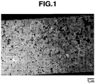
- FIG. 1 is a TEM image in section of a particle.
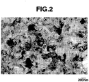
- FIG. 2 is an enlarged TEM image of crystal grains.
- FIG. 3 is a TEM image in section of a particle.
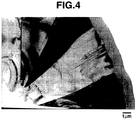
- FIG. 4 is a TEM image in section of a particle.
- the polycrystalline silicon particles thus obtained were measured for crystallite size, true specific gravity and particle size, with the results shown in Table 1. Note that the true specific gravity of polycrystalline silicon was determined by a gas adsorption method (pycnometer) using helium gas. Table 1 Crystallite size, nm True specific gravity D 50 , ⁇ m p-Si particle 1-1 24 2.308 0.5 p-Si particle I-2 25 2.309 6.1 p-Si particle I-3 25 2.308 11.0 p-Si particle I-4 25 2.308 15.7 p-Si particle I-5 30 2.320 9.5 p-Si particle I-6 35 2.326 9.1 Si particle I-1 43 2.335 9.2
- the electrolytic solution was a non-aqueous electrolyte solution of lithium bis(trifluoromethanesulfonyl)imide in a 1/1 (by volume) mixture of ethylene carbonate and diethyl carbonate in a concentration of 1 mol/liter.
- the separator was a porous polyethylene film of 30 ⁇ m thick.
- test cells were aged overnight at room temperature. Two of the test cells were disassembled immediately after aging, and thickness measurement was performed, that is, the thickness in the state swollen with electrolytic solution was measured. Note that an increment of lithium resulting from the electrolytic solution and charging was neglected. Next two of the test cells were tested by means of a secondary cell charge/discharge tester (Nagano K.K.). Charging was conducted with a constant current flow of 0.05 c until the voltage of the test cell reached 5 mV, and after reaching 5 mV, continued with a reduced current flow so that the cell voltage was kept at 5 mV, and terminated when the current flow decreased below 0.02 c.
- a secondary cell charge/discharge tester Nagano K.K.
- the test cells were disassembled, and thickness measurement was performed. A percent volume expansion upon charging was calculated.
- the same charging test was carried out, after which the cell was discharged with a constant current flow of 0.05 c until the cell voltage reached 1,500 mV.
- a charge/discharge capacity was determined, from which a 1st cycle charge/discharge efficiency was computed.
- the charge/discharge capacity is a capacity per active material excluding the binder.
- the 1st cycle charge/discharge efficiency is a percentage of discharge capacity relative to charge capacity.
- the positive electrode was a single layer sheet using LiCoO 2 as the active material and an aluminum foil as the current collector (trade name Pioxcel C-100 by Pionics Co., Ltd.).
- the non-aqueous electrolyte was a non-aqueous electrolyte solution of lithium hexafluorophosphate in a 1/1 (by volume) mixture of ethylene carbonate and diethyl carbonate in a concentration of 1 mol/liter.
- the separator was a porous polyethylene film of 30 ⁇ m thick.
- the cell was aged two nights at room temperature before it was tested by means of a secondary cell charge/discharge tester (Nagano K.K.). Charging was conducted with a constant current flow of 1.2 mA (0.25 c vs. positive electrode) until the voltage of the test cell reached 4.2 V, and after reaching 4.2 V, continued with a reduced current flow so that the cell voltage was kept at 4.2 V, and terminated when the current flow decreased below 0.3 mA. Discharging was conducted with a constant current flow of 0.6 mA and terminated when the cell voltage reached 2.5 V. A discharge capacity was determined. The charging/discharging operation was repeated 50 cycles.
- the precipitate was recovered and crushed by a jaw crusher.
- a lateral heating furnace was charged with the silicon oxide particles obtained above, evacuated by an oil rotary vacuum pump, and fed with CH 4 gas at 0.5 NL/min. Treatment under conditions of 1,000°C and 2,000 Pa continued for 5 hours whereby the particles were coated with graphite. At the end of operation, the furnace was cooled, and black particles were recovered.
- the black particles were conductive particles having an average particle size of 8.2 ⁇ m and a carbon buildup of 5% (based on the black particles).
- Black particles were prepared by the same procedure as above (II-1), without operating the oil rotary vacuum pump. That is, the silicon oxide particles were treated under atmospheric pressure at 1,150°C while feeding a mixture of Ar and CH 4 at 2.0 and 0.5 NL/min whereby the particles were coated with graphite.
- the black particles thus recovered were conductive particles having an average particle size of 8.5 ⁇ m and a carbon buildup of 5% (based on the black particles).
- Black particles were prepared by the same procedure as above (II-1) except that a vacuum of 30 Pa was established by operating not only the oil rotary vacuum pump, but also a mechanical booster pump.
- the silicon oxide particles were coated with graphite.
- the black particles thus recovered were conductive particles having an average particle size of 8.5 ⁇ m and a carbon buildup of 4.5% (based on the black particles).
- a lateral heating furnace was charged with the silicon particles II-2, where hot CVD was performed in a stream of methane gas at 1,100°C and 1,000 Pa for an average residence time of about 2 hours. At the end of operation, the furnace was cooled, and black particles were recovered.
- the black particles were conductive particles having an average particle size of 6.3 ⁇ m and a carbon buildup of 2% (based on the black particles).
- a polyimide resin (solids 18.1%) as a binder was added thereto to form a slurry.
- the slurry was coated onto a copper foil of 12 ⁇ m thick by means of a doctor blade having a gap of 50 ⁇ m, vacuum dried at 200°C for 2 hours, and pressed by a roller press at 60°C into a negative electrode shaped form. Finally, pieces of 2 cm 2 were punched out of the shaped form and used as a negative electrode.
- the composition of solid components is shown in Table 4.
- the charge/discharge capacity and volume expansion of the material were measured as follows.
- Six lithium ion secondary cells were fabricated using the shaped form as the negative electrode and a lithium foil as the counter electrode.
- the electrolytic solution was a non-aqueous electrolyte solution of lithium bis(trifluoromethanesulfonyl)imide in a 1/1 (by volume) mixture of ethylene carbonate and diethyl carbonate in a concentration of 1 mol/liter.
- the separator was a porous polyethylene film of 30 ⁇ m thick.
- test cells were aged overnight at room temperature. Two of the test cells were disassembled immediately after aging, and thickness measurement was performed, that is, the thickness in the state swollen with electrolytic solution was measured, from which a volume V1 prior to charging was determined. Note that an increment of lithium resulting from the electrolytic solution and charging was neglected.
- Next two of the test cells were tested by means of a secondary cell charge/discharge tester (Nagano K.K.). Charging was conducted with a constant current flow of 0.05 c until the voltage of the test cell reached 5 mV, and after reaching 5 mV, continued with a reduced current flow so that the cell voltage was kept at 5 mV, and terminated when the current flow decreased below 0.02 c.
- Example 1 A comparison of Example 1 with Reference Example 9 reveals that the negative electrode material within the scope of the invention has a lower factor of volumetric change after charging, despite equivalent capacity and discharge efficiency.
- the negative electrode materials of Examples 1 to 5 are improved in 1st cycle charge/discharge efficiency, with an increased charge/discharge capacity being observed.
- the factor of volumetric change remained substantially unchanged despite the increased charge/discharge capacity.
- the negative electrode shaped forms were prepared by the same procedure as described above.
- a coin-type lithium ion secondary cell was fabricated.
- the positive electrode was a single layer sheet using LiCoO 2 as the active material and an aluminum foil as the current collector (trade name Pioxcel C-100 by Pionics Co., Ltd.).
- the non-aqueous electrolyte was a non-aqueous electrolyte solution of lithium hexafluorophosphate in a 1/1 (by volume) mixture of ethylene carbonate and diethyl carbonate in a concentration of 1 mol/liter.
- the separator was a porous polyethylene film of 30 ⁇ m thick.
- the cell was aged two nights at room temperature before it was tested by means of a secondary cell charge/discharge tester (Nagano K.K.). Charging was conducted with a constant current flow of 1.2 mA (0.25 c vs. positive electrode) until the voltage of the test cell reached 4.2 V, and after reaching 4.2 V, continued with a reduced current flow so that the cell voltage was kept at 4.2 V, and terminated when the current flow decreased below 0.3 mA. Discharging was conducted with a constant current flow of 0.6 mA and terminated when the cell voltage reached 2.5 V. A discharge capacity was determined. The charging/discharging operation was repeated 50 cycles.
- Example 1 displayed substantially equivalent cycle performance to that prior to addition of silicon particles, despite increases of initial efficiency and battery capacity as compared with Comparative Example 3. Table 5 Discharge capacity retentivity after 50 cycles, % Example 1 84.5 Reference Example 9 82.2 Comparative Example 3 83.8
Landscapes
- Chemical & Material Sciences (AREA)
- Chemical Kinetics & Catalysis (AREA)
- Electrochemistry (AREA)
- General Chemical & Material Sciences (AREA)
- Engineering & Computer Science (AREA)
- Manufacturing & Machinery (AREA)
- Composite Materials (AREA)
- Materials Engineering (AREA)
- Inorganic Chemistry (AREA)
- Battery Electrode And Active Subsutance (AREA)
- Secondary Cells (AREA)
Claims (15)
- Negatives Elektrodenmaterial für nichtwässrige Elektrolyt-Sekundärbatterien, umfassend ein aktives Material und 1 bis 20 Gew.-% eines Bindemittels, wobei das aktive Material Folgendes umfasst:Siliciumoxidteilchen, die mittels chemischer Dampfabscheidung mit Kohlenstoff beschichtet wurden, undSiliciumteilchen, wobei die Siliciumteilchen in einer Menge von nicht mehr als 50 Gew.-%, bezogen auf das aktive Material, vorhanden sind;wobei das negative Elektrodenmaterial über ein Verfahren erhalten wird, das das Vereinigen der beschichteten Siliciumoxidteilchen mit den Siliciumteilchen und dem Bindemittel umfasst,und wobeider Kohlenstoff, mit dem die Siliciumoxidteilchen beschichtet sind, eine Graphitbeschichtung ist, die in einer Raman-Spektroskopie streuende Peaks mit Intensitäten I1330 und I1580 bei 1330 cm-1 und 1580 cm-1 aufweist, wobei das Intensitätsverhältnis von I1330 zu I1580 im Bereich 1,5 < I1330/I1580 < 3,0 liegt, unddie beschichteten Siliciumoxidteilchen in einer Feststoff-NMR-(29Si-DDMAS)-Analyse ein Signalfeld S-84 um -84 ppm und ein breites Signalfeld S-110 aufweisen, das sich um 110 ppm zentriert, wobei das Feldverhältnis S-84/S-110 0,5 < S-84/S-110 < 1,1 erfüllt.
- Negatives Elektrodenmaterial nach Anspruch 1, wobei das Siliciumoxid amorphes Siliciumoxid ist, das durch die Formel SiOx dargestellt wird, worin x im Bereich 1,0 ≤ x < 1,6 liegt.
- Negatives Elektrodenmaterial nach Anspruch 1 oder 2, wobei das Beschichtungsgewicht des Kohlenstoffs auf den Siliciumoxidteilchen 5 bis 20 Gew.-%, bezogen auf die mit Kohlenstoff beschichteten Siliciumoxidteilchen, beträgt.
- Negatives Elektrodenmaterial nach Anspruch 1, 2 oder 3, wobei die Siliciumteilchen polykristalline Siliciumteilchen sind.
- Negatives Elektrodenmaterial nach Anspruch 4, wobei die polykristallinen Siliciumteilchen eine Kristallgröße von 20 nm bis 34 nm aufweisen, wie mittels Röntgenbeugungsanalyse über die Scherer-Gleichung aus der FWHM (volle Breite bei halbem Maximum) einer Beugungskurve bestimmt, die Si(111) um 2θ = 28,4° zugewiesen wurde.
- Negatives Elektrodenmaterial nach Anspruch 4 oder 5, wobei die polykristallinen Siliciumteilchen ein wahres spezifisches Gewicht von 2,300 bis 2,320 aufweisen.
- Negatives Elektrodenmaterial nach einem der Ansprüche 4 bis 6, wobei die polykristallinen Siliciumteilchen einen mittleren Durchmesser D50 von 0,1 bis 20 µm aufweisen.
- Negatives Elektrodenmaterial nach einem der vorangegangenen Ansprüche, wobei die Siliciumoxidteilchen einen mittleren Durchmesser D50 von 1 bis 20 µm aufweisen.
- Negatives Elektrodenmaterial nach einem der vorangegangenen Ansprüche, wobei die Siliciumteilchen Siliciumteilchen sind, deren Oberfläche mit einer Graphitbeschichtung beschichtet wurde.
- Negatives Elektrodenmaterial nach einem der vorangegangenen Ansprüche, wobei das Bindemittel ein Polyimidharz umfasst.
- Negative Elektrode für nichtwässrige Elektrolyt-Sekundärbatterien, umfassend ein negatives Elektrodenmaterial nach einem der Ansprüche 1 bis 10.
- Nichtwässrige Elektrolyt-Sekundärbatterie, umfassend eine negative Elektrode nach Anspruch 11, eine positive Elektrode, einen Separator und einen nichtwässrigen Elektrolyten.
- Nichtwässrige Elektrolyt-Sekundärbatterie nach Anspruch 12, die eine Lithiumionen-Sekundärbatterie ist.
- Verfahren zur Herstellung eines negativen Elektrodenmaterials nach einem der Ansprüche 1 bis 10, umfassend die folgenden Schritte:(I) Durchführen einer chemischen Dampfabscheidung eines organischen Gases und/oder Dampfs auf Siliciumoxidteilchen unter Vakuum bei 50 bis 30.000 Pa bei 600 bis 1100 °C, um Oberflächen der Siliciumoxidteilchen mit der Graphitbeschichtung zu beschichten, und(II) Vereinigen der aus Schritt (I) resultierenden beschichteten Siliciumoxidteilchen mit den Siliciumteilchen und dem Bindemittel.
- Verfahren nach Anspruch 14, wobei die Silicumoxidteilchen und die beschichteten Siliciumoxidteilchen in allen Schritten unter einer Atmosphäre von bis zu 1100 °C gehalten werden.
Applications Claiming Priority (2)
| Application Number | Priority Date | Filing Date | Title |
|---|---|---|---|
| JP2008067073A JP4844764B2 (ja) | 2008-03-17 | 2008-03-17 | 非水電解質二次電池負極及びそれを用いた非水電解質二次電池 |
| JP2008109769A JP5272492B2 (ja) | 2008-04-21 | 2008-04-21 | 非水電解質二次電池用負極材及びその製造方法、ならびに非水電解質二次電池用負極及び非水電解質二次電池 |
Publications (3)
| Publication Number | Publication Date |
|---|---|
| EP2104175A2 EP2104175A2 (de) | 2009-09-23 |
| EP2104175A3 EP2104175A3 (de) | 2010-12-01 |
| EP2104175B1 true EP2104175B1 (de) | 2019-05-22 |
Family
ID=40836412
Family Applications (1)
| Application Number | Title | Priority Date | Filing Date |
|---|---|---|---|
| EP09250738.3A Active EP2104175B1 (de) | 2008-03-17 | 2009-03-17 | Nichtwässrige Elektrolyt-Sekundärbatterie, negatives Elektrodenmaterial und Herstellungsverfahren |
Country Status (3)
| Country | Link |
|---|---|
| US (1) | US8105718B2 (de) |
| EP (1) | EP2104175B1 (de) |
| KR (1) | KR101406013B1 (de) |
Cited By (1)
| Publication number | Priority date | Publication date | Assignee | Title |
|---|---|---|---|---|
| EP4462505A4 (de) * | 2022-07-13 | 2025-07-02 | Lg Energy Solution Ltd | Anodenaktivmaterial, verfahren zur herstellung eines anodenaktivmaterials, anodenzusammensetzung, anode für lithiumsekundärbatterie damit und lithiumsekundärbatterie mit anode |
Families Citing this family (109)
| Publication number | Priority date | Publication date | Assignee | Title |
|---|---|---|---|---|
| GB2395059B (en) | 2002-11-05 | 2005-03-16 | Imp College Innovations Ltd | Structured silicon anode |
| JP4401984B2 (ja) | 2004-03-08 | 2010-01-20 | 三星エスディアイ株式会社 | リチウム二次電池用負極活物質、リチウム二次電池用負極活物質、およびリチウム二次電池 |
| GB0601319D0 (en) | 2006-01-23 | 2006-03-01 | Imp Innovations Ltd | A method of fabricating pillars composed of silicon-based material |
| GB0601318D0 (en) * | 2006-01-23 | 2006-03-01 | Imp Innovations Ltd | Method of etching a silicon-based material |
| KR101328982B1 (ko) * | 2006-04-17 | 2013-11-13 | 삼성에스디아이 주식회사 | 음극 활물질 및 그 제조 방법 |
| KR100818263B1 (ko) * | 2006-12-19 | 2008-03-31 | 삼성에스디아이 주식회사 | 다공성 음극 활물질, 그 제조 방법 및 이를 채용한 음극과리튬 전지 |
| GB0709165D0 (en) * | 2007-05-11 | 2007-06-20 | Nexeon Ltd | A silicon anode for a rechargeable battery |
| GB0713898D0 (en) | 2007-07-17 | 2007-08-29 | Nexeon Ltd | A method of fabricating structured particles composed of silcon or a silicon-based material and their use in lithium rechargeable batteries |
| GB0713896D0 (en) | 2007-07-17 | 2007-08-29 | Nexeon Ltd | Method |
| GB0713895D0 (en) | 2007-07-17 | 2007-08-29 | Nexeon Ltd | Production |
| GB2464157B (en) | 2008-10-10 | 2010-09-01 | Nexeon Ltd | A method of fabricating structured particles composed of silicon or a silicon-based material |
| GB2464158B (en) | 2008-10-10 | 2011-04-20 | Nexeon Ltd | A method of fabricating structured particles composed of silicon or a silicon-based material and their use in lithium rechargeable batteries |
| GB2470056B (en) | 2009-05-07 | 2013-09-11 | Nexeon Ltd | A method of making silicon anode material for rechargeable cells |
| GB2495951B (en) | 2011-10-26 | 2014-07-16 | Nexeon Ltd | A composition for a secondary battery cell |
| GB2470190B (en) | 2009-05-11 | 2011-07-13 | Nexeon Ltd | A binder for lithium ion rechargeable battery cells |
| US9853292B2 (en) | 2009-05-11 | 2017-12-26 | Nexeon Limited | Electrode composition for a secondary battery cell |
| EP3439082A1 (de) | 2009-09-29 | 2019-02-06 | Georgia Tech Research Corporation | Elektroden und lithiumionenbatterien |
| TW201133983A (en) * | 2009-11-03 | 2011-10-01 | Envia Systems Inc | High capacity anode materials for lithium ion batteries |
| JP5659696B2 (ja) * | 2009-12-24 | 2015-01-28 | ソニー株式会社 | リチウムイオン二次電池、リチウムイオン二次電池用負極、電動工具、電気自動車および電力貯蔵システム |
| US9178208B2 (en) | 2010-01-18 | 2015-11-03 | Evevate Corporation | Composite materials for electrochemical storage |
| US20170040598A1 (en) | 2015-08-07 | 2017-02-09 | Enevate Corporation | Surface modification of silicon particles for electrochemical storage |
| US11380890B2 (en) | 2010-01-18 | 2022-07-05 | Enevate Corporation | Surface modification of silicon particles for electrochemical storage |
| US10461366B1 (en) | 2010-01-18 | 2019-10-29 | Enevate Corporation | Electrolyte compositions for batteries |
| US9553303B2 (en) | 2010-01-18 | 2017-01-24 | Enevate Corporation | Silicon particles for battery electrodes |
| US9077029B2 (en) * | 2010-02-23 | 2015-07-07 | Samsung Sdi Co., Ltd. | Negative active material for rechargeable lithium battery and rechargeable lithium battery including the same |
| GB201005979D0 (en) | 2010-04-09 | 2010-05-26 | Nexeon Ltd | A method of fabricating structured particles composed of silicon or a silicon-based material and their use in lithium rechargeable batteries |
| JP5666378B2 (ja) | 2010-05-24 | 2015-02-12 | 信越化学工業株式会社 | 非水電解質二次電池用負極活物質の製造方法及び非水電解質二次電池用負極活物質並びに非水電解質二次電池用負極材、非水電解質二次電池用負極、非水電解質二次電池 |
| GB201009519D0 (en) | 2010-06-07 | 2010-07-21 | Nexeon Ltd | An additive for lithium ion rechargeable battery cells |
| US8956762B2 (en) | 2010-07-29 | 2015-02-17 | Nec Corporation | Lithium ion secondary battery and method for manufacturing the same |
| WO2012029388A1 (ja) * | 2010-09-02 | 2012-03-08 | 日本電気株式会社 | 二次電池 |
| GB201014706D0 (en) | 2010-09-03 | 2010-10-20 | Nexeon Ltd | Porous electroactive material |
| GB201014707D0 (en) * | 2010-09-03 | 2010-10-20 | Nexeon Ltd | Electroactive material |
| WO2012036127A1 (ja) | 2010-09-14 | 2012-03-22 | 日立マクセルエナジー株式会社 | 非水二次電池 |
| US10290894B2 (en) * | 2010-10-29 | 2019-05-14 | Nec Corporation | Secondary battery and method for manufacturing same |
| KR101126202B1 (ko) | 2010-11-04 | 2012-03-22 | 삼성에스디아이 주식회사 | 리튬 이차 전지용 음극 활물질 및 이를 포함하는 리튬 이차 전지 |
| JP6010279B2 (ja) * | 2011-04-08 | 2016-10-19 | 信越化学工業株式会社 | 非水電解質二次電池用負極活物質の製造方法 |
| US9601228B2 (en) | 2011-05-16 | 2017-03-21 | Envia Systems, Inc. | Silicon oxide based high capacity anode materials for lithium ion batteries |
| JPWO2012161055A1 (ja) * | 2011-05-23 | 2014-07-31 | 国立大学法人 名古屋工業大学 | エネルギーデバイス及び蓄電デバイスの内の少なくともいずれか一方に用いられる材料の製造方法 |
| GB2492167C (en) | 2011-06-24 | 2018-12-05 | Nexeon Ltd | Structured particles |
| TWI453298B (zh) * | 2011-08-01 | 2014-09-21 | Chien Te Hsieh | 粉體改質之氣相沈積方法、電極製作方法及其電極 |
| KR20130024769A (ko) | 2011-08-30 | 2013-03-08 | 가부시키가이샤 한도오따이 에네루기 켄큐쇼 | 축전 장치 |
| US11502326B2 (en) | 2011-09-21 | 2022-11-15 | Samsung Sdi Co., Ltd. | Negative active material for rechargeable lithium battery, method of preparing the same and rechargeable lithium battery including the same |
| US9139441B2 (en) | 2012-01-19 | 2015-09-22 | Envia Systems, Inc. | Porous silicon based anode material formed using metal reduction |
| US9409777B2 (en) | 2012-02-09 | 2016-08-09 | Basf Se | Preparation of polymeric resins and carbon materials |
| CN104170153A (zh) * | 2012-03-02 | 2014-11-26 | 日本电气株式会社 | 二次电池 |
| US9090476B2 (en) * | 2012-03-22 | 2015-07-28 | Chun-Chieh Chang | Direct deposition of graphene on substrate material |
| JP5621867B2 (ja) | 2012-03-27 | 2014-11-12 | Tdk株式会社 | リチウムイオン二次電池 |
| JP5621868B2 (ja) * | 2012-03-27 | 2014-11-12 | Tdk株式会社 | リチウムイオン二次電池 |
| EP2690689A1 (de) * | 2012-07-25 | 2014-01-29 | Umicore | Kostengünstige Si-basierte Negativelektroden mit verbesserter Zyklisierungsleistung |
| US9780358B2 (en) | 2012-05-04 | 2017-10-03 | Zenlabs Energy, Inc. | Battery designs with high capacity anode materials and cathode materials |
| US10553871B2 (en) | 2012-05-04 | 2020-02-04 | Zenlabs Energy, Inc. | Battery cell engineering and design to reach high energy |
| US9362552B2 (en) * | 2012-06-01 | 2016-06-07 | GM Global Technology Operations LLC | Lithium ion battery electrode materials and methods of making the same |
| KR20140022682A (ko) | 2012-08-14 | 2014-02-25 | 삼성에스디아이 주식회사 | 리튬 이차 전지용 음극 활물질, 및 이를 포함하는 음극 및 리튬 이차 전지 |
| JP5900244B2 (ja) * | 2012-08-23 | 2016-04-06 | トヨタ自動車株式会社 | 固体電池の製造方法 |
| KR101560454B1 (ko) | 2012-10-16 | 2015-10-15 | 주식회사 엘지화학 | 규소 산화물―탄소 복합체 및 이의 제조방법 |
| JP6010429B2 (ja) * | 2012-11-08 | 2016-10-19 | 信越化学工業株式会社 | 非水電解質二次電池用負極活物質用の珪素含有粒子の製造方法、非水電解質二次電池用負極材の製造方法、及び非水電解質二次電池の製造方法 |
| EP2922120A4 (de) | 2012-11-13 | 2016-11-30 | Nec Corp | Negativelektrodenaktivsubstanz, verfahren zur herstellung davon und lithiumsekundärzelle |
| JP6241911B2 (ja) | 2012-11-13 | 2017-12-06 | 日東電工株式会社 | 活物質粒子、蓄電デバイス用正極、蓄電デバイスおよび活物質粒子の製造方法 |
| EP2924778B1 (de) * | 2012-11-22 | 2018-09-19 | Nissan Motor Co., Ltd | Negativelektrode für eine elektrische vorrichtung und damit ausgestattete elektrische vorrichtung |
| IN2014MN02637A (de) * | 2012-12-06 | 2015-10-16 | Lg Chemical Ltd | |
| JP6006662B2 (ja) | 2013-03-05 | 2016-10-12 | 信越化学工業株式会社 | 珪素含有粒子の製造方法、非水電解質二次電池の負極材の製造方法、および、非水電解質二次電池の製造方法 |
| US11450850B2 (en) * | 2019-11-12 | 2022-09-20 | Enevate Corporation | Configuring anisotropic expansion of silicon-dominant anodes using particle size |
| JP5827261B2 (ja) * | 2013-03-28 | 2015-12-02 | 信越化学工業株式会社 | 珪素含有粒子、非水電解質二次電池の負極材、および、非水電解質二次電池 |
| US10020491B2 (en) | 2013-04-16 | 2018-07-10 | Zenlabs Energy, Inc. | Silicon-based active materials for lithium ion batteries and synthesis with solution processing |
| JP6030995B2 (ja) * | 2013-05-15 | 2016-11-24 | 信越化学工業株式会社 | 非水電解質二次電池用負極材及びその製造方法並びにリチウムイオン二次電池 |
| CN104218275B (zh) * | 2013-05-31 | 2018-03-27 | 华为技术有限公司 | 一种锂空气电池及其制备方法 |
| US10886526B2 (en) | 2013-06-13 | 2021-01-05 | Zenlabs Energy, Inc. | Silicon-silicon oxide-carbon composites for lithium battery electrodes and methods for forming the composites |
| CN104241597A (zh) * | 2013-06-14 | 2014-12-24 | 上海绿孚新能源科技有限公司 | 二次电池及用于二次电池的电极 |
| WO2015003725A1 (en) | 2013-07-09 | 2015-01-15 | Friedrich-Schiller-Universität Jena | Electroactive polymers, manufacturing process thereof, electrode and use thereof |
| CN105453314B (zh) | 2013-08-05 | 2017-10-20 | 昭和电工株式会社 | 锂离子电池用负极材料和其用途 |
| US11476494B2 (en) | 2013-08-16 | 2022-10-18 | Zenlabs Energy, Inc. | Lithium ion batteries with high capacity anode active material and good cycling for consumer electronics |
| US9935309B2 (en) | 2013-08-21 | 2018-04-03 | Shin-Etsu Chemical Co., Ltd. | Negative electrode active material, raw material for a negative electrode active material, negative electrode, lithium ion secondary battery, method for producing a negative electrode active material, and method for producing a lithium ion secondary battery |
| EP3014680B1 (de) * | 2013-10-15 | 2017-04-12 | Nexeon Limited | Verstärktes stromableiter-substratelemente für elektrochemische zellen |
| KR102176590B1 (ko) * | 2013-12-30 | 2020-11-09 | 삼성전자주식회사 | 리튬 이차전지용 음극 활물질의 제조방법 및 리튬 이차전지 |
| JP6202106B2 (ja) | 2014-01-24 | 2017-09-27 | 日産自動車株式会社 | 電気デバイス |
| JP6187602B2 (ja) | 2014-01-24 | 2017-08-30 | 日産自動車株式会社 | 電気デバイス |
| CN105960724B (zh) | 2014-02-04 | 2019-02-15 | 三井化学株式会社 | 锂离子二次电池用负极及其制造方法 |
| JP6281306B2 (ja) * | 2014-02-06 | 2018-02-21 | 信越化学工業株式会社 | リチウムイオン二次電池用負極材、その製造方法、負極及びリチウムイオン二次電池 |
| JP6665121B2 (ja) | 2014-03-14 | 2020-03-13 | グループ14・テクノロジーズ・インコーポレイテッドGroup14 Technologies, Inc. | 無溶媒中におけるゾル−ゲル重合のための新規方法、及びゾル−ゲル重合由来の可変炭素構造の作製 |
| KR101567203B1 (ko) | 2014-04-09 | 2015-11-09 | (주)오렌지파워 | 이차 전지용 음극 활물질 및 이의 방법 |
| KR101604352B1 (ko) | 2014-04-22 | 2016-03-18 | (주)오렌지파워 | 음극 활물질 및 이를 포함하는 리튬 이차 전지 |
| DE102014207881A1 (de) * | 2014-04-25 | 2015-10-29 | Volkswagen Aktiengesellschaft | Herstellverfahren von nanoskaligen Siliziumpartikeln mit einer reduzierten Siliziumdioxid-Beschichtung |
| DE102014210086A1 (de) | 2014-05-27 | 2015-12-03 | Robert Bosch Gmbh | Siliciumpartikel mit mikroorganismusförmigem Hohlraum |
| CN104198970B (zh) * | 2014-09-05 | 2017-01-18 | 厦门大学 | 一种在不均匀磁场下获取高分辨核磁共振谱图的方法 |
| GB2533161C (en) | 2014-12-12 | 2019-07-24 | Nexeon Ltd | Electrodes for metal-ion batteries |
| WO2016137024A1 (ko) | 2015-02-24 | 2016-09-01 | (주)오렌지파워 | 실리콘 음극 활물질 및 이의 제조 방법 |
| US10446837B2 (en) * | 2015-02-26 | 2019-10-15 | Shin-Etsu Chemical Co., Ltd. | Negative electrode active material for non-aqueous electrolyte secondary battery, negative electrode for non-aqueous electrolyte secondary battery, non-aqueous electrolyte secondary battery, and method of producing negative electrode material for a non-aqueous electrolyte secondary battery |
| WO2017031006A1 (en) | 2015-08-14 | 2017-02-23 | Energ2 Technologies, Inc. | Composites of porous nano-featured silicon materials and carbon materials |
| WO2017150311A1 (ja) * | 2016-02-29 | 2017-09-08 | 日本電気株式会社 | 負極活物質およびそれを用いたリチウムイオン二次電池 |
| JP6567448B2 (ja) | 2016-03-16 | 2019-08-28 | 株式会社東芝 | 非水電解質電池用電極材料、非水電解質電池用電極、それを備えた非水電解質電池および電池パック、車両 |
| JP6921481B2 (ja) | 2016-03-17 | 2021-08-18 | 株式会社東芝 | 非水電解質電池用電極材料、非水電解質電池用電極、それを備えた非水電解質電池および電池パック、車両 |
| JP6470223B2 (ja) * | 2016-04-04 | 2019-02-13 | 信越化学工業株式会社 | 単結晶シリコンの製造方法 |
| WO2018081224A1 (en) | 2016-10-26 | 2018-05-03 | The Regents Of The University Of Michigan | Metal infiltrated electrodes for solid state batteries |
| GB201803983D0 (en) | 2017-09-13 | 2018-04-25 | Unifrax I Llc | Materials |
| KR102236365B1 (ko) * | 2017-12-05 | 2021-04-06 | 대주전자재료 주식회사 | 비수전해질 이차전지용 음극활물질 및 이의 제조 방법 |
| KR102855942B1 (ko) | 2017-12-07 | 2025-09-04 | 에네베이트 코포레이션 | 탄화규소 및 탄소 입자를 포함하는 복합물 |
| US12548760B2 (en) | 2017-12-07 | 2026-02-10 | Enevate Corporation | Silicon particles for battery electrodes |
| US11094925B2 (en) | 2017-12-22 | 2021-08-17 | Zenlabs Energy, Inc. | Electrodes with silicon oxide active materials for lithium ion cells achieving high capacity, high energy density and long cycle life performance |
| US10974965B2 (en) | 2018-01-26 | 2021-04-13 | Samsung Electronics Co., Ltd. | Silicon-containing structure, method of preparing the same, carbon composite using the same, and electrode, lithium battery, and device each including the same |
| JP7050581B2 (ja) * | 2018-06-04 | 2022-04-08 | 信越化学工業株式会社 | 多結晶シリコンロッドの選別方法 |
| CN109324030A (zh) * | 2018-09-21 | 2019-02-12 | 合肥国轩高科动力能源有限公司 | 一种锂离子电池负极用氧化亚硅-无定形碳复合材料的表征方法 |
| US20220052323A1 (en) * | 2019-02-27 | 2022-02-17 | The Regents Of The University Of California | Synthesis of graphitic shells on silicon nanoparticles |
| US11973178B2 (en) | 2019-06-26 | 2024-04-30 | Ionblox, Inc. | Lithium ion cells with high performance electrolyte and silicon oxide active materials achieving very long cycle life performance |
| CN110729472A (zh) * | 2019-10-28 | 2020-01-24 | 中科廊坊过程工程研究院 | 一种硅基负极材料、其制备方法和用途 |
| US12355079B2 (en) | 2020-07-02 | 2025-07-08 | Ionblox, Inc. | Lithium ion cells with silicon based active materials and negative electrodes with water-based binders having good adhesion and cohesion |
| US11335903B2 (en) | 2020-08-18 | 2022-05-17 | Group14 Technologies, Inc. | Highly efficient manufacturing of silicon-carbon composites materials comprising ultra low z |
| CN112687853B (zh) * | 2020-12-10 | 2022-08-16 | 安普瑞斯(南京)有限公司 | 硅氧颗粒团聚体及其制备方法、负极材料、电池 |
| US11387443B1 (en) | 2021-11-22 | 2022-07-12 | Enevate Corporation | Silicon based lithium ion battery and improved cycle life of same |
| CN115020684B (zh) * | 2022-07-26 | 2023-10-20 | 蜂巢能源科技股份有限公司 | 一种石墨、硅氧化物和硅复合的负极材料及其应用 |
Citations (1)
| Publication number | Priority date | Publication date | Assignee | Title |
|---|---|---|---|---|
| JP2004139886A (ja) * | 2002-10-18 | 2004-05-13 | Japan Storage Battery Co Ltd | 非水電解質二次電池 |
Family Cites Families (51)
| Publication number | Priority date | Publication date | Assignee | Title |
|---|---|---|---|---|
| JPS6092260A (ja) | 1983-10-27 | 1985-05-23 | Nippon Tokushu Noyaku Seizo Kk | 新規アニリン誘導体 |
| JP2964732B2 (ja) | 1991-09-09 | 1999-10-18 | 株式会社ユアサコーポレーション | 二次電池 |
| JP3008228B2 (ja) | 1991-12-18 | 2000-02-14 | セイコーインスツルメンツ株式会社 | 非水電解質二次電池及びその負極活物質の製造方法 |
| JP3242751B2 (ja) | 1992-04-24 | 2001-12-25 | 富士写真フイルム株式会社 | 非水二次電池 |
| US5478671A (en) * | 1992-04-24 | 1995-12-26 | Fuji Photo Film Co., Ltd. | Nonaqueous secondary battery |
| JP2997741B2 (ja) | 1992-07-29 | 2000-01-11 | セイコーインスツルメンツ株式会社 | 非水電解質二次電池及びその製造方法 |
| JPH0692617A (ja) * | 1992-09-07 | 1994-04-05 | Toagosei Chem Ind Co Ltd | 種シリコン粒子の製造方法及び顆粒状多結晶シリコンの製造方法 |
| US5401599A (en) * | 1992-10-02 | 1995-03-28 | Seiko Instruments Inc. | Non-aqueous electrolyte secondary battery and method of producing the same |
| JPH06127920A (ja) * | 1992-10-15 | 1994-05-10 | Tonen Chem Corp | 多結晶シリコン粒子棒状成形体及びその製造方法 |
| JPH06191818A (ja) | 1992-12-22 | 1994-07-12 | Tonen Chem Corp | 多結晶シリコンの製造方法 |
| JP3079343B2 (ja) | 1993-07-13 | 2000-08-21 | セイコーインスツルメンツ株式会社 | 非水電解質二次電池及びその製造方法 |
| JP3846661B2 (ja) | 1997-02-24 | 2006-11-15 | 日立マクセル株式会社 | リチウム二次電池 |
| JP3918311B2 (ja) | 1997-07-29 | 2007-05-23 | ソニー株式会社 | 負極材料及びこれを用いた非水電解液二次電池 |
| US6066414A (en) * | 1997-07-29 | 2000-05-23 | Sony Corporation | Material of negative electrode and nonaqueous-electrolyte secondary battery using the same |
| JPH1186847A (ja) | 1997-09-03 | 1999-03-30 | Japan Storage Battery Co Ltd | 非水電解質二次電池の製造方法 |
| KR100609862B1 (ko) * | 1998-12-03 | 2006-08-09 | 카오 코퍼레이션 | 리튬 2차 전지 및 그의 제조방법 |
| JP3291260B2 (ja) | 1998-12-03 | 2002-06-10 | 花王株式会社 | リチウム二次電池 |
| JP2000173596A (ja) | 1998-12-03 | 2000-06-23 | Kao Corp | 非水系二次電池 |
| JP4393610B2 (ja) * | 1999-01-26 | 2010-01-06 | 日本コークス工業株式会社 | リチウム二次電池用負極材料、リチウム二次電池、及び同二次電池の充電方法 |
| JP2000243396A (ja) * | 1999-02-23 | 2000-09-08 | Hitachi Ltd | リチウム二次電池とその製造方法及びその負極材並びに電気機器 |
| JP3865033B2 (ja) * | 2000-02-04 | 2007-01-10 | 信越化学工業株式会社 | 酸化珪素粉末の連続製造方法及び連続製造装置 |
| JP3622629B2 (ja) | 2000-04-06 | 2005-02-23 | 住友金属工業株式会社 | 非水電解質二次電池用負極材料の製造方法 |
| JP3622631B2 (ja) | 2000-04-14 | 2005-02-23 | 住友金属工業株式会社 | 非水電解質二次電池とその負極材料および該材料の製法 |
| JP2002042806A (ja) | 2000-07-19 | 2002-02-08 | Japan Storage Battery Co Ltd | 非水電解質二次電池 |
| JP2002075351A (ja) | 2000-09-04 | 2002-03-15 | Sumitomo Metal Ind Ltd | 非水電解質二次電池負極用合金粉末とその製造方法 |
| KR100411180B1 (ko) | 2001-01-03 | 2003-12-18 | 한국화학연구원 | 다결정실리콘의 제조방법과 그 장치 |
| JP2003109590A (ja) | 2001-09-28 | 2003-04-11 | Mitsubishi Materials Corp | 負極材料及びこれを用いた負極、並びにこの負極を用いた非水電解液リチウム二次電池及びリチウムイオンポリマー二次電池 |
| JP3982230B2 (ja) | 2001-10-18 | 2007-09-26 | 日本電気株式会社 | 二次電池用負極およびそれを用いた二次電池 |
| JP4225727B2 (ja) * | 2001-12-28 | 2009-02-18 | 三洋電機株式会社 | リチウム二次電池用負極及びリチウム二次電池 |
| JP4288455B2 (ja) | 2002-04-19 | 2009-07-01 | 信越化学工業株式会社 | 非水電解質二次電池負極材の製造方法 |
| US8092940B2 (en) * | 2002-05-08 | 2012-01-10 | Gs Yuasa International Ltd. | Non-aqueous electrolyte secondary battery |
| JP3952180B2 (ja) | 2002-05-17 | 2007-08-01 | 信越化学工業株式会社 | 導電性珪素複合体及びその製造方法並びに非水電解質二次電池用負極材 |
| TWI278429B (en) | 2002-05-17 | 2007-04-11 | Shinetsu Chemical Co | Conductive silicon composite, preparation thereof, and negative electrode material for non-aqueous electrolyte secondary cell |
| JP4025995B2 (ja) * | 2002-11-26 | 2007-12-26 | 信越化学工業株式会社 | 非水電解質二次電池負極材及びその製造方法並びにリチウムイオン二次電池 |
| JP2004185991A (ja) | 2002-12-03 | 2004-07-02 | Mitsubishi Materials Corp | リチウム二次電池用負極材料及びこれを用いたリチウム二次電池並びにこの負極材料の製造方法 |
| JP4007228B2 (ja) | 2003-03-31 | 2007-11-14 | 三菱マテリアル株式会社 | リチウム二次電池用負極材料及びその製造方法 |
| JP4368193B2 (ja) | 2003-12-26 | 2009-11-18 | 三洋電機株式会社 | リチウム前駆体電池及びリチウム二次電池の製造方法 |
| JP5011629B2 (ja) | 2004-02-19 | 2012-08-29 | 株式会社Gsユアサ | 非水電解質二次電池 |
| JP2005243431A (ja) | 2004-02-26 | 2005-09-08 | Japan Storage Battery Co Ltd | 非水電解質二次電池 |
| JP2005317309A (ja) | 2004-04-28 | 2005-11-10 | Sanyo Electric Co Ltd | リチウム二次電池 |
| JP2006216374A (ja) | 2005-02-03 | 2006-08-17 | Sony Corp | 負極材料およびそれを用いた電池 |
| JP2006236684A (ja) | 2005-02-23 | 2006-09-07 | Sony Corp | 負極,電池およびそれらの製造方法 |
| JP2006338996A (ja) | 2005-06-01 | 2006-12-14 | Sony Corp | 二次電池用負極、二次電池および二次電池用負極の製造方法 |
| JP2006339092A (ja) * | 2005-06-06 | 2006-12-14 | Matsushita Electric Ind Co Ltd | 非水電解液二次電池およびその負極 |
| JP4994631B2 (ja) * | 2005-10-12 | 2012-08-08 | パナソニック株式会社 | 非水電解質二次電池およびその正極活物質 |
| JP4876531B2 (ja) | 2005-10-27 | 2012-02-15 | パナソニック株式会社 | リチウム二次電池用負極およびリチウム二次電池の製造方法 |
| US7776473B2 (en) * | 2006-03-27 | 2010-08-17 | Shin-Etsu Chemical Co., Ltd. | Silicon-silicon oxide-lithium composite, making method, and non-aqueous electrolyte secondary cell negative electrode material |
| WO2007114168A1 (ja) | 2006-03-30 | 2007-10-11 | Sanyo Electric Co., Ltd. | リチウム二次電池及びその製造方法 |
| JP4207055B2 (ja) | 2006-04-26 | 2009-01-14 | 信越化学工業株式会社 | SiOx(x<1)の製造方法 |
| JP5398962B2 (ja) * | 2006-06-30 | 2014-01-29 | 三洋電機株式会社 | リチウム二次電池及びその製造方法 |
| TWI416780B (zh) * | 2006-08-30 | 2013-11-21 | Shinetsu Chemical Co | Non-aqueous battery separator, method for manufacturing the same, and nonaqueous electrolyte battery |
-
2009
- 2009-03-16 KR KR1020090022214A patent/KR101406013B1/ko active Active
- 2009-03-16 US US12/404,710 patent/US8105718B2/en active Active
- 2009-03-17 EP EP09250738.3A patent/EP2104175B1/de active Active
Patent Citations (1)
| Publication number | Priority date | Publication date | Assignee | Title |
|---|---|---|---|---|
| JP2004139886A (ja) * | 2002-10-18 | 2004-05-13 | Japan Storage Battery Co Ltd | 非水電解質二次電池 |
Cited By (1)
| Publication number | Priority date | Publication date | Assignee | Title |
|---|---|---|---|---|
| EP4462505A4 (de) * | 2022-07-13 | 2025-07-02 | Lg Energy Solution Ltd | Anodenaktivmaterial, verfahren zur herstellung eines anodenaktivmaterials, anodenzusammensetzung, anode für lithiumsekundärbatterie damit und lithiumsekundärbatterie mit anode |
Also Published As
| Publication number | Publication date |
|---|---|
| EP2104175A3 (de) | 2010-12-01 |
| US20090239151A1 (en) | 2009-09-24 |
| KR101406013B1 (ko) | 2014-06-11 |
| KR20090099487A (ko) | 2009-09-22 |
| EP2104175A2 (de) | 2009-09-23 |
| US8105718B2 (en) | 2012-01-31 |
Similar Documents
| Publication | Publication Date | Title |
|---|---|---|
| US8105718B2 (en) | Non-aqueous electrolyte secondary battery, negative electrode material, and making method | |
| EP2509139B1 (de) | Verfahren zur Herstellung von Negativ-Elektrodenaktivmaterial zur Verwendung in einer nichtwässrigen Elektrolyt-Sekundärbatterie, Negativ-Elektrodenmaterial zur Verwendung in einer nichtwässrigen Elektrolyt-Sekundärbatterie und nichtwässrige Elektrolyt-Sekundärbatterie | |
| US9142858B2 (en) | Non-aqueous electrolyte secondary battery, negative electrode, negative electrode material, and preparation of Si—O—Al composite | |
| US8734991B2 (en) | Negative electrode material for nonaqueous electrolyte secondary battery | |
| US9537142B2 (en) | Method for manufacturing negative electrode active material for non-aqueous electrolyte secondary battery | |
| JP4844764B2 (ja) | 非水電解質二次電池負極及びそれを用いた非水電解質二次電池 | |
| US20090317722A1 (en) | Negative electrode material, non-aqueous electrolyte secondary battery, and electrochemical capacitor | |
| JP5272492B2 (ja) | 非水電解質二次電池用負極材及びその製造方法、ならびに非水電解質二次電池用負極及び非水電解質二次電池 | |
| EP2590248B1 (de) | Aktivmaterial für negative Elektroden für Sekundärbatterie mit nichtwässrigem Elektrolyten und Herstellungsverfahren dafür | |
| US20110287313A1 (en) | Silicon oxide material for nonaqueous electrolyte secondary battery negative electrode material, making method, negative electrode, lithium ion secondary battery, and electrochemical capacitor | |
| EP2966712A1 (de) | Siliciumhaltige partikel, negativelektrodenmaterial für sekundärbatterien mit nichtwässrigem elektrolyten und sekundärbatterie mit nichtwässrigem elektrolyten | |
| EP2919301A1 (de) | Verfahren zur herstellung siliciumhaltiger teilchen für anodenaktivmaterial für sekundärbatterie mit wasserfreiem analyt, anodenelement für sekundärbatterie mit wasserfreiem elektrolyt, sekundärbatterie mit wasserfreiem elektrolyt und siliciumhaltige partikel für anodenaktivmaterial für sekundärbatterie mit wasserfreiem analyt |
Legal Events
| Date | Code | Title | Description |
|---|---|---|---|
| PUAI | Public reference made under article 153(3) epc to a published international application that has entered the european phase |
Free format text: ORIGINAL CODE: 0009012 |
|
| AK | Designated contracting states |
Kind code of ref document: A2 Designated state(s): AT BE BG CH CY CZ DE DK EE ES FI FR GB GR HR HU IE IS IT LI LT LU LV MC MK MT NL NO PL PT RO SE SI SK TR |
|
| AX | Request for extension of the european patent |
Extension state: AL BA RS |
|
| PUAL | Search report despatched |
Free format text: ORIGINAL CODE: 0009013 |
|
| AK | Designated contracting states |
Kind code of ref document: A3 Designated state(s): AT BE BG CH CY CZ DE DK EE ES FI FR GB GR HR HU IE IS IT LI LT LU LV MC MK MT NL NO PL PT RO SE SI SK TR |
|
| AX | Request for extension of the european patent |
Extension state: AL BA RS |
|
| RIC1 | Information provided on ipc code assigned before grant |
Ipc: H01M 4/48 20100101ALI20101027BHEP Ipc: H01M 4/38 20060101ALI20101027BHEP Ipc: H01M 4/04 20060101AFI20101027BHEP |
|
| 17P | Request for examination filed |
Effective date: 20110527 |
|
| AKX | Designation fees paid |
Designated state(s): DE FR GB |
|
| 17Q | First examination report despatched |
Effective date: 20120207 |
|
| REG | Reference to a national code |
Ref country code: DE Ref legal event code: R079 Ref document number: 602009058451 Country of ref document: DE Free format text: PREVIOUS MAIN CLASS: H01M0004040000 Ipc: H01M0004380000 |
|
| GRAP | Despatch of communication of intention to grant a patent |
Free format text: ORIGINAL CODE: EPIDOSNIGR1 |
|
| RIC1 | Information provided on ipc code assigned before grant |
Ipc: H01M 4/38 20060101AFI20181120BHEP Ipc: H01M 4/62 20060101ALI20181120BHEP Ipc: H01M 4/04 20060101ALI20181120BHEP Ipc: H01M 4/48 20100101ALI20181120BHEP Ipc: H01M 4/134 20100101ALI20181120BHEP Ipc: H01M 4/1395 20100101ALI20181120BHEP Ipc: H01M 10/0525 20100101ALI20181120BHEP Ipc: H01M 4/36 20060101ALI20181120BHEP |
|
| INTG | Intention to grant announced |
Effective date: 20181221 |
|
| RIC1 | Information provided on ipc code assigned before grant |
Ipc: H01M 4/36 20060101ALI20181120BHEP Ipc: H01M 4/1395 20100101ALI20181120BHEP Ipc: H01M 4/04 20060101ALI20181120BHEP Ipc: H01M 4/62 20060101ALI20181120BHEP Ipc: H01M 4/38 20060101AFI20181120BHEP Ipc: H01M 4/48 20100101ALI20181120BHEP Ipc: H01M 4/134 20100101ALI20181120BHEP Ipc: H01M 10/0525 20100101ALI20181120BHEP |
|
| GRAS | Grant fee paid |
Free format text: ORIGINAL CODE: EPIDOSNIGR3 |
|
| GRAA | (expected) grant |
Free format text: ORIGINAL CODE: 0009210 |
|
| AK | Designated contracting states |
Kind code of ref document: B1 Designated state(s): DE FR GB |
|
| REG | Reference to a national code |
Ref country code: GB Ref legal event code: FG4D |
|
| REG | Reference to a national code |
Ref country code: DE Ref legal event code: R096 Ref document number: 602009058451 Country of ref document: DE |
|
| REG | Reference to a national code |
Ref country code: DE Ref legal event code: R097 Ref document number: 602009058451 Country of ref document: DE |
|
| PLBE | No opposition filed within time limit |
Free format text: ORIGINAL CODE: 0009261 |
|
| STAA | Information on the status of an ep patent application or granted ep patent |
Free format text: STATUS: NO OPPOSITION FILED WITHIN TIME LIMIT |
|
| 26N | No opposition filed |
Effective date: 20200225 |
|
| PGFP | Annual fee paid to national office [announced via postgrant information from national office to epo] |
Ref country code: DE Payment date: 20250128 Year of fee payment: 17 |
|
| PGFP | Annual fee paid to national office [announced via postgrant information from national office to epo] |
Ref country code: FR Payment date: 20250210 Year of fee payment: 17 |
|
| PGFP | Annual fee paid to national office [announced via postgrant information from national office to epo] |
Ref country code: GB Payment date: 20250130 Year of fee payment: 17 |