EP2104193A1 - Schnellsteckvorrichtung für elektrische Module - Google Patents
Schnellsteckvorrichtung für elektrische Module Download PDFInfo
- Publication number
- EP2104193A1 EP2104193A1 EP08425188A EP08425188A EP2104193A1 EP 2104193 A1 EP2104193 A1 EP 2104193A1 EP 08425188 A EP08425188 A EP 08425188A EP 08425188 A EP08425188 A EP 08425188A EP 2104193 A1 EP2104193 A1 EP 2104193A1
- Authority
- EP
- European Patent Office
- Prior art keywords
- equipment according
- appendix
- connecting member
- electrical
- connector
- Prior art date
- Legal status (The legal status is an assumption and is not a legal conclusion. Google has not performed a legal analysis and makes no representation as to the accuracy of the status listed.)
- Granted
Links
Images





Classifications
-
- H—ELECTRICITY
- H01—ELECTRIC ELEMENTS
- H01H—ELECTRIC SWITCHES; RELAYS; SELECTORS; EMERGENCY PROTECTIVE DEVICES
- H01H71/00—Details of the protective switches or relays covered by groups H01H73/00 - H01H83/00
- H01H71/08—Terminals; Connections
-
- H—ELECTRICITY
- H01—ELECTRIC ELEMENTS
- H01R—ELECTRICALLY-CONDUCTIVE CONNECTIONS; STRUCTURAL ASSOCIATIONS OF A PLURALITY OF MUTUALLY-INSULATED ELECTRICAL CONNECTING ELEMENTS; COUPLING DEVICES; CURRENT COLLECTORS
- H01R9/00—Structural associations of a plurality of mutually-insulated electrical connecting elements, e.g. terminal strips or terminal blocks; Terminals or binding posts mounted upon a base or in a case; Bases therefor
- H01R9/22—Bases, e.g. strip, block, panel
- H01R9/24—Terminal blocks
- H01R9/2458—Electrical interconnections between terminal blocks
-
- H—ELECTRICITY
- H02—GENERATION; CONVERSION OR DISTRIBUTION OF ELECTRIC POWER
- H02B—BOARDS, SUBSTATIONS OR SWITCHING ARRANGEMENTS FOR THE SUPPLY OR DISTRIBUTION OF ELECTRIC POWER
- H02B1/00—Frameworks, boards, panels, desks, casings; Details of substations or switching arrangements
- H02B1/015—Boards, panels, desks; Parts thereof or accessories therefor
- H02B1/04—Mounting thereon of switches or of other devices in general, the switch or device having, or being without, casing
- H02B1/052—Mounting on rails
-
- H—ELECTRICITY
- H02—GENERATION; CONVERSION OR DISTRIBUTION OF ELECTRIC POWER
- H02B—BOARDS, SUBSTATIONS OR SWITCHING ARRANGEMENTS FOR THE SUPPLY OR DISTRIBUTION OF ELECTRIC POWER
- H02B1/00—Frameworks, boards, panels, desks, casings; Details of substations or switching arrangements
- H02B1/015—Boards, panels, desks; Parts thereof or accessories therefor
- H02B1/04—Mounting thereon of switches or of other devices in general, the switch or device having, or being without, casing
- H02B1/056—Mounting on plugboards
-
- H—ELECTRICITY
- H02—GENERATION; CONVERSION OR DISTRIBUTION OF ELECTRIC POWER
- H02B—BOARDS, SUBSTATIONS OR SWITCHING ARRANGEMENTS FOR THE SUPPLY OR DISTRIBUTION OF ELECTRIC POWER
- H02B1/00—Frameworks, boards, panels, desks, casings; Details of substations or switching arrangements
- H02B1/20—Bus-bar or other wiring layouts, e.g. in cubicles, in switchyards
- H02B1/205—Bus-bar or other wiring layouts, e.g. in cubicles, in switchyards for connecting electrical apparatus mounted side by side on a rail
-
- H—ELECTRICITY
- H01—ELECTRIC ELEMENTS
- H01H—ELECTRIC SWITCHES; RELAYS; SELECTORS; EMERGENCY PROTECTIVE DEVICES
- H01H73/00—Protective overload circuit-breaking switches in which excess current opens the contacts by automatic release of mechanical energy stored by previous operation of a hand reset mechanism
- H01H73/02—Details
- H01H73/06—Housings; Casings; Bases; Mountings
- H01H73/08—Plug-in housings
Definitions
- the present invention relates to a rapid-plug-in modular electrical equipment.
- modular electrical apparatuses are used, for example, switches, with a rapid plug-in, which are received in electric power distribution and protection boards and/or cabinets.
- Such electrical apparatuses are removably coupled, put in a side-by-side relationship, to support tracks secured to an inner frame of the board.
- the configuration of these electrical apparatuses is a box-shaped one, having two parallel planar sides, a front part where a control or signalling member is located, and a rear part so configured as to form a track coupling seat.
- the securing of the apparatus to the track takes place through two opposite hooks which are slidingly mounted in seats of the apparatus boxed body.
- the electrical apparatus which is herein referred to has, in the rear part thereof, a main inlet terminal so shaped as a plug-in connector, and has, in the lower part thereof, an output terminal so shaped as a clamp; furthermore, such apparatus has, in the upper part thereof, a second inlet terminal so shaped as a clamp which can be used or not, according to the use of the apparatus.
- the several electrical apparatuses put in a side-by-side relationship are connected to a series of electric power distribution bars.
- a series of parallel conductor bars is provided which are mounted in special seats of an insulating material structure, also secured inside the board or cabinet.
- a series of apparatuses is connected to a corresponding series of bars.
- four switches are provided which are connected to four different bars, that is, three switches for the three phases, and a switch for the neutral.
- the object of the present invention is to provide a modular electrical equipment which allows the above-mentioned structural diversification of the electrical connection between apparatus and bars, with containment of the production costs, while meeting the above-mentioned electrical safety need.
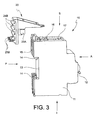
- the modular electrical equipment of the Figs. 1 , 2 , 3 comprises, by way of example, an electrical switch 10 with thermomagnetic release in the event of an overcurrent.
- the switch 10 comprises a boxed body 11 of insulating material, in which the electrical and mechanical devices are hold, of a known type, which provide to the switch functioning.
- the boxed body 11 provides two parallel planar side parts L, a front part A where a control lever 12 is located, and a rear part P for the switch mechanical and electrical connection.
- the upper and lower parts are respectively indicated with S and I.
- a coupling structure of a known type is provided in the rear part P of the switch 10 which consists in a "C"-shaped seat 13 and two opposite hooks 14 which are slidable at the "C"-shaped seat.
- a main input terminal is provided, again in the rear part P of the switch 10, which consists in a plug-in connector 15, and an output terminal, not shown, is provided in the lower part I, so shaped as a clamp; furthermore, a second input terminal is provided in the switch 10 upper part S, so shaped as a clamp 16, which can be used or not according to the type of electrical connection to be implemented. All these electrical connections are per se known in the switches of the described and illustrated type.
- a coupling notch 17 is also obtained in the upper part of the switch 10 boxed body 11, as it will be seen below.
- the switch 10 comprises a removable appendix 20, having an insulating material structure, with a squared configuration, and being mounted at an angle of the switch 10 and, particularly, it is mounted on the switch 10 rear P and upper S parts.
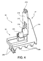
- Such appendix 20 is shown in detail in Figs. 4 , 5 , and consists in a coupling portion 21 and a contact carrier portion 22.
- the coupling portion 21 is composed by two shoulders 21A supporting a planar wall 21B having a frangible section 21C and provided, at an end thereof, with a tooth 21D.
- the portion 22 has a structure suitable to integrally receive a connector.
- a seat 22A is obtained on a side
- a turret 22B with a slit 22C communicating with the seat 22A is obtained on the other side.
- the connector is well illustrated in Figs. 7, 8 , and provides a sheet contact member 23A and a clamp contact member 23B joined by a connecting portion 23C; the contact members 23A and 23B lie on two respective contact planes which are perpendicular one to the other, and the connecting portion 23C lies on a plane which is perpendicular to the two above-mentioned contact planes.
- Such connector 23 can be made of a suitably sheared and folded lamination.
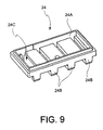
- closure member 24 well illustrated in Fig. 9 , having a general symmetrical configuration, having a seat 24A on a side, and a series of three parallel ribs 24B and a slit 24C parallel to the ribs 24B and communicating with the seat 24A on the other side.
- the connector 23 is inserted in the closure member 24 by making the clamp contact member 23B to pass through the same closure member slit 24C, then the sheet contact member 23A is made to pass into the slit 22C of the contact carrier portion 22 turret 22B, and finally the closure member 24 is snap-coupled to the contact carrier portion 22 seat 22A, thus making them integral.
- the appendix 20 frangible section 21C is located at the switch 10 clamp 16, preventing access to the same clamp. In the case when this clamp 16 has to be used, the section 21C is broken and removed, so as to give free access to the clamp.
- the clamp contact member 23B projects from the appendix 20 in a preset position, that is, the lower position in the example given. Anyhow, due to the closure member 24 symmetry, it is possible to assembly such closure member and make it integral, when it is rotated by 180° in the coupling plane, so that the clamp contact member 23B projects from the appendix 20 always in the same direction as before, but in another preset position which is parallel to the previous one, that is, the upper position in the example given.
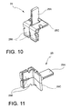
- FIG. 10 Another connector is illustrated in Figs. 10, 11 , indicated with 25, which is an alternative to the preceding connector 23. It also provides a sheet contact member, indicated with 25A, and a clamp contact member, indicated with 25B, which are joined by a connecting portion 25C.
- the contact members 25A and 25B also lie on two respective contact planes which are perpendicular one to the other, and the connecting portion 25C lies on a plane which is perpendicular to the two above-mentioned contact planes.
- the difference compared to the connector 23 is that the connecting portion 25C is shorter in the connector 25.
- Such connector 25 can also be made of a suitably sheared and folded lamination.
- the closure member will have to be slightly modified compared to the previous one, and will have a slit as the slit 24C of the closure member 24 illustrated, but at one of the two median ribs 24B, due to the connecting portion shorter length.
- the clamp contact member 25B will be able to project from the appendix 20 in one of two median preset positions compared to the lower and upper positions which have been noted for the connector 23, as a function of the arrangement in one or the other, rotated by 180°, positions, of the closure member.
- the switch 10 is intended to be mechanically mounted on a track, and electrically connected to a bar assembly, inside an electric power distribution and protection board or cabinet.
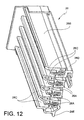
- a bar assembly 26 is illustrated in Figs. 12 , 13 , to which a series of switches 10 has to be electrically coupled, for the application in a three-phase electrical circuit.
- the bar assembly 26 consists in a series of four parallel conductor bars 26A secured to a support structure 26B of insulating material in special, essentially "U"-shaped seats 26C of the same structure.
- the seats 26C have a determined depth, and a minimal width such as to prevent fingers from accessing the conductor bars.
- the support structure comprises profiles 26D, 26E for the coupling of the same structure.
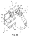
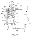
- a composite track 27 is shown in the Figs. 14 , 15 , also of a known type, on which both the switch 10 and the bar assembly 26 are mounted in a known manner.
- An essentially "C"-shaped profile 27A is formed in the track 27, to which the switch 10 is coupled; particularly, the seat 13 ( Figs. 1 , 3 ) of the switch 10 body 11 couples to the track 27 profile 27A, and the two hooks 14 ( Figs. 1 , 3 ) couple to two projections 27B of the profile 27A.
- An essentially "L"-shaped profile 27C is further formed in the track 27, to which the bar assembly 26 profiles 26D, 26E couple to the profile 27C special projections 27D.
- the described and illustrated electrical equipment turns out to be very easy as a response to the modularity need, as noted in the insertion of a structural diversification for the apparatus-bars electrical connection.
- the switch 10 remains the same, and only the appendix 20 in the closure member and the connector turns out to be slightly varied from equipment to equipment.
- the variation in the closure member is minimal in terms of position of the slit 24C through which the clamp contact member, 23B or 25B passes, and therefore it only involves two types of closure member; and the variation in the connector, 23 or 25, is also minimal, since it only involves two types of connector, the short and the long one.
- the assembling of appendix 20 on switch 10 is very easy, requiring an easy plug-in operation. Obviously, all this involves low production costs for the equipment.
- the appendix 20 replacement is likewise very easy in the event of a malfunctioning or breaking.
- the electrical safety need is also completely meet, which need involves the absence of any energized conductor members exposed at the moment when the electrical switch is disconnected from the distribution bars.
- the distribution bars 26A are not accessible from fingers, as noted above.
- the appendix 20 frangible section 21C prevents access to the clamp 16, which is typically energized.
- the general configuration of the appendix removably constrained to the body of the electrical apparatus and the parts thereof can vary, for example, as a function of the configuration of the apparatus same body and the distribution bars configuration. It shall be noted that the configuration described and illustrated above for the appendix and parts constituting it turns out to be particularly easy and functional.
- the coupling between appendix and apparatus body can also be different. Anyhow, in this case as well, the described and illustrated coupling turns out to be particularly easy and functional.
- Monopolar, bipolar, tripolar, tetrapolar systems will be able to be implemented as a function of the number of equipments which are employed.
Landscapes
- Engineering & Computer Science (AREA)
- Power Engineering (AREA)
- Connector Housings Or Holding Contact Members (AREA)
- Breakers (AREA)
- Details Of Connecting Devices For Male And Female Coupling (AREA)
Priority Applications (6)
| Application Number | Priority Date | Filing Date | Title |
|---|---|---|---|
| EP08425188.3A EP2104193B1 (de) | 2008-03-21 | 2008-03-21 | Schnellsteckvorrichtung für elektrische Module |
| PL08425188T PL2104193T3 (pl) | 2008-03-21 | 2008-03-21 | Modułowy sprzęt elektryczny do szybkiego łączenia wtykowego |
| ES08425188.3T ES2525935T3 (es) | 2008-03-21 | 2008-03-21 | Equipo eléctrico modular de enchufe rápido |
| PT84251883T PT2104193E (pt) | 2008-03-21 | 2008-03-21 | Equipamento eléctrico modular de conexão rápida |
| RU2009110381/07A RU2507655C2 (ru) | 2008-03-21 | 2009-03-20 | Быстро вставляемое модульное электрическое оборудование |
| CN2009101272977A CN101577399B (zh) | 2008-03-21 | 2009-03-20 | 快速插入式模块式电设备 |
Applications Claiming Priority (1)
| Application Number | Priority Date | Filing Date | Title |
|---|---|---|---|
| EP08425188.3A EP2104193B1 (de) | 2008-03-21 | 2008-03-21 | Schnellsteckvorrichtung für elektrische Module |
Publications (2)
| Publication Number | Publication Date |
|---|---|
| EP2104193A1 true EP2104193A1 (de) | 2009-09-23 |
| EP2104193B1 EP2104193B1 (de) | 2014-09-17 |
Family
ID=39591760
Family Applications (1)
| Application Number | Title | Priority Date | Filing Date |
|---|---|---|---|
| EP08425188.3A Active EP2104193B1 (de) | 2008-03-21 | 2008-03-21 | Schnellsteckvorrichtung für elektrische Module |
Country Status (6)
| Country | Link |
|---|---|
| EP (1) | EP2104193B1 (de) |
| CN (1) | CN101577399B (de) |
| ES (1) | ES2525935T3 (de) |
| PL (1) | PL2104193T3 (de) |
| PT (1) | PT2104193E (de) |
| RU (1) | RU2507655C2 (de) |
Cited By (4)
| Publication number | Priority date | Publication date | Assignee | Title |
|---|---|---|---|---|
| EP2408068A1 (de) * | 2010-07-16 | 2012-01-18 | Hager-Electro SAS | Konfigurierbare Überbrückungsvorrichtung |
| GB2531823A (en) * | 2015-02-05 | 2016-05-04 | Symmetrical Power Ltd | Consumer units, receptacles for consumer units and consumer unit systems |
| GB2574627A (en) * | 2018-06-13 | 2019-12-18 | Eaton Intelligent Power Ltd | Electrical panelboard and plug-in device for such a panelboard with improved electrical insulation and modularity |
| GB2579889A (en) * | 2018-10-10 | 2020-07-08 | Symmetrical Power Ltd | Consumer units |
Families Citing this family (6)
| Publication number | Priority date | Publication date | Assignee | Title |
|---|---|---|---|---|
| CN102835197B (zh) * | 2010-03-31 | 2015-12-09 | 威德米勒界面有限公司及两合公司 | 能用作总线的连接模块 |
| SG182014A1 (en) * | 2010-12-14 | 2012-07-30 | Schneider Electric South East Asia Hq Pte Ltd | Modular electrical assembly with jumper storage |
| GB2504314A (en) * | 2012-07-25 | 2014-01-29 | Schneider Electric Ltd | Electrical distribution board safety isolator |
| FR3010845B1 (fr) * | 2013-09-13 | 2015-10-16 | Schneider Electric Ind Sas | Ensemble de distribution electrique comportant un peigne multipolaire de repartition d'une energie electrique et un dispositif d'alimentation dudit peigne. |
| DE102016120412A1 (de) * | 2016-10-26 | 2018-04-26 | Knürr GmbH | Verteilerleiste |
| US10770254B2 (en) * | 2017-10-10 | 2020-09-08 | Abb Schweiz Ag | Plug-on neutral connector for use with a fault circuit interrupt circuit breaker |
Citations (5)
| Publication number | Priority date | Publication date | Assignee | Title |
|---|---|---|---|---|
| EP0472409A1 (de) * | 1990-08-21 | 1992-02-26 | Crabtree Electrical Industries Limited | Verbesserung in Bezug auf die Befestigung von Schaltgeräten |
| EP0748018A2 (de) * | 1995-06-05 | 1996-12-11 | Square D Company | Adapter für Schalter |
| EP0798835A1 (de) * | 1996-03-26 | 1997-10-01 | Bticino S.P.A. | Schalttafel und Anschlusseinrichtung für elektrische Installationen mit modularen Einrichtungen |
| WO2001029856A1 (de) * | 1999-10-18 | 2001-04-26 | Abb Patent Gmbh | Elektrischer installationsschalter |
| EP1249909A1 (de) * | 2001-04-11 | 2002-10-16 | ABB PATENT GmbH | Schnellbefestigungsvorrichtung |
Family Cites Families (6)
| Publication number | Priority date | Publication date | Assignee | Title |
|---|---|---|---|---|
| DE19504762C2 (de) * | 1995-02-04 | 2002-08-29 | Wago Verwaltungs Gmbh | Entriegelungsvorrichtung für eine Rastbefestigung eines elektr. oder elektronischen Bauelements auf einer Tragschiene |
| GB9511278D0 (en) * | 1995-06-05 | 1995-08-02 | Square D Co | Improvements in and relating to circuit breakers |
| FR2735290B1 (fr) * | 1995-06-07 | 1997-07-18 | Schneider Electric Sa | Dispositif d'assemblage et de liaison electrique d'appareils modulaires tels des disjoncteurs ou analogues |
| GB9601931D0 (en) * | 1996-01-31 | 1996-04-03 | Schneider Ltd | Improvements in and relating to electrical distribution equipment |
| DE10152347C1 (de) * | 2001-10-24 | 2003-06-12 | Siemens Ag | Schaltgerät mit adaptiertem mehrphasigem Sammelschienensystem |
| FR2834826B1 (fr) * | 2002-01-14 | 2004-10-08 | Schneider Electric Ind Sa | Dispositif de fixation amovible d'un appareil electrique sur un rail de montage et appareil electrique equipe d'un tel dispositif |
-
2008
- 2008-03-21 PL PL08425188T patent/PL2104193T3/pl unknown
- 2008-03-21 PT PT84251883T patent/PT2104193E/pt unknown
- 2008-03-21 EP EP08425188.3A patent/EP2104193B1/de active Active
- 2008-03-21 ES ES08425188.3T patent/ES2525935T3/es active Active
-
2009
- 2009-03-20 RU RU2009110381/07A patent/RU2507655C2/ru not_active IP Right Cessation
- 2009-03-20 CN CN2009101272977A patent/CN101577399B/zh not_active Expired - Fee Related
Patent Citations (5)
| Publication number | Priority date | Publication date | Assignee | Title |
|---|---|---|---|---|
| EP0472409A1 (de) * | 1990-08-21 | 1992-02-26 | Crabtree Electrical Industries Limited | Verbesserung in Bezug auf die Befestigung von Schaltgeräten |
| EP0748018A2 (de) * | 1995-06-05 | 1996-12-11 | Square D Company | Adapter für Schalter |
| EP0798835A1 (de) * | 1996-03-26 | 1997-10-01 | Bticino S.P.A. | Schalttafel und Anschlusseinrichtung für elektrische Installationen mit modularen Einrichtungen |
| WO2001029856A1 (de) * | 1999-10-18 | 2001-04-26 | Abb Patent Gmbh | Elektrischer installationsschalter |
| EP1249909A1 (de) * | 2001-04-11 | 2002-10-16 | ABB PATENT GmbH | Schnellbefestigungsvorrichtung |
Cited By (7)
| Publication number | Priority date | Publication date | Assignee | Title |
|---|---|---|---|---|
| EP2408068A1 (de) * | 2010-07-16 | 2012-01-18 | Hager-Electro SAS | Konfigurierbare Überbrückungsvorrichtung |
| FR2962861A1 (fr) * | 2010-07-16 | 2012-01-20 | Hager Electro Sas | Dispositif de pontage configurable. |
| GB2531823A (en) * | 2015-02-05 | 2016-05-04 | Symmetrical Power Ltd | Consumer units, receptacles for consumer units and consumer unit systems |
| GB2531823B (en) * | 2015-02-05 | 2016-09-21 | Symmetrical Power Ltd | Consumer units, receptacles for consumer units and consumer unit systems |
| GB2574627A (en) * | 2018-06-13 | 2019-12-18 | Eaton Intelligent Power Ltd | Electrical panelboard and plug-in device for such a panelboard with improved electrical insulation and modularity |
| GB2579889A (en) * | 2018-10-10 | 2020-07-08 | Symmetrical Power Ltd | Consumer units |
| GB2579889B (en) * | 2018-10-10 | 2021-04-28 | Symmetrical Power Ltd | Consumer units |
Also Published As
| Publication number | Publication date |
|---|---|
| RU2009110381A (ru) | 2010-09-27 |
| RU2507655C2 (ru) | 2014-02-20 |
| EP2104193B1 (de) | 2014-09-17 |
| PT2104193E (pt) | 2014-11-18 |
| PL2104193T3 (pl) | 2015-03-31 |
| CN101577399B (zh) | 2013-09-11 |
| CN101577399A (zh) | 2009-11-11 |
| ES2525935T3 (es) | 2015-01-02 |
Similar Documents
| Publication | Publication Date | Title |
|---|---|---|
| EP2104193B1 (de) | Schnellsteckvorrichtung für elektrische Module | |
| CN109494570B (zh) | 低压配电板 | |
| CN102027639B (zh) | 桥形连接器和由至少两个电接线端子和一个桥形连接器组成的结构单元 | |
| JP4046688B2 (ja) | 電源分配器及びコントロールセンタ | |
| EP1790041B1 (de) | Stromverteilungstafel | |
| US7924550B2 (en) | Multiphase line fuse module | |
| KR100973944B1 (ko) | 분전반용 플러그 | |
| KR20170085518A (ko) | 스위칭 디바이스 및 스위칭 디바이스 어레인지먼트 | |
| EP2400610B1 (de) | Stützstangen und elektrisches Verteilungsmodul mit den Stangen | |
| EP2738883A1 (de) | Verbindungsblockanordnung | |
| JP2020024962A (ja) | 開閉器及び分電盤 | |
| JP3113266U (ja) | ユニット式分電盤 | |
| CN1638222B (zh) | 将汇流条连接到配电盘的设备上的装置 | |
| JP4958282B2 (ja) | ブレーカユニット | |
| PL198225B1 (pl) | Przystawka do szafy rozdzielczej | |
| CN117039629A (zh) | 电流分配装置和包括该装置的电气配电盘 | |
| KR100607393B1 (ko) | 모듈 랙을 포함하는 스위치기어 캐비닛을 위한 연결장치 | |
| NO319544B1 (no) | Modulaert elektrisk apparat som plugges inn i en isolert distribusjonsblokk | |
| EP3375059B1 (de) | Modularer verteilungsträger für leistungsschalter | |
| JP3853064B2 (ja) | 回路遮断器の端子バリア装置 | |
| KR100635102B1 (ko) | 분,배전반용 모선부스바 | |
| RU2797997C2 (ru) | Предварительно изготовленная опора для монтируемого в стойку электрического устройства и электрическое устройство, содержащее такую опору | |
| KR200449732Y1 (ko) | 조립형 분전반용 플러그 | |
| JP2006230152A (ja) | 分電盤の幹線バー接続構造 | |
| JP2007288963A (ja) | プラグイン分電盤 |
Legal Events
| Date | Code | Title | Description |
|---|---|---|---|
| PUAI | Public reference made under article 153(3) epc to a published international application that has entered the european phase |
Free format text: ORIGINAL CODE: 0009012 |
|
| AK | Designated contracting states |
Kind code of ref document: A1 Designated state(s): AT BE BG CH CY CZ DE DK EE ES FI FR GB GR HR HU IE IS IT LI LT LU LV MC MT NL NO PL PT RO SE SI SK TR |
|
| AX | Request for extension of the european patent |
Extension state: AL BA MK RS |
|
| 17P | Request for examination filed |
Effective date: 20100202 |
|
| 17Q | First examination report despatched |
Effective date: 20100225 |
|
| AKX | Designation fees paid |
Designated state(s): AT BE BG CH CY CZ DE DK EE ES FI FR GB GR HR HU IE IS IT LI LT LU LV MC MT NL NO PL PT RO SE SI SK TR |
|
| GRAP | Despatch of communication of intention to grant a patent |
Free format text: ORIGINAL CODE: EPIDOSNIGR1 |
|
| RAP1 | Party data changed (applicant data changed or rights of an application transferred) |
Owner name: BTICINO S.P.A. |
|
| INTG | Intention to grant announced |
Effective date: 20140618 |
|
| GRAS | Grant fee paid |
Free format text: ORIGINAL CODE: EPIDOSNIGR3 |
|
| GRAA | (expected) grant |
Free format text: ORIGINAL CODE: 0009210 |
|
| AK | Designated contracting states |
Kind code of ref document: B1 Designated state(s): AT BE BG CH CY CZ DE DK EE ES FI FR GB GR HR HU IE IS IT LI LT LU LV MC MT NL NO PL PT RO SE SI SK TR |
|
| REG | Reference to a national code |
Ref country code: GB Ref legal event code: FG4D |
|
| REG | Reference to a national code |
Ref country code: CH Ref legal event code: EP |
|
| REG | Reference to a national code |
Ref country code: IE Ref legal event code: FG4D |
|
| REG | Reference to a national code |
Ref country code: AT Ref legal event code: REF Ref document number: 688067 Country of ref document: AT Kind code of ref document: T Effective date: 20141015 |
|
| REG | Reference to a national code |
Ref country code: DE Ref legal event code: R096 Ref document number: 602008034431 Country of ref document: DE Effective date: 20141030 |
|
| REG | Reference to a national code |
Ref country code: CH Ref legal event code: NV Representative=s name: JACOBACCI AND PARTNERS SA, CH |
|
| REG | Reference to a national code |
Ref country code: PT Ref legal event code: SC4A Free format text: AVAILABILITY OF NATIONAL TRANSLATION Effective date: 20141111 |
|
| REG | Reference to a national code |
Ref country code: ES Ref legal event code: FG2A Ref document number: 2525935 Country of ref document: ES Kind code of ref document: T3 Effective date: 20150102 |
|
| PG25 | Lapsed in a contracting state [announced via postgrant information from national office to epo] |
Ref country code: GR Free format text: LAPSE BECAUSE OF FAILURE TO SUBMIT A TRANSLATION OF THE DESCRIPTION OR TO PAY THE FEE WITHIN THE PRESCRIBED TIME-LIMIT Effective date: 20141218 Ref country code: LT Free format text: LAPSE BECAUSE OF FAILURE TO SUBMIT A TRANSLATION OF THE DESCRIPTION OR TO PAY THE FEE WITHIN THE PRESCRIBED TIME-LIMIT Effective date: 20140917 Ref country code: NO Free format text: LAPSE BECAUSE OF FAILURE TO SUBMIT A TRANSLATION OF THE DESCRIPTION OR TO PAY THE FEE WITHIN THE PRESCRIBED TIME-LIMIT Effective date: 20141217 Ref country code: SE Free format text: LAPSE BECAUSE OF FAILURE TO SUBMIT A TRANSLATION OF THE DESCRIPTION OR TO PAY THE FEE WITHIN THE PRESCRIBED TIME-LIMIT Effective date: 20140917 Ref country code: FI Free format text: LAPSE BECAUSE OF FAILURE TO SUBMIT A TRANSLATION OF THE DESCRIPTION OR TO PAY THE FEE WITHIN THE PRESCRIBED TIME-LIMIT Effective date: 20140917 |
|
| REG | Reference to a national code |
Ref country code: NL Ref legal event code: VDEP Effective date: 20140917 |
|
| REG | Reference to a national code |
Ref country code: LT Ref legal event code: MG4D |
|
| PG25 | Lapsed in a contracting state [announced via postgrant information from national office to epo] |
Ref country code: CY Free format text: LAPSE BECAUSE OF FAILURE TO SUBMIT A TRANSLATION OF THE DESCRIPTION OR TO PAY THE FEE WITHIN THE PRESCRIBED TIME-LIMIT Effective date: 20140917 Ref country code: HR Free format text: LAPSE BECAUSE OF FAILURE TO SUBMIT A TRANSLATION OF THE DESCRIPTION OR TO PAY THE FEE WITHIN THE PRESCRIBED TIME-LIMIT Effective date: 20140917 Ref country code: LV Free format text: LAPSE BECAUSE OF FAILURE TO SUBMIT A TRANSLATION OF THE DESCRIPTION OR TO PAY THE FEE WITHIN THE PRESCRIBED TIME-LIMIT Effective date: 20140917 |
|
| REG | Reference to a national code |
Ref country code: AT Ref legal event code: MK05 Ref document number: 688067 Country of ref document: AT Kind code of ref document: T Effective date: 20140917 |
|
| PG25 | Lapsed in a contracting state [announced via postgrant information from national office to epo] |
Ref country code: NL Free format text: LAPSE BECAUSE OF FAILURE TO SUBMIT A TRANSLATION OF THE DESCRIPTION OR TO PAY THE FEE WITHIN THE PRESCRIBED TIME-LIMIT Effective date: 20140917 |
|
| REG | Reference to a national code |
Ref country code: PL Ref legal event code: T3 |
|
| PG25 | Lapsed in a contracting state [announced via postgrant information from national office to epo] |
Ref country code: IS Free format text: LAPSE BECAUSE OF FAILURE TO SUBMIT A TRANSLATION OF THE DESCRIPTION OR TO PAY THE FEE WITHIN THE PRESCRIBED TIME-LIMIT Effective date: 20150117 Ref country code: SK Free format text: LAPSE BECAUSE OF FAILURE TO SUBMIT A TRANSLATION OF THE DESCRIPTION OR TO PAY THE FEE WITHIN THE PRESCRIBED TIME-LIMIT Effective date: 20140917 Ref country code: EE Free format text: LAPSE BECAUSE OF FAILURE TO SUBMIT A TRANSLATION OF THE DESCRIPTION OR TO PAY THE FEE WITHIN THE PRESCRIBED TIME-LIMIT Effective date: 20140917 Ref country code: CZ Free format text: LAPSE BECAUSE OF FAILURE TO SUBMIT A TRANSLATION OF THE DESCRIPTION OR TO PAY THE FEE WITHIN THE PRESCRIBED TIME-LIMIT Effective date: 20140917 Ref country code: RO Free format text: LAPSE BECAUSE OF FAILURE TO SUBMIT A TRANSLATION OF THE DESCRIPTION OR TO PAY THE FEE WITHIN THE PRESCRIBED TIME-LIMIT Effective date: 20140917 |
|
| PG25 | Lapsed in a contracting state [announced via postgrant information from national office to epo] |
Ref country code: AT Free format text: LAPSE BECAUSE OF FAILURE TO SUBMIT A TRANSLATION OF THE DESCRIPTION OR TO PAY THE FEE WITHIN THE PRESCRIBED TIME-LIMIT Effective date: 20140917 |
|
| REG | Reference to a national code |
Ref country code: DE Ref legal event code: R097 Ref document number: 602008034431 Country of ref document: DE |
|
| PLBE | No opposition filed within time limit |
Free format text: ORIGINAL CODE: 0009261 |
|
| STAA | Information on the status of an ep patent application or granted ep patent |
Free format text: STATUS: NO OPPOSITION FILED WITHIN TIME LIMIT |
|
| PG25 | Lapsed in a contracting state [announced via postgrant information from national office to epo] |
Ref country code: DK Free format text: LAPSE BECAUSE OF FAILURE TO SUBMIT A TRANSLATION OF THE DESCRIPTION OR TO PAY THE FEE WITHIN THE PRESCRIBED TIME-LIMIT Effective date: 20140917 |
|
| 26N | No opposition filed |
Effective date: 20150618 |
|
| PG25 | Lapsed in a contracting state [announced via postgrant information from national office to epo] |
Ref country code: LU Free format text: LAPSE BECAUSE OF FAILURE TO SUBMIT A TRANSLATION OF THE DESCRIPTION OR TO PAY THE FEE WITHIN THE PRESCRIBED TIME-LIMIT Effective date: 20150321 Ref country code: MC Free format text: LAPSE BECAUSE OF FAILURE TO SUBMIT A TRANSLATION OF THE DESCRIPTION OR TO PAY THE FEE WITHIN THE PRESCRIBED TIME-LIMIT Effective date: 20140917 |
|
| PG25 | Lapsed in a contracting state [announced via postgrant information from national office to epo] |
Ref country code: SI Free format text: LAPSE BECAUSE OF FAILURE TO SUBMIT A TRANSLATION OF THE DESCRIPTION OR TO PAY THE FEE WITHIN THE PRESCRIBED TIME-LIMIT Effective date: 20140917 |
|
| REG | Reference to a national code |
Ref country code: IE Ref legal event code: MM4A |
|
| PG25 | Lapsed in a contracting state [announced via postgrant information from national office to epo] |
Ref country code: IE Free format text: LAPSE BECAUSE OF NON-PAYMENT OF DUE FEES Effective date: 20150321 |
|
| REG | Reference to a national code |
Ref country code: FR Ref legal event code: PLFP Year of fee payment: 9 |
|
| PG25 | Lapsed in a contracting state [announced via postgrant information from national office to epo] |
Ref country code: MT Free format text: LAPSE BECAUSE OF FAILURE TO SUBMIT A TRANSLATION OF THE DESCRIPTION OR TO PAY THE FEE WITHIN THE PRESCRIBED TIME-LIMIT Effective date: 20140917 |
|
| REG | Reference to a national code |
Ref country code: FR Ref legal event code: PLFP Year of fee payment: 10 |
|
| PG25 | Lapsed in a contracting state [announced via postgrant information from national office to epo] |
Ref country code: BG Free format text: LAPSE BECAUSE OF FAILURE TO SUBMIT A TRANSLATION OF THE DESCRIPTION OR TO PAY THE FEE WITHIN THE PRESCRIBED TIME-LIMIT Effective date: 20140917 Ref country code: HU Free format text: LAPSE BECAUSE OF FAILURE TO SUBMIT A TRANSLATION OF THE DESCRIPTION OR TO PAY THE FEE WITHIN THE PRESCRIBED TIME-LIMIT; INVALID AB INITIO Effective date: 20080321 |
|
| REG | Reference to a national code |
Ref country code: FR Ref legal event code: PLFP Year of fee payment: 11 |
|
| PGFP | Annual fee paid to national office [announced via postgrant information from national office to epo] |
Ref country code: GB Payment date: 20200221 Year of fee payment: 13 |
|
| PGFP | Annual fee paid to national office [announced via postgrant information from national office to epo] |
Ref country code: CH Payment date: 20200221 Year of fee payment: 13 Ref country code: BE Payment date: 20200228 Year of fee payment: 13 |
|
| PGFP | Annual fee paid to national office [announced via postgrant information from national office to epo] |
Ref country code: ES Payment date: 20200401 Year of fee payment: 13 |
|
| REG | Reference to a national code |
Ref country code: DE Ref legal event code: R119 Ref document number: 602008034431 Country of ref document: DE |
|
| PG25 | Lapsed in a contracting state [announced via postgrant information from national office to epo] |
Ref country code: PT Free format text: LAPSE BECAUSE OF NON-PAYMENT OF DUE FEES Effective date: 20200921 |
|
| PG25 | Lapsed in a contracting state [announced via postgrant information from national office to epo] |
Ref country code: DE Free format text: LAPSE BECAUSE OF NON-PAYMENT OF DUE FEES Effective date: 20201001 |
|
| REG | Reference to a national code |
Ref country code: CH Ref legal event code: PL |
|
| GBPC | Gb: european patent ceased through non-payment of renewal fee |
Effective date: 20210321 |
|
| REG | Reference to a national code |
Ref country code: BE Ref legal event code: MM Effective date: 20210331 |
|
| PG25 | Lapsed in a contracting state [announced via postgrant information from national office to epo] |
Ref country code: CH Free format text: LAPSE BECAUSE OF NON-PAYMENT OF DUE FEES Effective date: 20210331 Ref country code: LI Free format text: LAPSE BECAUSE OF NON-PAYMENT OF DUE FEES Effective date: 20210331 Ref country code: GB Free format text: LAPSE BECAUSE OF NON-PAYMENT OF DUE FEES Effective date: 20210321 |
|
| REG | Reference to a national code |
Ref country code: ES Ref legal event code: FD2A Effective date: 20220523 |
|
| PGFP | Annual fee paid to national office [announced via postgrant information from national office to epo] |
Ref country code: TR Payment date: 20220224 Year of fee payment: 15 Ref country code: PL Payment date: 20220222 Year of fee payment: 15 |
|
| PG25 | Lapsed in a contracting state [announced via postgrant information from national office to epo] |
Ref country code: ES Free format text: LAPSE BECAUSE OF NON-PAYMENT OF DUE FEES Effective date: 20210322 Ref country code: BE Free format text: LAPSE BECAUSE OF NON-PAYMENT OF DUE FEES Effective date: 20210331 |
|
| PGFP | Annual fee paid to national office [announced via postgrant information from national office to epo] |
Ref country code: FR Payment date: 20230222 Year of fee payment: 16 |
|
| PG25 | Lapsed in a contracting state [announced via postgrant information from national office to epo] |
Ref country code: PL Free format text: LAPSE BECAUSE OF NON-PAYMENT OF DUE FEES Effective date: 20230321 |
|
| PG25 | Lapsed in a contracting state [announced via postgrant information from national office to epo] |
Ref country code: PL Free format text: LAPSE BECAUSE OF NON-PAYMENT OF DUE FEES Effective date: 20230321 |
|
| PG25 | Lapsed in a contracting state [announced via postgrant information from national office to epo] |
Ref country code: FR Free format text: LAPSE BECAUSE OF NON-PAYMENT OF DUE FEES Effective date: 20240331 |
|
| PG25 | Lapsed in a contracting state [announced via postgrant information from national office to epo] |
Ref country code: FR Free format text: LAPSE BECAUSE OF NON-PAYMENT OF DUE FEES Effective date: 20240331 |
|
| PGFP | Annual fee paid to national office [announced via postgrant information from national office to epo] |
Ref country code: IT Payment date: 20260219 Year of fee payment: 19 |
|
| PG25 | Lapsed in a contracting state [announced via postgrant information from national office to epo] |
Ref country code: TR Free format text: LAPSE BECAUSE OF NON-PAYMENT OF DUE FEES Effective date: 20230321 |