EP2104222A1 - Procédé et dispositif pour contrôler un moteur à courant alternatif sans balais - Google Patents
Procédé et dispositif pour contrôler un moteur à courant alternatif sans balais Download PDFInfo
- Publication number
- EP2104222A1 EP2104222A1 EP08153129A EP08153129A EP2104222A1 EP 2104222 A1 EP2104222 A1 EP 2104222A1 EP 08153129 A EP08153129 A EP 08153129A EP 08153129 A EP08153129 A EP 08153129A EP 2104222 A1 EP2104222 A1 EP 2104222A1
- Authority
- EP
- European Patent Office
- Prior art keywords
- vector
- regulating
- voltage
- motor
- stator
- Prior art date
- Legal status (The legal status is an assumption and is not a legal conclusion. Google has not performed a legal analysis and makes no representation as to the accuracy of the status listed.)
- Withdrawn
Links
- 238000000034 method Methods 0.000 title claims abstract description 26
- 239000013598 vector Substances 0.000 claims abstract description 73
- 230000001105 regulatory effect Effects 0.000 claims abstract description 57
- 230000004907 flux Effects 0.000 claims abstract description 22
- 230000001276 controlling effect Effects 0.000 claims abstract description 18
- 238000005070 sampling Methods 0.000 claims abstract description 6
- 230000006870 function Effects 0.000 claims description 7
- 230000010363 phase shift Effects 0.000 claims description 7
- 230000001131 transforming effect Effects 0.000 claims 2
- 238000006243 chemical reaction Methods 0.000 description 5
- 230000009466 transformation Effects 0.000 description 5
- 238000010586 diagram Methods 0.000 description 2
- 230000000694 effects Effects 0.000 description 2
- 230000004044 response Effects 0.000 description 2
- 230000001133 acceleration Effects 0.000 description 1
- 230000008901 benefit Effects 0.000 description 1
- 238000004364 calculation method Methods 0.000 description 1
- 239000012530 fluid Substances 0.000 description 1
- 238000004519 manufacturing process Methods 0.000 description 1
- 238000005259 measurement Methods 0.000 description 1
Images



Classifications
-
- H—ELECTRICITY
- H02—GENERATION; CONVERSION OR DISTRIBUTION OF ELECTRIC POWER
- H02P—CONTROL OR REGULATION OF ELECTRIC MOTORS, ELECTRIC GENERATORS OR DYNAMO-ELECTRIC CONVERTERS; CONTROLLING TRANSFORMERS, REACTORS OR CHOKE COILS
- H02P6/00—Arrangements for controlling synchronous motors or other dynamo-electric motors using electronic commutation dependent on the rotor position; Electronic commutators therefor
- H02P6/08—Arrangements for controlling the speed or torque of a single motor
-
- H—ELECTRICITY
- H02—GENERATION; CONVERSION OR DISTRIBUTION OF ELECTRIC POWER
- H02N—ELECTRIC MACHINES NOT OTHERWISE PROVIDED FOR
- H02N2/00—Electric machines in general using piezoelectric effect, electrostriction or magnetostriction
- H02N2/0005—Electric machines in general using piezoelectric effect, electrostriction or magnetostriction producing non-specific motion; Details common to machines covered by H02N2/02 - H02N2/16
- H02N2/0075—Electrical details, e.g. drive or control circuits or methods
-
- H—ELECTRICITY
- H02—GENERATION; CONVERSION OR DISTRIBUTION OF ELECTRIC POWER
- H02P—CONTROL OR REGULATION OF ELECTRIC MOTORS, ELECTRIC GENERATORS OR DYNAMO-ELECTRIC CONVERTERS; CONTROLLING TRANSFORMERS, REACTORS OR CHOKE COILS
- H02P25/00—Arrangements or methods for the control of AC motors characterised by the kind of AC motor or by structural details
- H02P25/02—Arrangements or methods for the control of AC motors characterised by the kind of AC motor or by structural details characterised by the kind of motor
- H02P25/022—Synchronous motors
- H02P25/03—Synchronous motors with brushless excitation
-
- H—ELECTRICITY
- H02—GENERATION; CONVERSION OR DISTRIBUTION OF ELECTRIC POWER
- H02P—CONTROL OR REGULATION OF ELECTRIC MOTORS, ELECTRIC GENERATORS OR DYNAMO-ELECTRIC CONVERTERS; CONTROLLING TRANSFORMERS, REACTORS OR CHOKE COILS
- H02P27/00—Arrangements or methods for the control of AC motors characterised by the kind of supply voltage
- H02P27/04—Arrangements or methods for the control of AC motors characterised by the kind of supply voltage using variable-frequency supply voltage, e.g. inverter or converter supply voltage
- H02P27/047—V/F converter, wherein the voltage is controlled proportionally with the frequency
-
- H—ELECTRICITY
- H02—GENERATION; CONVERSION OR DISTRIBUTION OF ELECTRIC POWER
- H02P—CONTROL OR REGULATION OF ELECTRIC MOTORS, ELECTRIC GENERATORS OR DYNAMO-ELECTRIC CONVERTERS; CONTROLLING TRANSFORMERS, REACTORS OR CHOKE COILS
- H02P27/00—Arrangements or methods for the control of AC motors characterised by the kind of supply voltage
- H02P27/04—Arrangements or methods for the control of AC motors characterised by the kind of supply voltage using variable-frequency supply voltage, e.g. inverter or converter supply voltage
- H02P27/06—Arrangements or methods for the control of AC motors characterised by the kind of supply voltage using variable-frequency supply voltage, e.g. inverter or converter supply voltage using DC to AC converters or inverters
- H02P27/08—Arrangements or methods for the control of AC motors characterised by the kind of supply voltage using variable-frequency supply voltage, e.g. inverter or converter supply voltage using DC to AC converters or inverters with pulse width modulation
-
- H—ELECTRICITY
- H02—GENERATION; CONVERSION OR DISTRIBUTION OF ELECTRIC POWER
- H02P—CONTROL OR REGULATION OF ELECTRIC MOTORS, ELECTRIC GENERATORS OR DYNAMO-ELECTRIC CONVERTERS; CONTROLLING TRANSFORMERS, REACTORS OR CHOKE COILS
- H02P6/00—Arrangements for controlling synchronous motors or other dynamo-electric motors using electronic commutation dependent on the rotor position; Electronic commutators therefor
- H02P6/10—Arrangements for controlling torque ripple, e.g. providing reduced torque ripple
Definitions
- the present invention relates to a method and device for controlling a brushless AC motor.
- devices for controlling brushless AC motors i.e. so-called permanent-magnet rotor motors
- substantially comprise an inverter which comprises a power circuit defined by six transistors arranged in pairs on three circuit branches connected to the three phases of the brushless AC motor, and a control device that instantaneously controls the six transistors to supply the three currents to the motor to generate a rotating magnetic field.
- control devices of the above type are known as “sensorless actuating devices", meaning they are able to control the power transistors with no direct measurement of the position of the rotating magnetic field of the rotor, i.e. with no sensor for measuring the instantaneous position of the rotor, which, as is known, is essential for controlling a brushless AC motor.
- Control by sensorless actuating devices substantially comprises measuring the three current supplies to the motor directly, and accordingly reconstructing the rotating magnetic field of the rotor.
- some currently used solutions employ three current-measuring devices comprising three shunts, each of which is located along a circuit branch to indicate instantaneous current flow along the branch and so permit a vector reconstruction of the stator current, by which to make a vector reconstruction of the magnetic field of the rotor.
- closed-loop regulating devices are employed which, during the uncertainty time window, impose predetermined sinusoidal current references to be followed. Use of such references by the regulating devices is unavoidable in a closed-loop control system, but, precisely on account of the circuit architecture, inevitably introduces current harmonics that increase the noise level of the motor and produce undesired torque peaks.
- a device for controlling a brushless AC motor as claimed in Claim 5 and preferably, though not necessarily, in any one of the Claims depending directly or indirectly on Claim 5.
- an electric household appliance as claimed in Claim 10.
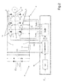
- Number 1 in Figure 1 indicates as a whole an electric household appliance comprising a casing 2, in which are housed a brushless AC motor having a permanent-magnet rotor connected to and for rotating a rotating member 4 of a device 5 about an axis A; and an electronic circuit 6 for instantaneously controlling the angular speed ⁇ of motor 3 according to a predetermined speed ⁇ '.
- electric household appliance 1 is a dishwasher
- device 5 is a fluid pump driven mechanically by motor 3.
- electronic circuit 6 comprises a first and second power line 7 at a substantially continuous supply voltage Vdc; a power circuit 8 having six transistors 9 arranged in pairs along three control circuit branches 10 connected to the first and second power line 7, and each having, between the relative pair of transistors 9, a node 11 connected to a terminal 12 of motor 3.
- Electronic circuit 6 also comprises a current-measuring module 14 located along one of the two power lines 7 to instantaneously measure the supply current Idc along power line 7.
- module 14 comprises a shunt for measuring the supply current Idc along power line 7.
- Electronic circuit 6 also comprises an open-loop control unit 15 which receives supply voltage Vdc, current Idc, and predetermined reference speed ⁇ ', and supplies control signals Scom for controlling transistors 9, and each comprising a given duty cycle enabling/disabling a respective transistor 9 of power circuit 8.
- control unit 15 substantially comprises a speed/voltage conversion module 16 which receives predetermined reference speed ⁇ ', and supplies the modulus of the theoretical voltage V' required of motor 3 to achieve predetermined reference speed ⁇ '.
- Control unit 15 also comprises an integrating module 17 which receives predetermined reference speed ⁇ ', and supplies a reference angle ⁇ '. More specifically, integrating module 17 integrates predetermined reference speed ⁇ ' to determine the required angle ⁇ ' of the rotating magnetic field of the rotor of motor 3.
- Control unit 15 also comprises a first adding node 19 which receives the modulus of reference voltage
- ; and a second adding node 20 which receives reference angle ⁇ ' and a value relative to a compensation angle ⁇ comp (described in detail below), and supplies a regulating angle ⁇ reg ⁇ '+ ⁇ comp.
- Control unit 15 also comprises a conversion module 21 which receives the modulus of regulating voltage
- Conversion module 21 also transforms vector Vr from one reference system, e.g. a polar reference system defined by a modulus and an angle, to a vector cartesian reference system ⁇ . More specifically, vector reference system ⁇ is stationary with respect to the stator, and is defined by two perpendicular axes ⁇ and ⁇ , i.e. in phase quadrature with respect to each other.
- Control unit 15 also comprises a space vector modulator 22 which receives the two voltage components V ⁇ and V ⁇ of the regulating voltage vector, and accordingly determines - in known manner not described in detail - the duty cycles of control signals Scom controlling transistors 9.
- Control unit 15 also comprises a compensation unit 23 which receives the two voltage components V ⁇ and V ⁇ , supply voltage Vdc, and supply current Idc, and supplies compensation angle ⁇ comp and the modulus of compensation voltage Vcomp.
- compensation unit 23 comprises a sampling module 24 which receives supply voltage Vdc and supply current Idc, and supplies the currents Ia, Ib, Ic supplied to motor 3.
- sampling module 24 samples supply voltage Vdc and supply current Idc by means of a known algorithm to determine the three stator currents Ia, Ib, Ic supplied to motor 3.
- Compensation unit 23 also comprises a transformation module 25 which receives the three currents Ia, Ib, Ic, and effects a direct Clark transformation on them to supply two currents I ⁇ , I ⁇ .
- the three currents Ia, Ib, Ic represent the three components of the rotating current vector I with respect to a three-phase reference system comprising three axes 120 degrees apart
- the direct Clark transformation transforms the representation of vector Ia, Ib, Ic from the above three-phase reference system to the stationary vector reference system ⁇ comprising two perpendicular axes ⁇ , and ⁇ , and in which current vector I is defined by two current components I ⁇ and I ⁇ .
- Compensation unit 23 also comprises a computing module 26 which receives currents I ⁇ , I ⁇ and the two components V ⁇ , V ⁇ of regulating voltage Vreg, and supplies a parameter RT hereinafter referred to as "quadrature error".
- quadrature error RT is a value related to the existing angular position between the space vector of stator current I and the space vector of rotor flux FluxR.
- quadrature error RT is related to the difference between a real phase shift - i.e. between the current vector represented by its components I ⁇ , I ⁇ , and the rotor flux vector represented by components FluxR ⁇ (k) and FluxR ⁇ (k) - and an optimum phase shift, in which the two vectors are substantially perpendicular.
- quadrature error RT is zero when the space vector of stator current I and the space vector of rotor flux FluxR are perpendicular - a condition corresponding to "optimum" operation of motor 3, in which the motor produces maximum torque; and is other than zero when the above perpendicular condition is not met, and which corresponds to a "delay" of the rotor flux vector with respect to the rotating stator current vector.
- Compensation unit 23 also comprises a first regulating module 28 which receives regulating error Er, and supplies compensation angle ⁇ comp.
- first regulating module 28 is a PI (proportional-integral) regulating block which determines compensation angle ⁇ comp.
- the compensation angle ⁇ comp supplied by the PI regulating block therefore enables compensation unit 23 to eliminate regulating error Er and so zero the quadrature error RT between the flux and current vectors.
- Compensation unit 23 also comprises a second regulating module 29 which receives regulating error Er, and supplies the modulus of compensation voltage Vcomp.
- second regulating module 29 is, for example, a P (proportional) regulating block or a PI (proportional-integral) regulating block, which determines compensation voltage Vcomp.
- the compensation voltage Vcomp supplied by second regulating block 29 therefore enables compensation unit 23 to eliminate regulating error Er and so zero the quadrature error RT.
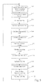
- sampling module 24 samples current Idc and voltage Vdc to determine the three currents Ia, Ib, Ic of the rotating vector of stator current Idc with respect to a three-phase reference system defined by three axis 120° apart.
- transformation module 25 effects a direct Clark transformation of the three components to determine the two components I ⁇ , I ⁇ in the stationary vector reference system ⁇ , ⁇ (block 110).
- first regulating module 28 determines compensation angle ⁇ comp at instant k.
- the compensation angle ⁇ comp(k) generated by first regulating module 28 provides for compensating variations in torque caused by fluctuations in the load of motor 3 as it is running. In this condition, in fact, the rotor flux vector tends to be slowed down by the load driven by motor 3. The method therefore compensates regulating angle ⁇ reg to bring the stator current vector rapidly back into quadrature with the rotor flux vector, which condition increases the torque of the motor to achieve a fast response to the increase in load.
- second regulating module 29 determines the modulus of compensation voltage Vcomp(k).
- the compensation voltage Vcomp(k) calculated by second regulating module 29 substantially provides for compensating the current-flux phase shift associated with the electric parameters of motor 3.
- according to the equation: Vreg(k) V'(k)+Vcomp(k).
- the method determines, by means of conversion module 21 (block 190), the two regulating voltage vector components V ⁇ (k), V ⁇ (k) according to the equations :
- V ⁇ ⁇ k Vreg k * cos ⁇ ⁇ reg k
- V ⁇ ⁇ k Vreg k * cos ⁇ ⁇ reg k
- the method determines, as a function of V ⁇ (k) and V ⁇ (k) and by means of space vector modulator 22, the duty cycles of control signals Scom to switch transistors 9 of power circuit 8 controlling the motor (block 200).
- stator flux vector FluxS ⁇ , ⁇ (k) After calculating stator flux vector FluxS ⁇ , ⁇ (k), the method repeats the above operations performed in blocks 100-220.
- the method described has the major advantage of controlling brushless AC motors simply and cheaply, and, by virtue of its open-loop configuration, introducing no noise-generating harmonics in the motor.
- compensating the motor regulating voltage angle provides, alongside fluctuations in load, for maintaining quadrature of the rotor flux and stator current, thus ensuring fast, effective response to load-induced variations in torque, which would otherwise tend to slow down rotor flux rotation, and also advantageously keeping the motor "in step".
- control by the method is particularly "robust", by ensuring correct voltage regulation regardless of the electric characteristics, i.e. parameters, of the motor. More specifically, compensating the regulating voltage modulus by tracking quadrature of the stator current and rotor flux means control of the brushless AC motor is quite insensitive of the characteristic electric parameters of the motor, thus enabling a certain amount of freedom in selection of the type of brushless AC motor employed in the appliance.
Landscapes
- Engineering & Computer Science (AREA)
- Power Engineering (AREA)
- Control Of Motors That Do Not Use Commutators (AREA)
Priority Applications (2)
| Application Number | Priority Date | Filing Date | Title |
|---|---|---|---|
| EP08153129A EP2104222A1 (fr) | 2008-03-20 | 2008-03-20 | Procédé et dispositif pour contrôler un moteur à courant alternatif sans balais |
| PCT/EP2009/002034 WO2009115330A1 (fr) | 2008-03-20 | 2009-03-19 | Procédé et dispositif de contrôle d’un moteur alternatif sans balais |
Applications Claiming Priority (1)
| Application Number | Priority Date | Filing Date | Title |
|---|---|---|---|
| EP08153129A EP2104222A1 (fr) | 2008-03-20 | 2008-03-20 | Procédé et dispositif pour contrôler un moteur à courant alternatif sans balais |
Publications (1)
| Publication Number | Publication Date |
|---|---|
| EP2104222A1 true EP2104222A1 (fr) | 2009-09-23 |
Family
ID=39791195
Family Applications (1)
| Application Number | Title | Priority Date | Filing Date |
|---|---|---|---|
| EP08153129A Withdrawn EP2104222A1 (fr) | 2008-03-20 | 2008-03-20 | Procédé et dispositif pour contrôler un moteur à courant alternatif sans balais |
Country Status (2)
| Country | Link |
|---|---|
| EP (1) | EP2104222A1 (fr) |
| WO (1) | WO2009115330A1 (fr) |
Cited By (3)
| Publication number | Priority date | Publication date | Assignee | Title |
|---|---|---|---|---|
| CN109687787A (zh) * | 2018-12-25 | 2019-04-26 | 哈尔滨工业大学 | 一种可实现过调制区域内相电流重构的方法 |
| CN111585483A (zh) * | 2020-05-28 | 2020-08-25 | 华中科技大学 | 一种开绕组永磁同步电机的相电流重构方法及控制系统 |
| WO2021118928A1 (fr) * | 2019-12-09 | 2021-06-17 | Aerovironment, Inc. | Systèmes et procédés de démarrage d'un moteur sans capteur |
Citations (6)
| Publication number | Priority date | Publication date | Assignee | Title |
|---|---|---|---|---|
| JPH03207296A (ja) * | 1990-01-09 | 1991-09-10 | Toshiba Corp | ブラシレスモータの駆動装置 |
| JP2003125594A (ja) * | 2001-10-15 | 2003-04-25 | Fuji Electric Co Ltd | 永久磁石同期電動機の制御装置 |
| EP1406375A2 (fr) * | 2002-10-01 | 2004-04-07 | Matsushita Electric Industrial Co., Ltd. | Entraíneur électrique d'un moteur et système de régulation d'entraíneur associée |
| JP2005086869A (ja) * | 2003-09-05 | 2005-03-31 | Yaskawa Electric Corp | 同期電動機の制御装置 |
| EP1542351A2 (fr) * | 2003-12-11 | 2005-06-15 | Matsushita Electric Industrial Co., Ltd. | Dispositif d'entrainement de moteur pour l'utilisation dans une lave-vaisselle |
| WO2007063766A1 (fr) * | 2005-11-30 | 2007-06-07 | Kabushiki Kaisha Yaskawa Denki | Controleur de moteur |
-
2008
- 2008-03-20 EP EP08153129A patent/EP2104222A1/fr not_active Withdrawn
-
2009
- 2009-03-19 WO PCT/EP2009/002034 patent/WO2009115330A1/fr not_active Ceased
Patent Citations (6)
| Publication number | Priority date | Publication date | Assignee | Title |
|---|---|---|---|---|
| JPH03207296A (ja) * | 1990-01-09 | 1991-09-10 | Toshiba Corp | ブラシレスモータの駆動装置 |
| JP2003125594A (ja) * | 2001-10-15 | 2003-04-25 | Fuji Electric Co Ltd | 永久磁石同期電動機の制御装置 |
| EP1406375A2 (fr) * | 2002-10-01 | 2004-04-07 | Matsushita Electric Industrial Co., Ltd. | Entraíneur électrique d'un moteur et système de régulation d'entraíneur associée |
| JP2005086869A (ja) * | 2003-09-05 | 2005-03-31 | Yaskawa Electric Corp | 同期電動機の制御装置 |
| EP1542351A2 (fr) * | 2003-12-11 | 2005-06-15 | Matsushita Electric Industrial Co., Ltd. | Dispositif d'entrainement de moteur pour l'utilisation dans une lave-vaisselle |
| WO2007063766A1 (fr) * | 2005-11-30 | 2007-06-07 | Kabushiki Kaisha Yaskawa Denki | Controleur de moteur |
Cited By (7)
| Publication number | Priority date | Publication date | Assignee | Title |
|---|---|---|---|---|
| CN109687787A (zh) * | 2018-12-25 | 2019-04-26 | 哈尔滨工业大学 | 一种可实现过调制区域内相电流重构的方法 |
| CN109687787B (zh) * | 2018-12-25 | 2020-11-24 | 哈尔滨工业大学 | 一种可实现过调制区域内相电流重构的方法 |
| WO2021118928A1 (fr) * | 2019-12-09 | 2021-06-17 | Aerovironment, Inc. | Systèmes et procédés de démarrage d'un moteur sans capteur |
| US20230017339A1 (en) * | 2019-12-09 | 2023-01-19 | Aerovironment, Inc. | Systems and methods for starting a sensorless motor |
| US12140608B2 (en) * | 2019-12-09 | 2024-11-12 | Aerovironment, Inc. | Systems and methods for starting a sensorless motor |
| AU2020399618B2 (en) * | 2019-12-09 | 2025-10-02 | Aerovironment, Inc. | Systems and methods for starting a sensorless motor |
| CN111585483A (zh) * | 2020-05-28 | 2020-08-25 | 华中科技大学 | 一种开绕组永磁同步电机的相电流重构方法及控制系统 |
Also Published As
| Publication number | Publication date |
|---|---|
| WO2009115330A1 (fr) | 2009-09-24 |
Similar Documents
| Publication | Publication Date | Title |
|---|---|---|
| KR100531455B1 (ko) | 동기전동기의 속도제어장치 | |
| US8988027B2 (en) | Motor control apparatus and motor control method | |
| JP3982232B2 (ja) | 同期発電機のセンサレス制御装置と制御方法 | |
| US7276877B2 (en) | Sensorless control method and apparatus for a motor drive system | |
| KR101376389B1 (ko) | 유도전동기용 자속 제어장치 | |
| US7193383B2 (en) | Enhanced floating reference frame controller for sensorless control of synchronous machines | |
| KR101904366B1 (ko) | 전기 구동 유닛 | |
| US20160352275A1 (en) | Temperature estimating apparatus for synchronous motor | |
| US7187155B2 (en) | Leakage inductance saturation compensation for a slip control technique of a motor drive | |
| EP3070836B1 (fr) | Procédés de syntonisation automatique de paramètres de machine et systèmes associés | |
| US10644627B2 (en) | Control device of synchronous electric motor, integrated motor system, pump system, and positioning system | |
| US11764710B2 (en) | Automatic transition of motor controller from open-loop control to closed-loop control | |
| US6301136B1 (en) | Floating flame controller | |
| US8975842B2 (en) | Permanent magnet motor control | |
| EP2104222A1 (fr) | Procédé et dispositif pour contrôler un moteur à courant alternatif sans balais | |
| CN112740534A (zh) | 多电机变换器 | |
| KR20070107998A (ko) | 동기 릴럭턴스 모터의 제어 장치 및 방법 | |
| CN111162709A (zh) | 电机驱动控制方法、装置、系统及家电设备 | |
| CN105359404B (zh) | 用于无传感器式地获知电机的转子位置的方法和装置 | |
| JP4535082B2 (ja) | 同期発電機のセンサレス制御装置と制御方法 | |
| CN119678362A (zh) | 永磁同步电动机的驱动装置和控制方法 | |
| EP1218754A1 (fr) | Comparaison de courants de couple pour diagnostics de vraisemblance de courant dans une machine electrique a aimant permanent | |
| Casadei et al. | Performance analysis of a speed sensorless induction motor drive based on a constant switching frequency DTC scheme | |
| WO2012127236A2 (fr) | Système de commande pour onduleur, et procédé de commande d'un onduleur | |
| KR101694167B1 (ko) | 동기 전동기의 위치 추정 방법 및 이를 이용한 전동기 구동장치 |
Legal Events
| Date | Code | Title | Description |
|---|---|---|---|
| PUAI | Public reference made under article 153(3) epc to a published international application that has entered the european phase |
Free format text: ORIGINAL CODE: 0009012 |
|
| AK | Designated contracting states |
Kind code of ref document: A1 Designated state(s): AT BE BG CH CY CZ DE DK EE ES FI FR GB GR HR HU IE IS IT LI LT LU LV MC MT NL NO PL PT RO SE SI SK TR |
|
| AX | Request for extension of the european patent |
Extension state: AL BA MK RS |
|
| 17P | Request for examination filed |
Effective date: 20100322 |
|
| AKX | Designation fees paid |
Designated state(s): AT BE BG CH CY CZ DE DK EE ES FI FR GB GR HR HU IE IS IT LI LT LU LV MC MT NL NO PL PT RO SE SI SK TR |
|
| GRAP | Despatch of communication of intention to grant a patent |
Free format text: ORIGINAL CODE: EPIDOSNIGR1 |
|
| RAP1 | Party data changed (applicant data changed or rights of an application transferred) |
Owner name: ELECTROLUX HOME PRODUCTS CORPORATION N.V. |
|
| STAA | Information on the status of an ep patent application or granted ep patent |
Free format text: STATUS: THE APPLICATION IS DEEMED TO BE WITHDRAWN |
|
| 18D | Application deemed to be withdrawn |
Effective date: 20101021 |