EP2104294A2 - Surveillance d'un canal de contrôle dans un système de communication sans fil - Google Patents
Surveillance d'un canal de contrôle dans un système de communication sans fil Download PDFInfo
- Publication number
- EP2104294A2 EP2104294A2 EP09004042A EP09004042A EP2104294A2 EP 2104294 A2 EP2104294 A2 EP 2104294A2 EP 09004042 A EP09004042 A EP 09004042A EP 09004042 A EP09004042 A EP 09004042A EP 2104294 A2 EP2104294 A2 EP 2104294A2
- Authority
- EP
- European Patent Office
- Prior art keywords
- cce
- search space
- aggregation level
- cces
- starting location
- Prior art date
- Legal status (The legal status is an assumption and is not a legal conclusion. Google has not performed a legal analysis and makes no representation as to the accuracy of the status listed.)
- Granted
Links
Images







Classifications
-
- H—ELECTRICITY
- H04—ELECTRIC COMMUNICATION TECHNIQUE
- H04W—WIRELESS COMMUNICATION NETWORKS
- H04W48/00—Access restriction; Network selection; Access point selection
- H04W48/08—Access restriction or access information delivery, e.g. discovery data delivery
- H04W48/12—Access restriction or access information delivery, e.g. discovery data delivery using downlink control channel
-
- H—ELECTRICITY
- H04—ELECTRIC COMMUNICATION TECHNIQUE
- H04L—TRANSMISSION OF DIGITAL INFORMATION, e.g. TELEGRAPHIC COMMUNICATION
- H04L27/00—Modulated-carrier systems
- H04L27/26—Systems using multi-frequency codes
- H04L27/2601—Multicarrier modulation systems
- H04L27/2647—Arrangements specific to the receiver only
- H04L27/2655—Synchronisation arrangements
- H04L27/2656—Frame synchronisation, e.g. packet synchronisation, time division duplex [TDD] switching point detection or subframe synchronisation
-
- H—ELECTRICITY
- H04—ELECTRIC COMMUNICATION TECHNIQUE
- H04L—TRANSMISSION OF DIGITAL INFORMATION, e.g. TELEGRAPHIC COMMUNICATION
- H04L27/00—Modulated-carrier systems
- H04L27/26—Systems using multi-frequency codes
- H04L27/2601—Multicarrier modulation systems
- H04L27/2602—Signal structure
- H04L27/261—Details of reference signals
-
- H—ELECTRICITY
- H04—ELECTRIC COMMUNICATION TECHNIQUE
- H04L—TRANSMISSION OF DIGITAL INFORMATION, e.g. TELEGRAPHIC COMMUNICATION
- H04L5/00—Arrangements affording multiple use of the transmission path
- H04L5/003—Arrangements for allocating sub-channels of the transmission path
- H04L5/0053—Allocation of signalling, i.e. of overhead other than pilot signals
-
- H—ELECTRICITY
- H04—ELECTRIC COMMUNICATION TECHNIQUE
- H04L—TRANSMISSION OF DIGITAL INFORMATION, e.g. TELEGRAPHIC COMMUNICATION
- H04L5/00—Arrangements affording multiple use of the transmission path
- H04L5/0091—Signalling for the administration of the divided path, e.g. signalling of configuration information
-
- H—ELECTRICITY
- H04—ELECTRIC COMMUNICATION TECHNIQUE
- H04W—WIRELESS COMMUNICATION NETWORKS
- H04W24/00—Supervisory, monitoring or testing arrangements
Definitions
- the present invention relates to wireless communications, and more particularly, to a method and apparatus of monitoring a control channel to effectively detect control information.
- a base station provides services to a plurality of user equipments (UEs).
- the BS schedules user data on the plurality of UEs, and transmits control information together with the user data.
- the control information contains scheduling information regarding the user data.
- a channel for carrying the control information is generally referred to as a control channel.
- a channel for carrying the user data is generally referred to as a data channel.
- the UE monitors the control channel to find control information of the UE, and processes data of the UE by using the control information. Monitoring is an operation in which the UE attempts to decode control channel candidates.
- the control information regarding the user data on the control channel must be received.
- a plurality of pieces of control information of the plurality of UEs are multiplexed within one transmission interval in a given bandwidth. That is, to provide a service to the plurality of UEs, the BS multiplexes the plurality of pieces of control information of the plurality of UEs and transmits the control information through a plurality of control channels.
- Each UE finds its own control channel from the plurality of control channels.
- Blind decoding is one of schemes for detecting specific control information from a plurality of pieces of multiplexed control information.
- the blind decoding is performed by the UE to recover a control channel by combining a plurality of pieces of information in a state where information required to recover the control channel does not exist. That is, in a state where the UE neither knows whether a plurality of pieces of control information received from the BS is control information of the UE nor knows in which location the control information of the UE exists, the UE decodes all pieces of provided control information until the control information of the UE is detected. The UE may use its unique information to determine whether the received control information is control information of the UE.
- the BS may transmit a unique identifier of each UE by masking the identifier onto a cyclic redundancy check (CRC).
- CRC is a code used in error detection.
- the UE demasks its unique identifier with the CRC of the received control information, and thereafter can determine whether the received control information is control information of the UE by performing CRC checking.
- the UE does not correctly detect its control information from the plurality of pieces of multiplexed control information, the UE cannot decode user data on a data channel. Therefore, it can be said that rapid and accurate detection on control information has a significant effect on overall system performance. However, it may be difficult to detect the control information by using only simple blind decoding.
- Each UE may require different control information and may use a channel encoding scheme using a different code rate.
- a size of control information may be different from one UE to another. Consequently, the number of blind decoding attempts may be unexpectedly increased in a control region where control information is transmitted. Battery consumption of the UE increases in proportion to the number of detection attempts.
- the present invention provides a method and apparatus of effectively monitoring a control channel.
- a method of monitoring a physical downlink control channel (PDCCH) in a wireless communication system includes acquiring a starting location of a search space in a control region of a subframe k, the control region comprising a set of contiguous control channel elements (CCEs) numbered from 0 to N CCE,k -1, where N CCE,k is the total number of CCEs in the control region of the subframe k, wherein the search space is defined by a set of PDCCHs at each aggregation level, the each aggregation level indicating an aggregation of contiguous CCEs, wherein the starting location corresponding to a CCE index is defined by the multiple of the aggregation level in the control region, and monitoring the set of PDCCHs from the starting location in the search space at the each aggregation level.
- CCEs contiguous control channel elements
- the search space may be a UE specific search space which is monitored by at least one UE in a cell.
- the set of PDCCHs may be monitored in the unit of the aggregation level in the search space.
- a user equipment in another aspect, includes a Radio Frequency (RF) unit for transmitting and receiving radio signals, and a processor coupled with the RF unit and configured to acquire a starting location of a search space in a control region of a subframe k, the control region comprising a set of contiguous control channel elements (CCEs) numbered from 0 to N CCE,k -1, where N CCE,k is the total number of CCEs in the control region of the subframe k, wherein the search space is defined by a set of PDCCHs at each aggregation level, the each aggregation level indicating an aggregation of contiguous CCEs, wherein the starting location corresponding to a CCE index is defined by the multiple of the aggregation level in the control region, and monitor the set of PDCCHs from the starting location in the search space at the each aggregation level.
- RF Radio Frequency
- a method of monitoring a physical downlink control channel (PDCCH) in a wireless communication system includes acquiring a starting location of a search space in a control region of a subframe, the control region comprising a set of contiguous control channel elements (CCEs), wherein the search space is defined by a set of PDCCHs at each aggregation level, the each aggregation level indicating an aggregation of contiguous CCEs, wherein the starting location is defined according to the aggregation level in the control region, and monitoring the set of PDCCHs from the starting location in the search space at the each aggregation level.
- CCEs contiguous control channel elements
- the set of contiguous CCEs in the control region may be numbered from 0 to N CCE -1, where N CCE is the total number of CCEs in the control region.
- the starting location corresponding to a CCE index may be defined by the multiple of the aggregation level in the control region.
- the set of contiguous CCEs in the control region may be divided into ⁇ N CCE L ⁇ aggregated CCE units, where N CCE is the total number of CCEs in the control region and L is the aggregation level.
- the starting location may be one CCE in an aggregated CCE unit selected from the aggregated CCE units.
- the starting location may be the first CCE in the aggregated CCE unit selected from the aggregated CCE units.
- the aggregated CCE units may be numbered from 0 to ⁇ N CCE L ⁇ - 1 .
- the first CCEs in the aggregated CCE units may be numbered from 0 to ⁇ N CCE L ⁇ - 1 .
- a user equipment can effectively monitor a downlink control channel.
- a base station BS can effectively multiplex and transmit a plurality of control channels for carrying control information regarding a plurality of UEs. Therefore, the number of detection attempts depending on blind decoding for monitoring the downlink control channel can be reduced. An overhead caused by blind decoding is reduced, and a time for finding the downlink control channel required by the UE is reduced. A battery consumption of the UE is reduced, and overall system performance can be improved.
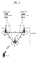
- FIG. 1 shows a structure of a wireless communication system.
- the wireless communication system may have a network structure of an evolved-universal mobile telecommunications system (E-UMTS).
- E-UMTS evolved-universal mobile telecommunications system
- LTE long term evolution
- the wireless communication system can be widely deployed to provide a variety of communication services, such as voices, packet data, etc.
- an evolved-UMTS terrestrial radio access network includes at least one base station (BS) 20 which provides a control plane and a user plane.
- BS base station
- a user equipment (UE) 10 may be fixed or mobile, and may be referred to as another terminology, such as a mobile station (MS), a user terminal (UT), a subscriber station (SS), a wireless device, etc.
- the BS 20 is generally a fixed station that communicates with the UE 10 and may be referred to as another terminology, such as an evolved node-B (eNB), a base transceiver system (BTS), an access point, etc.
- eNB evolved node-B
- BTS base transceiver system
- the cell is a region in which the BS 20 provides a communication service. Interfaces for transmitting user traffic or control traffic may be used between the BSs 20.
- a downlink is defined as a communication link from the BS 20 to the UE
- an uplink is defined as a communication link from the UE 10 to the BS 20.
- the BSs 20 are interconnected by means of an X2 interface.
- the BSs 20 are also connected by means of an S1 interface to an evolved packet core (EPC), more specifically, to a mobility management entity (MME)/serving gateway (S-GW) 30.
- EPC evolved packet core
- MME mobility management entity
- S-GW serving gateway
- FIG. 2 is a block diagram showing functional split between the E-UTRAN and the EPC. Slashed boxes depict radio protocol layers and white boxes depict the functional entities of the control plane.
- the BS performs the following functions: (1) functions for radio resource management (RRM) such as radio bearer control, radio admission control, connection mobility control, and dynamic allocation of resources to the UE; (2) Internet protocol (IP) header compression and encryption of user data streams; (3) routing of user plane data to the S-GW; (4) scheduling and transmission of paging messages; (5) scheduling and transmission of broadcast information; and (6) measurement and measurement reporting configuration for mobility and scheduling.
- RRM radio resource management
- IP Internet protocol
- the MME performs the following functions: (1) non-access stratum (NAS) signaling; (2) NAS signaling security; (3) idle mode UE reachability; (4) tracking area list management; (5) roaming; and (6) authentication.
- NAS non-access stratum
- the S-GW performs the following functions: (1) mobility anchoring; and (2) lawful interception.
- a PDN gateway performs the following functions: (1) UE IP allocation; and (2) packet filtering.
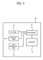
- FIG. 3 is a block diagram showing an user equipment for implementing monitoring of control channel.
- a UE 50 includes a processor 51, a memory 52, a radio frequency (RF) unit 53, a display unit 54, and a user interface unit 55. Layers of the radio interface protocol are implemented in the processor 51. The function of each layer can be implemented in the processor 51.
- the processor 51 having a physical layer may implement monitoring of a control channel disclosed herein.
- the memory 52 is coupled to the processor 51 and stores various parameters for operating the processor 51.
- the display unit 54 displays a variety of information of the apparatus 50 and may use a well-known element such as a liquid crystal display (LCD), an organic light emitting diode (OLED), etc.
- the user interface unit 55 can be configured with a combination of well-known user interfaces such as a keypad, a touch screen, etc.
- the RF unit 53 is coupled to the processor 51 and transmits and/or receives radio signals.
- Layers of a radio interface protocol between the UE and the network can be classified into a first layer (L1), a second layer (L2), and a third layer (L3) based on the lower three layers of the open system interconnection (OSI) model that is well-known in the communication system.
- a physical layer, or simply a PHY layer belongs to the first layer and provides an information transfer service through a physical channel.
- a radio resource control (RRC) layer belongs to the third layer and serves to control radio resources between the UE and the network. The UE and the network exchange RRC messages via the RRC layer.
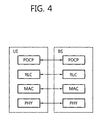
- FIG. 4 is a diagram showing a radio protocol architecture for the user plane.
- FIG. 5 is a diagram showing a radio protocol architecture for the control plane. They illustrate the architecture of a radio interface protocol between the UE and the E-UTRAN.
- the user plane is a protocol stack for user data transmission.
- the control plane is a protocol stack for control signal transmission.
- a PHY layer belongs to the first layer and provides an upper layer with an information transfer service through a physical channel.
- the PHY layer is coupled with a medium access control (MAC) layer, i.e., an upper layer of the PHY layer, through a transport channel.
- MAC medium access control
- Data is transferred between the MAC layer and the PHY layer through the transport channel.
- PHY layers i.e., a PHY layer of a transmitter and a PHY layer of a receiver
- the MAC layer belongs to the second layer and provides services to a radio link control (RLC) layer, i.e., an upper layer of the MAC layer, through a logical channel.
- RLC radio link control
- the RLC layer in the second layer supports reliable data transfer.
- There are three operating modes in the RLC layer that is, a transparent mode (TM), an unacknowledged mode (UM), and an acknowledged mode (AM) according to a data transfer method.
- TM transparent mode
- UM unacknowledged mode
- AM acknowledged mode
- An AM RLC provides bidirectional data transmission services and supports retransmission when the transfer of the RLC protocol data unit (PDU) fails.
- a packet data convergence protocol (PDCP) layer belongs to the second layer and performs a header compression function for reducing an IP packet header size.
- PDCP packet data convergence protocol
- a radio resource control (RRC) layer belongs to the third layer and is defined only in the control plane.
- the RRC layer serves to control the logical channel, the transport channel, and the physical channel in association with configuration, reconfiguration and release of radio bearers (RBs).
- An RB is a service provided by the second layer for data transmission between the UE and the E-UTRAN.
- a non-access stratum (NAS) layer belongs to an upper layer of the RRC layer and serves to perform session management, mobility management, or the like.
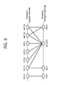
- FIG. 6 shows mapping between downlink logical channels and downlink transport channels. This may be found in section 6.1.3.2 of the 3GPP TS 36.300 V8.3.0 (2007-12) Technical Specification Group Radio Access Network; Evolved Universal Terrestrial Radio Access (E-UTRA) and Evolved Universal Terrestrial Radio Access Network (E-UTRAN); Overall description; Stage 2 (Release 8).
- E-UTRA Evolved Universal Terrestrial Radio Access
- E-UTRAN Evolved Universal Terrestrial Radio Access Network
- a paging control channel is mapped to a paging channel (PCH).
- a broadcast control channel (BCCH) is mapped to a broadcast channel (BCH) or a downlink shared channel (DL-SCH).
- a common control channel (CCCH), a dedicated control channel (DCCH), a dedicated traffic channel (DTCH), a multicast control channel (MCCH), and a multicast traffic channel (MTCH) are mapped to the DL-SCH.
- the MCCH and MTCH are also mapped to a multicast channel (MCH).
- a type of each logical channel is defined according to a type of information to be transmitted.
- a logical channel is classified into two groups, i.e., a control channel and a traffic channel.
- the control channel is used for the transfer of control plane information.
- the BCCH is a downlink channel for broadcasting system control information.
- the PCCH is a downlink channel for transmitting paging information and is used when a network does not know the location of a UE.
- the CCCH is a channel for transmitting control information between the UE and the network and is used when there is no RRC connection established between the UE and the network.
- the MCCH is a point-to-multipoint downlink channel used for transmitting multimedia broadcast multicast service (MBMS) control information.
- the MCCH is used by UEs that receive an MBMS.
- the DCCH is a point-to-point unidirectional channel for transmitting dedicated control information between the UE and the network, and is used by UEs having an RRC connection.
- the traffic channel is used for the transfer of user plane information.
- the DTCH is a point-to-point channel used for the transfer of user information.
- the DTCH can exist in both uplink and downlink.
- the MTCH is a point-to-multipoint downlink channel for transmitting traffic data and is used by the UEs that receive the MBMS.
- the transport channel is classified according to a type and characteristic of data transmission through a radio interface.
- the BCH is broadcast in the entire coverage area of the cell and has a fixed, pre-defined transport format.
- the DL-SCH is characterized by support for hybrid automatic repeat request (HARQ), support for dynamic link adaptation by varying modulation, coding, and transmit power, possibility to be broadcast in the entire cell, and possibility to use beamforming, support for both dynamic and semi-static resource allocation, support for UE discontinuous reception (DRX) to enable UE power saving, and support for MBMS transmission.
- the PCH is characterized by support for DRX to enable UE power saving and support for broadcast in the entire coverage area of the cell.
- the MCH is characterized by support for broadcast in the entire coverage area of the cell and support for an MBMS single frequency network (MBSFN).
- FIG. 7 shows mapping between downlink transport channels and downlink physical channels. This may be found in section 5.3.1 of the 3GPP TS 36.300 V8.3.0 (2007-12).
- a BCH is mapped to a physical broadcast channel (PBCH).
- An MCH is mapped to a physical multicast channel (PMCH).
- a PCH and a DL-SCH are mapped to a physical downlink shared channel (PDSCH).
- the PBCH carries a BCH transport block.
- the PMCH carries the MCH.
- the PDSCH carries the DL-SCH and the PCH.
- a physical downlink control channel informs a UE of resource allocation of the PCH and DL-SCH, and also informs the UE of HARQ information related to the DL-SCH.
- the PDCCH may carry an uplink scheduling grant which informs the UE of resource allocation for uplink transmission.
- a physical control format indicator channel informs the UE of the number of orthogonal frequency division multiplexing (OFDM) symbols used for the transfer of PDCCHs in a subframe. The PCFICH is transmitted in every subframe.
- a physical hybrid ARQ indicator channel PHICH) carries HARQ acknowledgement (ACK)/negative-acknowledgement (NACK) signals in response to uplink transmission.
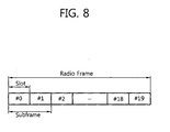
- FIG. 8 shows a structure of a radio frame.
- the radio frame includes 10 subframes.
- One subframe includes two slots.
- a time for transmitting one subframe is defined as a transmission time interval (TTI).
- TTI transmission time interval
- one subframe may have a length of 1 milliseconds (ms), and one slot may have a length of 0.5 ms.
- the radio frame of FIG. 8 is shown for exemplary purposes only.
- the number of subframes included in the radio frame or the number of slots included in the subframe or the number of OFDM symbols included in the slot may change variously.
- FIG. 9 shows an example of a resource grid for one downlink slot.
- the downlink slot includes a plurality of OFDM symbols in a time domain. Although it is described herein that one downlink slot includes 7 OFDM symbols in the time domain and one resource block includes 12 subcarriers in a frequency domain, this is for exemplary purposes only, and thus the present invention is not limited thereto.
- resource elements Elements on the resource grid are referred to as resource elements (RE).
- One resource block includes 12x7 resource elements.
- the number N DL of resource blocks included in the downlink slot depends on a downlink transmission bandwidth determined in a cell.
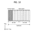
- FIG. 10 shows a structure of a subframe.
- a subframe includes two consecutive slots.
- a maximum of three OFDM symbols located in a front portion of a first slot within the subframe correspond to a control region to be assigned with one or more PDCCHs.
- the remaining OFDM symbols correspond to a data region to be assigned with one or more PDSCHs.
- control channels such as a PCFICH, a PHICH, etc., can be assigned to the control region.
- the UE can read data information transmitted through the PDSCH by decoding control information transmitted through the PDCCH.
- the control region includes three OFDM symbols herein, this is for exemplary purposes only.
- the number of OFDM symbols included in the control region of the subframe can be known by using the PCFICH.
- the control region consists of a plurality of control channel elements (CCEs), i.e., a logical CCE stream.
- CCEs control channel elements
- the CCE stream denotes a set of all CCEs constituting the control region in one subframe.
- the CCE corresponds to a plurality of resource element groups.
- the CCE may correspond to 9 resource element groups.
- the resource element group is used to define mapping of a control channel onto a resource element.
- one resource element group may consist of four resource elements.
- a plurality of PDCCHs may be transmitted in the control region.
- the PDCCH carries control information such as scheduling allocation.
- the PDCCH is transmitted on an aggregation of one or several consecutive CCEs.
- a PDCCH format and the number of available PDCCH bits are determined according to the number of CCEs constituting the CCE aggregation.
- the number of CCEs used for PDCCH transmission is referred to as a CCE aggregation level.
- the CCE aggregation level is a CCE unit for searching for the PDCCH.
- a size of the CCE aggregation level is defined by the number of contiguous CCEs.
- the CCE aggregation level may be an element of ⁇ 1, 2,4,8 ⁇ .
- Table 1 shows examples of the PDCCH format and the number of available PDCCH bits according to the CCE aggregation level.
- PDCCH format CCE aggregation level Number of resource element groups Number of PDCCH bits 0 1 9 72 1 2 18 144 2 4 36 288 3 8 72 576
- DCI downlink control information
- the DCI transmits uplink or downlink scheduling information, an uplink power control command, control information for paging, control information for indicating a random access channel (RACH) response, etc.
- RACH random access channel
- Examples of a DCI format include a format 0 for scheduling of a physical uplink shared channel (PUSCH), a format 1 for scheduling of one physical downlink shared channel (PDSCH) codeword, a format 1A for compact scheduling of the one PDSCH codeword, a format 1C for significantly compact scheduling of a downlink shared channel (DL-SCH), a format 2 for scheduling of the PDSCH in a closed-loop spatial multiplexing mode, a format 2A for scheduling of the PDSCH in an open-loop spatial multiplexing mode, and formats 3 and 3A for transmission of a transmission power control (TPC) command for an uplink channel.
- PUSCH physical uplink shared channel
- PDSCH physical downlink shared channel
- a format 1A for compact scheduling of the one PDSCH codeword
- a format 1C for significantly compact scheduling of a downlink shared channel
- DL-SCH downlink shared channel
- a format 2 for scheduling of the PDSCH in a closed-loop spatial multiplexing mode a format 2A
- FIG. 11 is a flowchart showing a PDCCH configuration.
- a BS appends a cyclic redundancy check (CRC) to a DCI to be sent to a UE so as to detect an error.
- An identifier i.e., a radio network temporary identifier (RNTI)
- RNTI radio network temporary identifier
- a unique identifier e.g., cell-RNTI (C-RNTI) of the UE can be masked on the CRC.
- a paging identifier e.g., paging-RNTI (P-RNTI)
- P-RNTI paging-RNTI
- SI-RNTI system information-RNTI
- RA-RNTI random access-RNTI
- Table 2 Type Identifier Description UE-specific C-RNTI used for a unique UE identification Common P-RNTI used for paging message SI-RNTI used for system information RA-RNTI used for random access response When the C-RNTI is used, the PDCCH carries control information for a corresponding specific UE. When other RNTIs are used, the PDCCH carries common control information received by all UEs in a cell.
- step S 120 channel coding is performed on the CRC-appended control information to generate coded data.
- step S 130 rate matching is performed according to a CCE aggregation level assigned to the PDCCH format.
- step S 140 the coded data is modulated to generate modulation symbols.
- the number of modulation symbols constituting one PDCCH may differ according to the CCE aggregation level (i.e., one of 1, 2, 4, and 8).
- step S 150 the modulation symbols are mapped to physical resource elements (REs) (i.e., CCE to RE mapping).
- REs physical resource elements
- a plurality of PDCCHs can be transmitted in one subframe.
- the UE obtains a logical CCE stream by demapping one or more physical resource elements constituting a control region of one subframe (i.e., CCE to RE demapping).
- the UE monitors the PDCCHs in the CCE stream. Monitoring is an operation in which the UE attempts to decode each PDCCH according to a DCI format to be monitored.
- the BS does not provide information indicating where a PDCCH corresponding to the UE is located in the CCE stream.
- the UE finds its PDCCH by monitoring a set of PDCCH candidates in the CCE stream. This is called blind detection.
- a CRC error is not detected as a result of CRC checking after demasking a C-RNTI of the UE with a corresponding PDCCH, it is regarded that the PDCCH of the UE is detected by the UE.
- the UE monitors the set of PDCCH candidates in every subframe to receive data transmitted to the UE.
- the UE wakes up in a monitoring duration of each DRX period and monitors the set of PDCCH candidates in a subframe corresponding to the monitoring duration.
- the subframe at which the PDCCH is monitored is called a non-DRX subframe.
- the UE has to perform blind decoding on all CCEs of a non-DRX subframe. Since the UE does not know a format of the transmitted PDCCH, the UE has to decode all PDCCHs at a possible CCE aggregation level until blind decoding on the PDCCH is successfully achieved in every non-DRX subframe.
- FIG. 12 shows an example of control channel monitoring.
- the total number of CCEs in a corresponding subframe is N CCE .
- the UE attempts blind decoding for all of four RNTIs (i.e., C-RNTI, P-RNTI, SI-RNTI, and RA-RNTI). Furthermore, the UE attempts blind decoding for all DCI formats to be monitored.
- RNTIs i.e., C-RNTI, P-RNTI, SI-RNTI, and RA-RNTI.
- the PDCCH can be limitedly allocated on the CCE stream at a specific position, a specific starting location, or a specific range.
- the UE can search for the PDCCH by simply performing blind decoding only at the specific position, the specific starting location, or the specific range. Therefore, the number of detection attempts for blind coding can be reduced.
- the specific range on the CCE stream is defined as a search space.
- the search space is a space for searching for a PDCCH on a logical CCE stream.
- a set of PDCCH candidates to be monitored is defined according to the search space.
- the search space is a set of continuous CCEs from a specific starting location within the CCE stream according to the CCE aggregation level.
- the search space is defined according to each CCE aggregation level.
- the PDCCH candidates are independently located for each CCE aggregation level. That is, the specific starting location where the PDCCH can be located may differ according to each CCE aggregation level.
- the control information carried on the PDCCH can be classified into common control information received by all UEs in a cell and UE-specific control information received by a specific UE in the cell.
- the BS multiplexes and transmits the common control information and the UE-specific control information regarding the plurality of UEs. Therefore, the search space can be divided into a common search space for the common control information and a UE-specific search space for the UE-specific control information.
- the common search space is allocated with a PDCCH carrying the common control information.
- the number of detection attempts can be reduced when the UE attempts blind decoding on a set of PDCCH candidates carrying the common control information only within the common search space.
- Examples of the common control information include control information for paging message, control information for system information, control information for system information modification, control information for random access response, etc.
- a CRC may be masked with an RNTI for each common control information.
- the CRC may be masked with P-RNTI, SI-RNTI, RA-RNTI, etc., according to each common control information.
- the common search space may be different from one subframe to another, or may be the same in every subframe.
- a starting location of the common search space is the same for all UEs in a cell. That is, the starting location of the common search space is fixed to all UEs in the cell. The starting location of the common search space may be the same for all cells. Alternatively, to randomize inter-cell interference, a starting location of a different common search space may be determined for each cell. The starting location of the common search space may be predetermined between the BS and the UE, or may be reported by the BS to the UE through RRC signaling or system information.
- the UE-specific search space is allocated with a PDCCH carrying the UE-specific control information.
- the number of detection attempts can be reduced when the UE attempts blind decoding on a set of PDCCH candidates carrying the UE-specific control information only within the UE-specific search space.
- the UE finds a starting location of the UE-specific search space and then attempts blind decoding on the set of PDCCH candidates carrying the UE-specific control information from the starting location.
- the starting location of the UE-specific search space may differ for each UE, each subframe, and each CCE aggregation level.
- Examples of the UE-specific control information include uplink scheduling allocation information and downlink scheduling allocation information on a specific UE.
- the UE-specific control information allocated to the UE-specific search space may be limited to UE-specific control information having a relatively long information payload length.
- the payload length changes semi-statically in uplink scheduling allocation or downlink scheduling allocation for single input multiple output (SIMO)/multiple input multiple output (MIMO) operations. Therefore, in the UE-specific search space in a subframe, blind decoding is performed in accordance with a payload format corresponding to a transport mode used in the subframe.
- the CRC can be masked with the C-RNTI.
- a hashing function can be implemented in the UE.
- the hashing function is a function for specifying the starting location of the UE-specific search space.
- the hashing function can use inputs such as a UE identifier (ID), a CCE aggregation level, a subframe number, the number of available CCEs of a corresponding subframe, a specific constant, etc.
- ID UE identifier
- CCE aggregation level e.g., a CCE aggregation level
- subframe number e.g., the number of available CCEs of the corresponding subframe
- the hashing function may output the starting location of the UE-specific search space as a CCE index number on a set of CCEs.
- the common search space is a search space monitored by all UEs in a cell
- the UE-specific search space is a search space monitored by a specific UE.
- the UE monitors both the common search space and the UE-specific search space.
- the common search space may overlap with the UE-specific search space.
- the starting location of the UE-specific search space can be output by the hashing function, which will be described hereinafter.
- all CCEs on a CCE stream can be the starting location of the UE-specific search space. For example, if the total number of CCEs constituting a logical CCE stream in a k-th subframe is N CCE,K , the number of starting locations of UE-specific search space available on the CCE stream of the k-th subframe is N CCE,K .
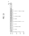
- FIG. 13 shows a CCE that can be the starting location of the UE-specific search space.
- the total number of CCEs constituting a logical CCE stream in a k-th subframe is N CCE,K .
- the CCEs are indexed from 0 to N CCE,K -1'.
- the number of available UE-specific search spaces on the CCE stream of the k-th subframe is ⁇ N CCE , k L ⁇ , where [x] is a floor function which gives a largest integer less than or equal to x. It can be seen that the number of available UE-specific search spaces is reduced. Therefore, a possibility that the search space specified to one UE overlaps with the search space specified to another UE can be reduced. In addition, an overhead can be reduced when a BS schedules a PDCCH on the CCE stream for each of a plurality of UEs.
- the CCE aggregation level is L, it is effective to limit the CCE that can be the starting location of the UE-specific search space on the CCE stream to a multiple of the CCE aggregation level L.
- a set of CCE indices that can be the starting location Z k (L) of the UE-specific search space in the k-th subframe can be expressed by Equation 2 below. Z k L ⁇ 0 , L , 2 ⁇ L , 3 ⁇ L , ... , L ⁇ ⁇ N CCE , k L ⁇ - 1
- Table 3 below shows an example of a search space.
- a size L of CCE aggregation level and the number M (L) of PDCCH candidates are for exemplary purposes only, and thus the present invention is not limited thereto.
- Table 3 Search space Number of PDCCH candidates M (L) Type Aggregation Level L [CCEs] Size of Search Space [in CCEs] UE- specific 1 6 2 12 6 4 8 2 8 16 2 Common 4 16 4 8 16 2
- the UE-specific search space supports a CCE aggregation level L, where L ⁇ 1,2,4,8 ⁇ .
- the common search space supports the CCE aggregation level L, where L ⁇ 4,8 ⁇ .
- the size of search space is determined according to the size of CCE aggregation level and the number of PDCCH candidates. That is, the size of search space is a multiple of the size of CCE aggregation level or a multiple of the number of PDCCH candidates.
- the starting location is a point where a first PDCCH candidate is located in the search space.
- the UE detects the PDCCH allocated to the UE by decoding PDCCH candidates in the unit of the CCE aggregation level from the starting location in the search space.
- a modulo operation is performed for cyclic search on the CCE stream.
- the starting location of the UE-specific search space may differ for each CCE aggregation level or each UE.
- the starting location of the common search space is the same for all UEs in a cell.
- a method of indexing CCEs will be described when a CCE that can be a starting location of a UE-specific search space on a CCE stream is limited to be a multiple of a CCE aggregation level L.
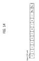
- FIG. 14 shows an example of a method of indexing CCEs on a CCE stream.
- the total number of CCEs constituting the CCE stream is N CCE .
- the CCEs are sequentially indexed from 0 to 'N CCE -1'. Irrespective of a CCE aggregation level, the CCEs are indexed in a basic CCE unit.
- FIG. 15 shows an example of a method of indexing CCEs when a CCE aggregation level is 2.
- the total number of CCEs constituting a CCE stream is N CCE .
- a first CCE of each aggregated CCE unit is indexed.
- the aggregated CCE units are sequentially indexed from 0 to 'N CCE /2-1'.
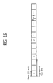
- FIG. 16 shows an example of a method of indexing CCEs when a CCE aggregation level is K.
- the total number of CCEs constituting a CCE stream is N CCE .
- a first CCE of each aggregated CCE unit is indexed.
- the aggregated CCE units are sequentially indexed from 0 to 'N CCE /K-1'.
- Equation 7 the CCE aggregation level L is multiplied in Equation 7.
- the CCE aggregation level L is multiplied in Equation 8.
- the UE can effectively monitors the PDCCH.
- the BS can effectively multiplex and transmit a plurality of PDCCHs carrying control information regarding a plurality of UEs. Therefore, the number of detection attempts depending on blind decoding for monitoring the PDCCH can be reduced. An overhead caused by blind decoding is reduced, and a time for finding the downlink control channel required by the UE is reduced. A battery consumption of the UE is reduced, and overall system performance can be improved.
- the present invention can be implemented with hardware, software, or combination thereof.
- the present invention can be implemented with one of an application specific integrated circuit (ASIC), a digital signal processor (DSP), a programmable logic device (PLD), a field programmable gate array (FPGA), a processor, a controller, a microprocessor, other electronic units, and combination thereof, which are designed to perform the aforementioned functions.
- ASIC application specific integrated circuit
- DSP digital signal processor
- PLD programmable logic device
- FPGA field programmable gate array
- the present invention can be implemented with a module for performing the aforementioned functions.
- Software is storable in a memory unit and executed by a processor.
- Various means widely known to those skilled in the art can be used as the memory unit or the processor.
Landscapes
- Engineering & Computer Science (AREA)
- Signal Processing (AREA)
- Computer Networks & Wireless Communication (AREA)
- Computer Security & Cryptography (AREA)
- Mobile Radio Communication Systems (AREA)
Priority Applications (1)
| Application Number | Priority Date | Filing Date | Title |
|---|---|---|---|
| PL09004042T PL2104294T3 (pl) | 2008-03-20 | 2009-03-20 | Monitorowanie kanału sterującego w systemie komunikacji bezprzewodowej |
Applications Claiming Priority (4)
| Application Number | Priority Date | Filing Date | Title |
|---|---|---|---|
| US3805608P | 2008-03-20 | 2008-03-20 | |
| US3841508P | 2008-03-21 | 2008-03-21 | |
| US3911208P | 2008-03-25 | 2008-03-25 | |
| KR1020080083131A KR100913473B1 (ko) | 2008-03-20 | 2008-08-26 | 무선 통신 시스템에서 pdcch 모니터링 방법 |
Publications (3)
| Publication Number | Publication Date |
|---|---|
| EP2104294A2 true EP2104294A2 (fr) | 2009-09-23 |
| EP2104294A3 EP2104294A3 (fr) | 2011-03-30 |
| EP2104294B1 EP2104294B1 (fr) | 2012-06-13 |
Family
ID=40792811
Family Applications (1)
| Application Number | Title | Priority Date | Filing Date |
|---|---|---|---|
| EP09004042A Active EP2104294B1 (fr) | 2008-03-20 | 2009-03-20 | Surveillance d'un canal de contrôle dans un système de communication sans fil |
Country Status (9)
| Country | Link |
|---|---|
| US (2) | US9525580B2 (fr) |
| EP (1) | EP2104294B1 (fr) |
| JP (1) | JP4995857B2 (fr) |
| KR (1) | KR100913473B1 (fr) |
| ES (1) | ES2388044T3 (fr) |
| HR (1) | HRP20120507T1 (fr) |
| PL (1) | PL2104294T3 (fr) |
| PT (1) | PT2104294E (fr) |
| WO (1) | WO2009116824A1 (fr) |
Cited By (21)
| Publication number | Priority date | Publication date | Assignee | Title |
|---|---|---|---|---|
| WO2011035495A1 (fr) * | 2009-09-28 | 2011-03-31 | 华为技术有限公司 | Procédé et dispositif de détection aveugle pour canal de commande de liaison descendante physique |
| EP2193616A4 (fr) * | 2007-09-28 | 2011-05-11 | Lg Electronics Inc | Système de communication sans fil de surveillance d'un canal de commande physique en liaison descendante |
| CN102186193A (zh) * | 2011-05-06 | 2011-09-14 | 中兴通讯股份有限公司 | 误检测判决方法及装置 |
| WO2011055992A3 (fr) * | 2009-11-05 | 2011-10-27 | Pantech Co.,Ltd. | Appareil et procédé d'envoi et de réception d'informations de commande dans un système de communication sans fil |
| CN102469048A (zh) * | 2010-11-18 | 2012-05-23 | 中兴通讯股份有限公司 | 一种确定下行控制信道搜索空间的方法及系统 |
| CN103069731A (zh) * | 2010-06-08 | 2013-04-24 | 韩国电子通信研究院 | 多载波无线通信系统中的收发方法及装置 |
| WO2013109501A1 (fr) | 2012-01-16 | 2013-07-25 | Research In Motion Limited | Conception de canal de commande de liaison descendante physique amélioré (e-pdcch) pour réduire un décodage aveugle |
| CN103391160A (zh) * | 2012-05-07 | 2013-11-13 | 开曼晨星半导体公司 | 控制频道解调解码方法及应用该控制频道解调解码方法的通信装置 |
| EP2667667A4 (fr) * | 2011-01-19 | 2014-03-26 | Huawei Tech Co Ltd | Procédé de traitement, procédé de communication, et dispositif |
| US8739013B2 (en) | 2007-09-28 | 2014-05-27 | Lg Electronics Inc. | Method for detecting control information in wireless communication system |
| EP2263338A4 (fr) * | 2008-08-13 | 2015-03-04 | Lg Electronics Inc | Procédé et dispositif d'attribution d'identifiants à un équipement utilisateur dans un système cellulaire |
| US9198181B2 (en) | 2012-03-19 | 2015-11-24 | Blackberry Limited | Enhanced common downlink control channels |
| US9215058B2 (en) | 2012-03-06 | 2015-12-15 | Blackberry Limited | Enhanced PHICH transmission for LTE-advanced |
| EP2503813A4 (fr) * | 2009-11-16 | 2016-03-16 | Zte Corp | Procédé et dispositif d'affectation de ressources d'élément de canal de commande |
| TWI551096B (zh) * | 2010-02-12 | 2016-09-21 | 富士通股份有限公司 | 無線通訊裝置、無線通訊系統及無線通訊方法 |
| US9485052B2 (en) | 2007-09-28 | 2016-11-01 | Lg Electronics Inc. | Method for detecting control information in wireless communication system |
| EP2557710A4 (fr) * | 2010-04-07 | 2017-07-26 | LG Electronics Inc. | Procédé et appareil de surveillance de canal pdcch dans un système de ligne de jonction de porteuse |
| EP3709749A1 (fr) * | 2007-10-29 | 2020-09-16 | Interdigital Patent Holdings, Inc. | Traitement des réponses des canaux d'accès aléatoire |
| EP3840494A4 (fr) * | 2018-08-17 | 2022-05-18 | KT Corporation | Procédé et dispositif de radiomessagerie dans une bande sans licence |
| US11533703B2 (en) | 2018-08-17 | 2022-12-20 | Kt Corporation | Paging method and device in unlicensed band |
| US12284634B2 (en) | 2011-10-13 | 2025-04-22 | Electronics And Telecommunications Research Institute | Method and apparatus of peer link setting, and method and apparatus of channel switching, in wireless mesh network |
Families Citing this family (82)
| Publication number | Priority date | Publication date | Assignee | Title |
|---|---|---|---|---|
| EP1901496B1 (fr) * | 2006-09-12 | 2010-09-01 | Panasonic Corporation | Adaptation de liaison dépendant de la signalisation de contrôle |
| KR101376233B1 (ko) * | 2007-10-02 | 2014-03-21 | 삼성전자주식회사 | 주파수 분할 다중 접속 방식의 시스템에서 제어 채널의자원 할당 장치 및 방법 |
| KR100943908B1 (ko) | 2008-02-19 | 2010-02-24 | 엘지전자 주식회사 | Pdcch를 통한 제어 정보 송수신 방법 |
| US9172509B2 (en) | 2008-04-11 | 2015-10-27 | Interdigital Patent Holdings, Inc. | Method for transmission time interval bundling in the uplink |
| CN101978721B (zh) * | 2008-04-24 | 2013-07-31 | 夏普株式会社 | 移动站装置、移动通信系统以及通信方法 |
| US8619684B2 (en) * | 2008-05-01 | 2013-12-31 | Qualcomm Incorporated | Method and apparatus for downlink data arrival |
| US9001745B2 (en) * | 2009-03-13 | 2015-04-07 | Blackberry Limited | HARQ process number management for downlink carrier |
| SG174384A1 (en) | 2009-03-16 | 2011-10-28 | Research In Motion Ltd | Harq process number management for downlink carrier aggregation |
| KR101789325B1 (ko) * | 2009-05-14 | 2017-10-24 | 엘지전자 주식회사 | 다중 반송파 시스템에서 제어채널을 모니터링하는 장치 및 방법 |
| EP2445289B1 (fr) * | 2009-06-16 | 2015-09-23 | Huawei Technologies Co., Ltd. | Procédé de mappage de canal de commande, procédé de détection de canal de commande et dispositif correspondant |
| CN102804867B (zh) | 2009-06-16 | 2016-07-27 | 夏普株式会社 | 移动站装置、基站装置以及无线通信方法 |
| CN101925109B (zh) * | 2009-06-16 | 2012-12-26 | 华为技术有限公司 | 一种控制信道映射的方法和装置 |
| US8340676B2 (en) * | 2009-06-25 | 2012-12-25 | Motorola Mobility Llc | Control and data signaling in heterogeneous wireless communication networks |
| US8503364B2 (en) * | 2009-07-14 | 2013-08-06 | Qualcomm Incorporated | Broadcast signaling L1 overload indication |
| US20110013574A1 (en) * | 2009-07-16 | 2011-01-20 | Chia-Chun Hsu | Method of Handling Unicast Transmission on Multimedia Broadcast Multicast Service Subframe and Related Communication Device |
| CN101969604B (zh) * | 2009-07-28 | 2015-08-12 | 中兴通讯股份有限公司 | 一种多媒体广播和组播业务通知消息的发送方法和装置 |
| CN101998577B (zh) * | 2009-08-14 | 2013-06-05 | 电信科学技术研究院 | 随机接入前导码的发送方法、系统及设备 |
| US9351293B2 (en) * | 2009-09-11 | 2016-05-24 | Qualcomm Incorporated | Multiple carrier indication and downlink control information interaction |
| US9763197B2 (en) * | 2009-10-05 | 2017-09-12 | Qualcomm Incorporated | Component carrier power control in multi-carrier wireless network |
| CN101702828B (zh) * | 2009-11-03 | 2013-01-02 | 中兴通讯股份有限公司 | 资源分配方法及系统、盲检测方法、基站、用户设备 |
| US9559829B2 (en) * | 2009-11-04 | 2017-01-31 | Telefonaktiebolaget Lm Ericsson (Publ) | Signaling for flexible carrier aggregation |
| JP5395641B2 (ja) * | 2009-11-30 | 2014-01-22 | シャープ株式会社 | 通信システム及び移動局装置及び基地局装置及び処理方法 |
| US9124406B2 (en) | 2009-12-29 | 2015-09-01 | Qualcomm Incorporated | Fallback operation for cross-carrier signaling in multi-carrier operation |
| JP5285629B2 (ja) * | 2010-01-11 | 2013-09-11 | 株式会社エヌ・ティ・ティ・ドコモ | 基地局装置、移動局装置及び制御情報送信方法 |
| CN102158808B (zh) * | 2010-02-11 | 2016-03-30 | 中兴通讯股份有限公司 | Mcch信息的接收方法及装置、用户设备 |
| CN102158807B (zh) * | 2010-02-11 | 2015-01-28 | 中兴通讯股份有限公司 | Mcch通知信息的监听方法及装置、用户设备 |
| JP4862086B2 (ja) | 2010-03-04 | 2012-01-25 | シャープ株式会社 | 無線通信システム、基地局装置、移動局装置、無線通信方法および集積回路 |
| EP2547017B1 (fr) * | 2010-03-11 | 2018-08-29 | LG Electronics Inc. | Procédé d'allocation de voie de signalisation et son appareil |
| US8989026B2 (en) * | 2010-03-18 | 2015-03-24 | Qualcomm Incorporated | User-specific search space design for multi-carrier operation |
| CA2793053C (fr) * | 2010-03-25 | 2016-08-16 | Sharp Kabushiki Kaisha | Procede de communication, dispositif formant station mobile, dispositif formant station de base et systeme de communication mobile |
| US8908714B2 (en) | 2010-03-31 | 2014-12-09 | Lg Electronics Inc. | Selective discontinuous reception method and related system and device |
| AU2014202400B2 (en) * | 2010-04-05 | 2016-05-19 | Ntt Docomo, Inc. | Base station apparatus and user terminal |
| EP2378703A1 (fr) | 2010-04-13 | 2011-10-19 | Panasonic Corporation | Cartographie d'informations de contrôle pour contrôler des éléments de canaux |
| WO2011160285A1 (fr) * | 2010-06-21 | 2011-12-29 | Huawei Technologies Co., Ltd. | Attribution et réception d'un canal de commande |
| WO2012011239A1 (fr) | 2010-07-21 | 2012-01-26 | パナソニック株式会社 | Dispositif de station de base, dispositif de terminal, procédé de transmission et procédé de réception |
| US9031025B2 (en) * | 2010-07-21 | 2015-05-12 | Panasonic Intellectual Property Corporation Of America | Base station, terminal, search space setting method and decoding method |
| CN102347919B (zh) * | 2010-08-05 | 2014-02-26 | 普天信息技术研究院有限公司 | 一种盲检测方法 |
| US8917586B2 (en) | 2010-10-01 | 2014-12-23 | Blackberry Limited | Orthogonal resource selection transmit diversity and resource assignment |
| US8717920B2 (en) * | 2010-10-08 | 2014-05-06 | Telefonaktiebolaget L M Ericsson (Publ) | Signalling mechanism for multi-tiered intra-band carrier aggregation |
| US9198094B2 (en) * | 2011-02-24 | 2015-11-24 | Lg Electronics Inc. | Method for setting search space for handover of relay node in wireless communication system, and device therefor |
| WO2012124981A2 (fr) | 2011-03-14 | 2012-09-20 | 엘지전자 주식회사 | Procédé et dispositif destinés à l'émission d'informations de commande dans un système de communication sans fil |
| US10638464B2 (en) | 2011-04-01 | 2020-04-28 | Futurewei Technologies, Inc. | System and method for transmission and reception of control channels in a communications system |
| ES2726304T3 (es) * | 2011-05-03 | 2019-10-03 | Ericsson Telefon Ab L M | Monitorización de canal de control basada en un área de búsqueda |
| CN102202324B (zh) * | 2011-05-19 | 2013-07-10 | 电信科学技术研究院 | 资源位置指示及信道盲检的方法、系统和装置 |
| US9544790B2 (en) | 2011-06-28 | 2017-01-10 | Lg Electronics Inc. | Method for monitoring downlink control information (DCI) and a user equipment using the same |
| EP2732593B1 (fr) * | 2011-07-12 | 2018-09-05 | LG Electronics Inc. | Procédé de transmission ou de réception de pdcch et équipement utilisateur ou station de base pour le procédé |
| US8908492B2 (en) | 2011-08-11 | 2014-12-09 | Blackberry Limited | Orthogonal resource selection transmit diversity and resource assignment |
| US20130039290A1 (en) * | 2011-08-11 | 2013-02-14 | Research In Motion Korea | Method and System for Uplink Control Channel Transmit Diversity Using Multiple Downlink Control Channel Based Resource Allocation |
| TW201322813A (zh) | 2011-08-11 | 2013-06-01 | Research In Motion Ltd | 正交資源選擇傳輸分集及資源指派 |
| US8891353B2 (en) | 2011-08-11 | 2014-11-18 | Blackberry Limited | Orthogonal resource selection transmit diversity and resource assignment |
| CN102355340B (zh) * | 2011-08-12 | 2017-02-08 | 中兴通讯股份有限公司 | 下行控制信息发送、接收方法及装置 |
| US9402264B2 (en) * | 2011-09-30 | 2016-07-26 | Intel Corporation | Methods to transport internet traffic over multiple wireless networks simultaneously |
| US9497737B2 (en) | 2011-10-31 | 2016-11-15 | Lg Electronics Inc. | Method and apparatus for searching for control channel in multi-node system |
| US10079658B2 (en) * | 2011-11-04 | 2018-09-18 | Qualcomm Incorporated | Search space design for e-PDCCH in wireless communication networks |
| KR20130054180A (ko) | 2011-11-14 | 2013-05-24 | 삼성전자주식회사 | 무선 통신 시스템에서 제어 채널 전송을 위한 레퍼런스 시그널링 리소스 할당 방법 |
| JP6219846B2 (ja) | 2012-01-18 | 2017-10-25 | エルジー エレクトロニクス インコーポレイティド | 無線通信システムにおいて改善された制御チャネルベースの動作方法及び装置 |
| CN104067640B (zh) * | 2012-01-30 | 2019-03-19 | 华为技术有限公司 | 用于通信系统中的公共控制信道的系统和方法 |
| EP2639989A1 (fr) * | 2012-03-16 | 2013-09-18 | Panasonic Corporation | Espace de recherche pour informations de contrôle ePDCCH dans un système de communication mobile OFDM |
| WO2014038904A1 (fr) * | 2012-09-07 | 2014-03-13 | Samsung Electronics Co., Ltd. | Multiplexage de groupes d'éléments de ressources servant aux éléments de canaux de commande des canaux de commande |
| BR112015006596A2 (pt) | 2012-09-27 | 2017-07-04 | Alcatel Lucent | método para determinar recursos de canais físicos de controle de enlace direto |
| JP6082481B2 (ja) * | 2013-03-18 | 2017-02-15 | エルジー エレクトロニクス インコーポレイティド | 無線通信システムにおいて基地局が端末に制御チャネルを送信する方法及びそのための装置 |
| US11064329B2 (en) * | 2013-04-17 | 2021-07-13 | Qualcomm Incorporated | Control-less operation for coverage limited machine-type-communications |
| US9398579B2 (en) | 2013-05-03 | 2016-07-19 | Qualcomm Incorporated | Systems and methods for downlink frequency domain multiplexing transmissions |
| WO2015057028A1 (fr) * | 2013-10-17 | 2015-04-23 | Lg Electronics Inc. | Procédé et appareil de communication sans fil |
| CN104753634B (zh) * | 2013-12-31 | 2017-10-24 | 展讯通信(上海)有限公司 | Dci的检测方法和装置 |
| EP3247061B1 (fr) * | 2015-01-12 | 2023-03-01 | LG Electronics Inc. | Procédé de fonctionnement d'un équipement utilisateur dans un système de communication sans fil, et dispositif associé |
| WO2016169047A1 (fr) * | 2015-04-24 | 2016-10-27 | Telefonaktiebolaget Lm Ericsson (Publ) | Procédé et nœud de réseau pour attribution de ressources pdcch |
| US11277235B2 (en) * | 2015-11-23 | 2022-03-15 | Qualcomm Incorporated | Techniques for multiplexing or cascading control information and data within a transmission time interval |
| DE102015121994B4 (de) * | 2015-12-16 | 2017-09-14 | Intel IP Corporation | Verfahren zur Energieverwaltung und Energieverwaltungscontroller für einen Funkempfänger |
| WO2017132955A1 (fr) | 2016-02-04 | 2017-08-10 | 华为技术有限公司 | Procédé de transmission d'informations de commande, station de base, et terminal |
| KR20180068677A (ko) * | 2016-12-14 | 2018-06-22 | 삼성전자주식회사 | 무선 통신 시스템에서 하향링크 제어채널의 송수신 방법 및 장치 |
| US10925048B2 (en) * | 2017-03-30 | 2021-02-16 | Qualcomm Incorporated | Control resource set for single-carrier waveform |
| WO2019028830A1 (fr) * | 2017-08-11 | 2019-02-14 | Zte Corporation | Détection aveugle de canal de commande candidat |
| EP3753152A1 (fr) * | 2018-02-15 | 2020-12-23 | FRAUNHOFER-GESELLSCHAFT zur Förderung der angewandten Forschung e.V. | Réception améliorée de message de commande au niveau d'un récepteur |
| US10880878B2 (en) * | 2018-02-16 | 2020-12-29 | Qualcomm Incorporated | Physical downlink control channel hash function update |
| CN110972515B (zh) | 2018-07-31 | 2022-06-14 | Lg电子株式会社 | 在无线通信系统中监测终端的控制信号的方法及其终端 |
| US11470596B2 (en) | 2019-07-18 | 2022-10-11 | Samsung Electronics Co., Ltd. | Determination of start time of PDCCH monitoring occasion |
| EP4226708A4 (fr) * | 2020-10-05 | 2024-10-16 | Apple Inc. | Opérations de réseau pour réduire la surveillance de pdcch |
| CN116326049B (zh) | 2020-10-05 | 2025-09-12 | 苹果公司 | 用户装备的降低的pdcch监测 |
| CN114362886B (zh) * | 2022-01-11 | 2024-03-01 | 赛特斯信息科技股份有限公司 | 基于聚合等级预估的终端pdcch盲检方法 |
| KR102815017B1 (ko) | 2022-04-28 | 2025-05-30 | 엘지전자 주식회사 | 하향링크 제어 채널을 송수신하는 방법 및 이를 위한 장치 |
| KR20230153234A (ko) | 2022-04-28 | 2023-11-06 | 엘지전자 주식회사 | 하향링크 제어 채널을 송수신하는 방법 및 이를 위한 장치 |
Family Cites Families (13)
| Publication number | Priority date | Publication date | Assignee | Title |
|---|---|---|---|---|
| US20030016702A1 (en) * | 2001-03-30 | 2003-01-23 | Bender Paul E. | Method and system for maximizing standby time in monitoring a control channel |
| US20060067263A1 (en) * | 2004-09-30 | 2006-03-30 | Qinghua Li | Techniques to manage multiple receivers |
| KR20060077854A (ko) * | 2004-12-31 | 2006-07-05 | 삼성전자주식회사 | 이동통신 시스템의 파일럿 채널 탐색 속도 제어 방법과이를 이용한 파일럿 채널 탐색기 |
| KR20090029620A (ko) * | 2007-09-18 | 2009-03-23 | 엘지전자 주식회사 | 무선통신 시스템에서 시스템 정보 갱신 방법 |
| KR101448309B1 (ko) * | 2007-09-28 | 2014-10-08 | 엘지전자 주식회사 | 무선통신 시스템에서 하향링크 제어채널 모니터링 방법 |
| WO2009041785A2 (fr) | 2007-09-28 | 2009-04-02 | Lg Electronics Inc. | Procédé de détection d'informations de commande dans un système de communication sans fil |
| WO2009049267A1 (fr) * | 2007-10-12 | 2009-04-16 | Beceem Communications Inc. | Procédé d'estimation de plusieurs canaux par un récepteur |
| MX2010004489A (es) * | 2007-10-29 | 2010-05-05 | Panasonic Corp | Aparato de estacion de base de comunicacion inalambrica, aparato de estacion movil de comunicacion inalambrica y metodo de distribucion de canal de control. |
| US8238475B2 (en) * | 2007-10-30 | 2012-08-07 | Qualcomm Incorporated | Methods and systems for PDCCH blind decoding in mobile communications |
| US8687745B2 (en) | 2007-12-13 | 2014-04-01 | Telefonaktiebolaget Lm Ericsson (Publ) | Method and apparatus for blind decoding |
| KR101459147B1 (ko) * | 2008-02-04 | 2014-11-10 | 엘지전자 주식회사 | 무선통신 시스템에서 전송 파워 제어 명령 전송 방법 |
| KR100943908B1 (ko) | 2008-02-19 | 2010-02-24 | 엘지전자 주식회사 | Pdcch를 통한 제어 정보 송수신 방법 |
| JP2009218813A (ja) * | 2008-03-10 | 2009-09-24 | Mitsubishi Electric Corp | 通信システムおよび基地局 |
-
2008
- 2008-08-26 KR KR1020080083131A patent/KR100913473B1/ko active Active
-
2009
- 2009-03-19 JP JP2009069142A patent/JP4995857B2/ja active Active
- 2009-03-19 US US12/933,378 patent/US9525580B2/en active Active
- 2009-03-19 US US12/407,538 patent/US7733827B2/en active Active
- 2009-03-19 WO PCT/KR2009/001418 patent/WO2009116824A1/fr not_active Ceased
- 2009-03-20 PL PL09004042T patent/PL2104294T3/pl unknown
- 2009-03-20 PT PT09004042T patent/PT2104294E/pt unknown
- 2009-03-20 EP EP09004042A patent/EP2104294B1/fr active Active
- 2009-03-20 ES ES09004042T patent/ES2388044T3/es active Active
-
2012
- 2012-06-18 HR HRP20120507AT patent/HRP20120507T1/hr unknown
Non-Patent Citations (4)
| Title |
|---|
| ERICSSON: "PDCCH blind decoding - Outcome of offline discussions", 20080211, no. R1-081101, 11 February 2008 (2008-02-11), pages 1-7, XP002542364, DOI: DOI:HTTP://FTP.3GPP.ORG/TSG_RAN/WG1_RL1/TS GR1_52/DOCS/?C=N;O=D [retrieved on 2009-08-21] * |
| MITSUBISHI ELECTRIC: "Blind detection complexity reduction with UE specific PDCCH scrambling", 3GPP DRAFT; R1-080405, 3RD GENERATION PARTNERSHIP PROJECT (3GPP), MOBILE COMPETENCE CENTRE ; 650, ROUTE DES LUCIOLES ; F-06921 SOPHIA-ANTIPOLIS CEDEX ; FRANCE, vol. RAN WG1, no. Sevilla, Spain; 20080109, 9 January 2008 (2008-01-09), XP050108924, [retrieved on 2008-01-09] * |
| QUALCOMM EUROPE: "PDCCH Blind Decodes", 3GPP DRAFT; R1-080646, 3RD GENERATION PARTNERSHIP PROJECT (3GPP), MOBILE COMPETENCE CENTRE ; 650, ROUTE DES LUCIOLES ; F-06921 SOPHIA-ANTIPOLIS CEDEX ; FRANCE, vol. RAN WG1, no. Sorrento, Italy; 20080206, 6 February 2008 (2008-02-06), XP050109147, [retrieved on 2008-02-06] * |
| SAMSUNG: "Configuration of PDCCH Monitoring Set", 3GPP DRAFT; R1-080028 PDCCH RESTRICTION, 3RD GENERATION PARTNERSHIP PROJECT (3GPP), MOBILE COMPETENCE CENTRE ; 650, ROUTE DES LUCIOLES ; F-06921 SOPHIA-ANTIPOLIS CEDEX ; FRANCE, vol. RAN WG1, no. Sevilla, Spain; 20080108, 8 January 2008 (2008-01-08), XP050108571, [retrieved on 2008-01-08] * |
Cited By (38)
| Publication number | Priority date | Publication date | Assignee | Title |
|---|---|---|---|---|
| US9560600B2 (en) | 2007-09-28 | 2017-01-31 | Lg Electronics Inc. | Method for detecting control information in wireless communication system |
| US9485052B2 (en) | 2007-09-28 | 2016-11-01 | Lg Electronics Inc. | Method for detecting control information in wireless communication system |
| US11057840B2 (en) | 2007-09-28 | 2021-07-06 | Lg Electronics Inc. | Method for detecting control information in wireless communication system |
| US8739013B2 (en) | 2007-09-28 | 2014-05-27 | Lg Electronics Inc. | Method for detecting control information in wireless communication system |
| US10555264B2 (en) | 2007-09-28 | 2020-02-04 | Lg Electronics Inc. | Method for detecting control information in wireless communication system |
| US8401542B2 (en) | 2007-09-28 | 2013-03-19 | Lg Electronics Inc. | Wireless communication system for monitoring physical downlink control channel |
| EP2193616A4 (fr) * | 2007-09-28 | 2011-05-11 | Lg Electronics Inc | Système de communication sans fil de surveillance d'un canal de commande physique en liaison descendante |
| EP3709749A1 (fr) * | 2007-10-29 | 2020-09-16 | Interdigital Patent Holdings, Inc. | Traitement des réponses des canaux d'accès aléatoire |
| EP2263338A4 (fr) * | 2008-08-13 | 2015-03-04 | Lg Electronics Inc | Procédé et dispositif d'attribution d'identifiants à un équipement utilisateur dans un système cellulaire |
| WO2011035495A1 (fr) * | 2009-09-28 | 2011-03-31 | 华为技术有限公司 | Procédé et dispositif de détection aveugle pour canal de commande de liaison descendante physique |
| WO2011055992A3 (fr) * | 2009-11-05 | 2011-10-27 | Pantech Co.,Ltd. | Appareil et procédé d'envoi et de réception d'informations de commande dans un système de communication sans fil |
| EP2503813A4 (fr) * | 2009-11-16 | 2016-03-16 | Zte Corp | Procédé et dispositif d'affectation de ressources d'élément de canal de commande |
| TWI551096B (zh) * | 2010-02-12 | 2016-09-21 | 富士通股份有限公司 | 無線通訊裝置、無線通訊系統及無線通訊方法 |
| EP2557710A4 (fr) * | 2010-04-07 | 2017-07-26 | LG Electronics Inc. | Procédé et appareil de surveillance de canal pdcch dans un système de ligne de jonction de porteuse |
| US9918335B2 (en) | 2010-04-07 | 2018-03-13 | Lg Electronics Inc. | PDCCH monitoring method and apparatus in a carrier junction system |
| CN103069731A (zh) * | 2010-06-08 | 2013-04-24 | 韩国电子通信研究院 | 多载波无线通信系统中的收发方法及装置 |
| CN103069731B (zh) * | 2010-06-08 | 2016-01-20 | 韩国电子通信研究院 | 多载波无线通信系统中的收发方法及装置 |
| US11743905B2 (en) | 2010-06-08 | 2023-08-29 | Electronics And Telecommunications Research Institute | Method and apparatus for transmission and reception in multi-carrier wireless communication systems |
| US10757694B2 (en) | 2010-06-08 | 2020-08-25 | Electronics And Telecommunications Research Institute | Method and apparatus for transmission and reception in multi-carrier wireless communication systems |
| WO2012065533A1 (fr) * | 2010-11-18 | 2012-05-24 | 中兴通讯股份有限公司 | Procédé et système permettant de déterminer un espace de recherche de canal de contrôle de liaison descendante physique de relais |
| CN102469048B (zh) * | 2010-11-18 | 2015-04-01 | 中兴通讯股份有限公司 | 一种确定下行控制信道搜索空间的方法及系统 |
| CN102469048A (zh) * | 2010-11-18 | 2012-05-23 | 中兴通讯股份有限公司 | 一种确定下行控制信道搜索空间的方法及系统 |
| EP2667667A4 (fr) * | 2011-01-19 | 2014-03-26 | Huawei Tech Co Ltd | Procédé de traitement, procédé de communication, et dispositif |
| CN102186193A (zh) * | 2011-05-06 | 2011-09-14 | 中兴通讯股份有限公司 | 误检测判决方法及装置 |
| US12284634B2 (en) | 2011-10-13 | 2025-04-22 | Electronics And Telecommunications Research Institute | Method and apparatus of peer link setting, and method and apparatus of channel switching, in wireless mesh network |
| EP2805438A4 (fr) * | 2012-01-16 | 2015-04-22 | Blackberry Ltd | Conception de canal de commande de liaison descendante physique amélioré (e-pdcch) pour réduire un décodage aveugle |
| EP3726770A1 (fr) * | 2012-01-16 | 2020-10-21 | BlackBerry Limited | Conception de canal de commande de liaison descendante physique amélioré (e-pdcch) pour réduire un décodage aveugle |
| WO2013109501A1 (fr) | 2012-01-16 | 2013-07-25 | Research In Motion Limited | Conception de canal de commande de liaison descendante physique amélioré (e-pdcch) pour réduire un décodage aveugle |
| EP4686120A3 (fr) * | 2012-01-16 | 2026-04-01 | Malikie Innovations Limited | Conception de canal e-pdcch pour réduire le décodage aveugle |
| US9998268B2 (en) | 2012-03-06 | 2018-06-12 | Blackberry Limited | Enhanced PHICH transmission for LTE-advanced |
| US9215058B2 (en) | 2012-03-06 | 2015-12-15 | Blackberry Limited | Enhanced PHICH transmission for LTE-advanced |
| US10063351B2 (en) | 2012-03-19 | 2018-08-28 | Blackberry Limited | Enhanced common downlink control channels |
| US9198181B2 (en) | 2012-03-19 | 2015-11-24 | Blackberry Limited | Enhanced common downlink control channels |
| CN103391160B (zh) * | 2012-05-07 | 2016-08-24 | 开曼晨星半导体公司 | 控制频道解调解码方法及应用该控制频道解调解码方法的通信装置 |
| EP2663001A1 (fr) * | 2012-05-07 | 2013-11-13 | MStar Semiconductor, Inc | Appareil de réception et démodulation de symboles OFDM et procédé de démodulation |
| CN103391160A (zh) * | 2012-05-07 | 2013-11-13 | 开曼晨星半导体公司 | 控制频道解调解码方法及应用该控制频道解调解码方法的通信装置 |
| EP3840494A4 (fr) * | 2018-08-17 | 2022-05-18 | KT Corporation | Procédé et dispositif de radiomessagerie dans une bande sans licence |
| US11533703B2 (en) | 2018-08-17 | 2022-12-20 | Kt Corporation | Paging method and device in unlicensed band |
Also Published As
| Publication number | Publication date |
|---|---|
| US20110021228A1 (en) | 2011-01-27 |
| US9525580B2 (en) | 2016-12-20 |
| PL2104294T3 (pl) | 2012-11-30 |
| JP4995857B2 (ja) | 2012-08-08 |
| PT2104294E (pt) | 2012-09-12 |
| EP2104294B1 (fr) | 2012-06-13 |
| KR100913473B1 (ko) | 2009-08-25 |
| JP2009232463A (ja) | 2009-10-08 |
| US7733827B2 (en) | 2010-06-08 |
| US20090238091A1 (en) | 2009-09-24 |
| WO2009116824A1 (fr) | 2009-09-24 |
| HRP20120507T1 (hr) | 2012-07-31 |
| ES2388044T3 (es) | 2012-10-08 |
| EP2104294A3 (fr) | 2011-03-30 |
Similar Documents
| Publication | Publication Date | Title |
|---|---|---|
| US7733827B2 (en) | Monitoring control channel in wireless communication system | |
| US8400939B2 (en) | Method for monitoring control channel in wireless communication system | |
| JP5048841B2 (ja) | 物理的ダウンリンク制御チャネルのモニタリングのための無線通信システム | |
| KR101485294B1 (ko) | 무선통신 시스템에서 전송 파워 제어 명령 전송 방법 | |
| KR102384606B1 (ko) | Mtc(machine type communication) 디바이스의 커버리지를 향상시키는 방법 및 장치 | |
| JP5048839B2 (ja) | 無線通信システムにおける制御情報検出方法 | |
| US20120044821A1 (en) | Control channel monitoring apparatus in multi-carrier system and method thereof | |
| KR20090083269A (ko) | 무선 통신 시스템에서 pdcch 검색 방법 | |
| KR101556417B1 (ko) | 무선 통신 시스템에서 시스템 정보 변경 여부 확인 방법 | |
| KR101514068B1 (ko) | 제어 정보 전송 방법 | |
| HK40052173A (en) | Method and apparatuses for transmitting feedback | |
| HK1240737A1 (en) | Method and apparatus for enhancing coverage of machine type communication (mtc) devices |
Legal Events
| Date | Code | Title | Description |
|---|---|---|---|
| PUAI | Public reference made under article 153(3) epc to a published international application that has entered the european phase |
Free format text: ORIGINAL CODE: 0009012 |
|
| AK | Designated contracting states |
Kind code of ref document: A2 Designated state(s): AT BE BG CH CY CZ DE DK EE ES FI FR GB GR HR HU IE IS IT LI LT LU LV MC MK MT NL NO PL PT RO SE SI SK TR |
|
| AX | Request for extension of the european patent |
Extension state: AL BA RS |
|
| PUAL | Search report despatched |
Free format text: ORIGINAL CODE: 0009013 |
|
| AK | Designated contracting states |
Kind code of ref document: A3 Designated state(s): AT BE BG CH CY CZ DE DK EE ES FI FR GB GR HR HU IE IS IT LI LT LU LV MC MK MT NL NO PL PT RO SE SI SK TR |
|
| AX | Request for extension of the european patent |
Extension state: AL BA RS |
|
| RIC1 | Information provided on ipc code assigned before grant |
Ipc: H04L 27/26 20060101AFI20090702BHEP Ipc: H04L 5/00 20060101ALI20110218BHEP |
|
| 17P | Request for examination filed |
Effective date: 20110627 |
|
| AKX | Designation fees paid |
Designated state(s): AT BE BG CH CY CZ DE DK EE ES FI FR GB GR HR HU IE IS IT LI LT LU LV MC MK MT NL NO PL PT RO SE SI SK TR |
|
| GRAP | Despatch of communication of intention to grant a patent |
Free format text: ORIGINAL CODE: EPIDOSNIGR1 |
|
| GRAS | Grant fee paid |
Free format text: ORIGINAL CODE: EPIDOSNIGR3 |
|
| GRAA | (expected) grant |
Free format text: ORIGINAL CODE: 0009210 |
|
| AK | Designated contracting states |
Kind code of ref document: B1 Designated state(s): AT BE BG CH CY CZ DE DK EE ES FI FR GB GR HR HU IE IS IT LI LT LU LV MC MK MT NL NO PL PT RO SE SI SK TR |
|
| REG | Reference to a national code |
Ref country code: GB Ref legal event code: FG4D |
|
| REG | Reference to a national code |
Ref country code: CH Ref legal event code: EP Ref country code: AT Ref legal event code: REF Ref document number: 562421 Country of ref document: AT Kind code of ref document: T Effective date: 20120615 |
|
| REG | Reference to a national code |
Ref country code: HR Ref legal event code: TUEP Ref document number: P20120507 Country of ref document: HR |
|
| REG | Reference to a national code |
Ref country code: IE Ref legal event code: FG4D |
|
| REG | Reference to a national code |
Ref country code: HR Ref legal event code: T1PR Ref document number: P20120507 Country of ref document: HR |
|
| REG | Reference to a national code |
Ref country code: NL Ref legal event code: T3 |
|
| REG | Reference to a national code |
Ref country code: RO Ref legal event code: EPE |
|
| REG | Reference to a national code |
Ref country code: DE Ref legal event code: R096 Ref document number: 602009007523 Country of ref document: DE Effective date: 20120816 |
|
| REG | Reference to a national code |
Ref country code: PT Ref legal event code: SC4A Free format text: AVAILABILITY OF NATIONAL TRANSLATION Effective date: 20120905 |
|
| REG | Reference to a national code |
Ref country code: SE Ref legal event code: TRGR |
|
| REG | Reference to a national code |
Ref country code: ES Ref legal event code: FG2A Ref document number: 2388044 Country of ref document: ES Kind code of ref document: T3 Effective date: 20121008 |
|
| PG25 | Lapsed in a contracting state [announced via postgrant information from national office to epo] |
Ref country code: LT Free format text: LAPSE BECAUSE OF FAILURE TO SUBMIT A TRANSLATION OF THE DESCRIPTION OR TO PAY THE FEE WITHIN THE PRESCRIBED TIME-LIMIT Effective date: 20120613 Ref country code: NO Free format text: LAPSE BECAUSE OF FAILURE TO SUBMIT A TRANSLATION OF THE DESCRIPTION OR TO PAY THE FEE WITHIN THE PRESCRIBED TIME-LIMIT Effective date: 20120913 Ref country code: CY Free format text: LAPSE BECAUSE OF FAILURE TO SUBMIT A TRANSLATION OF THE DESCRIPTION OR TO PAY THE FEE WITHIN THE PRESCRIBED TIME-LIMIT Effective date: 20120613 |
|
| REG | Reference to a national code |
Ref country code: LT Ref legal event code: MG4D Effective date: 20120613 |
|
| PG25 | Lapsed in a contracting state [announced via postgrant information from national office to epo] |
Ref country code: SI Free format text: LAPSE BECAUSE OF FAILURE TO SUBMIT A TRANSLATION OF THE DESCRIPTION OR TO PAY THE FEE WITHIN THE PRESCRIBED TIME-LIMIT Effective date: 20120613 Ref country code: LV Free format text: LAPSE BECAUSE OF FAILURE TO SUBMIT A TRANSLATION OF THE DESCRIPTION OR TO PAY THE FEE WITHIN THE PRESCRIBED TIME-LIMIT Effective date: 20120613 Ref country code: GR Free format text: LAPSE BECAUSE OF FAILURE TO SUBMIT A TRANSLATION OF THE DESCRIPTION OR TO PAY THE FEE WITHIN THE PRESCRIBED TIME-LIMIT Effective date: 20120914 |
|
| REG | Reference to a national code |
Ref country code: PL Ref legal event code: T3 |
|
| PG25 | Lapsed in a contracting state [announced via postgrant information from national office to epo] |
Ref country code: SK Free format text: LAPSE BECAUSE OF FAILURE TO SUBMIT A TRANSLATION OF THE DESCRIPTION OR TO PAY THE FEE WITHIN THE PRESCRIBED TIME-LIMIT Effective date: 20120613 Ref country code: CZ Free format text: LAPSE BECAUSE OF FAILURE TO SUBMIT A TRANSLATION OF THE DESCRIPTION OR TO PAY THE FEE WITHIN THE PRESCRIBED TIME-LIMIT Effective date: 20120613 Ref country code: EE Free format text: LAPSE BECAUSE OF FAILURE TO SUBMIT A TRANSLATION OF THE DESCRIPTION OR TO PAY THE FEE WITHIN THE PRESCRIBED TIME-LIMIT Effective date: 20120613 Ref country code: BE Free format text: LAPSE BECAUSE OF FAILURE TO SUBMIT A TRANSLATION OF THE DESCRIPTION OR TO PAY THE FEE WITHIN THE PRESCRIBED TIME-LIMIT Effective date: 20120613 Ref country code: IS Free format text: LAPSE BECAUSE OF FAILURE TO SUBMIT A TRANSLATION OF THE DESCRIPTION OR TO PAY THE FEE WITHIN THE PRESCRIBED TIME-LIMIT Effective date: 20121013 |
|
| PLBE | No opposition filed within time limit |
Free format text: ORIGINAL CODE: 0009261 |
|
| STAA | Information on the status of an ep patent application or granted ep patent |
Free format text: STATUS: NO OPPOSITION FILED WITHIN TIME LIMIT |
|
| PG25 | Lapsed in a contracting state [announced via postgrant information from national office to epo] |
Ref country code: DK Free format text: LAPSE BECAUSE OF FAILURE TO SUBMIT A TRANSLATION OF THE DESCRIPTION OR TO PAY THE FEE WITHIN THE PRESCRIBED TIME-LIMIT Effective date: 20120613 |
|
| 26N | No opposition filed |
Effective date: 20130314 |
|
| REG | Reference to a national code |
Ref country code: HU Ref legal event code: AG4A Ref document number: E015418 Country of ref document: HU |
|
| REG | Reference to a national code |
Ref country code: DE Ref legal event code: R097 Ref document number: 602009007523 Country of ref document: DE Effective date: 20130314 |
|
| PG25 | Lapsed in a contracting state [announced via postgrant information from national office to epo] |
Ref country code: BG Free format text: LAPSE BECAUSE OF FAILURE TO SUBMIT A TRANSLATION OF THE DESCRIPTION OR TO PAY THE FEE WITHIN THE PRESCRIBED TIME-LIMIT Effective date: 20120913 |
|
| PG25 | Lapsed in a contracting state [announced via postgrant information from national office to epo] |
Ref country code: MC Free format text: LAPSE BECAUSE OF NON-PAYMENT OF DUE FEES Effective date: 20130331 |
|
| REG | Reference to a national code |
Ref country code: CH Ref legal event code: PL |
|
| REG | Reference to a national code |
Ref country code: IE Ref legal event code: MM4A |
|
| PG25 | Lapsed in a contracting state [announced via postgrant information from national office to epo] |
Ref country code: IE Free format text: LAPSE BECAUSE OF NON-PAYMENT OF DUE FEES Effective date: 20130320 Ref country code: CH Free format text: LAPSE BECAUSE OF NON-PAYMENT OF DUE FEES Effective date: 20130331 Ref country code: LI Free format text: LAPSE BECAUSE OF NON-PAYMENT OF DUE FEES Effective date: 20130331 |
|
| PG25 | Lapsed in a contracting state [announced via postgrant information from national office to epo] |
Ref country code: MT Free format text: LAPSE BECAUSE OF FAILURE TO SUBMIT A TRANSLATION OF THE DESCRIPTION OR TO PAY THE FEE WITHIN THE PRESCRIBED TIME-LIMIT Effective date: 20120613 |
|
| PG25 | Lapsed in a contracting state [announced via postgrant information from national office to epo] |
Ref country code: MK Free format text: LAPSE BECAUSE OF FAILURE TO SUBMIT A TRANSLATION OF THE DESCRIPTION OR TO PAY THE FEE WITHIN THE PRESCRIBED TIME-LIMIT Effective date: 20120613 Ref country code: LU Free format text: LAPSE BECAUSE OF NON-PAYMENT OF DUE FEES Effective date: 20130320 |
|
| REG | Reference to a national code |
Ref country code: FR Ref legal event code: PLFP Year of fee payment: 8 |
|
| REG | Reference to a national code |
Ref country code: FR Ref legal event code: PLFP Year of fee payment: 9 |
|
| REG | Reference to a national code |
Ref country code: FR Ref legal event code: PLFP Year of fee payment: 10 |
|
| REG | Reference to a national code |
Ref country code: HR Ref legal event code: ODRP Ref document number: P20120507 Country of ref document: HR Payment date: 20190211 Year of fee payment: 11 |
|
| REG | Reference to a national code |
Ref country code: HR Ref legal event code: ODRP Ref document number: P20120507 Country of ref document: HR Payment date: 20200212 Year of fee payment: 12 |
|
| REG | Reference to a national code |
Ref country code: HR Ref legal event code: ODRP Ref document number: P20120507 Country of ref document: HR Payment date: 20210209 Year of fee payment: 13 |
|
| REG | Reference to a national code |
Ref country code: HR Ref legal event code: ODRP Ref document number: P20120507 Country of ref document: HR Payment date: 20220209 Year of fee payment: 14 |
|
| REG | Reference to a national code |
Ref country code: HR Ref legal event code: ODRP Ref document number: P20120507 Country of ref document: HR Payment date: 20230208 Year of fee payment: 15 |
|
| P01 | Opt-out of the competence of the unified patent court (upc) registered |
Effective date: 20230610 |
|
| REG | Reference to a national code |
Ref country code: HR Ref legal event code: ODRP Ref document number: P20120507 Country of ref document: HR Payment date: 20240206 Year of fee payment: 16 |
|
| REG | Reference to a national code |
Ref country code: HR Ref legal event code: ODRP Ref document number: P20120507 Country of ref document: HR Payment date: 20250210 Year of fee payment: 17 |
|
| PGFP | Annual fee paid to national office [announced via postgrant information from national office to epo] |
Ref country code: ES Payment date: 20250408 Year of fee payment: 17 |
|
| PGFP | Annual fee paid to national office [announced via postgrant information from national office to epo] |
Ref country code: NL Payment date: 20260206 Year of fee payment: 18 |
|
| REG | Reference to a national code |
Ref country code: HR Ref legal event code: ODRP Ref document number: P20120507 Country of ref document: HR Payment date: 20260205 Year of fee payment: 18 |
|
| PGFP | Annual fee paid to national office [announced via postgrant information from national office to epo] |
Ref country code: SE Payment date: 20260206 Year of fee payment: 18 |
|
| PGFP | Annual fee paid to national office [announced via postgrant information from national office to epo] |
Ref country code: GB Payment date: 20260209 Year of fee payment: 18 |
|
| PGFP | Annual fee paid to national office [announced via postgrant information from national office to epo] |
Ref country code: DE Payment date: 20260205 Year of fee payment: 18 |
|
| PGFP | Annual fee paid to national office [announced via postgrant information from national office to epo] |
Ref country code: HR Payment date: 20260205 Year of fee payment: 18 Ref country code: AT Payment date: 20260205 Year of fee payment: 18 |
|
| PGFP | Annual fee paid to national office [announced via postgrant information from national office to epo] |
Ref country code: RO Payment date: 20260310 Year of fee payment: 18 Ref country code: FI Payment date: 20260220 Year of fee payment: 18 Ref country code: IT Payment date: 20260206 Year of fee payment: 18 |
|
| PGFP | Annual fee paid to national office [announced via postgrant information from national office to epo] |
Ref country code: HU Payment date: 20260227 Year of fee payment: 18 |
|
| PGFP | Annual fee paid to national office [announced via postgrant information from national office to epo] |
Ref country code: FR Payment date: 20260209 Year of fee payment: 18 |
|
| PGFP | Annual fee paid to national office [announced via postgrant information from national office to epo] |
Ref country code: TR Payment date: 20260206 Year of fee payment: 18 |
|
| PGFP | Annual fee paid to national office [announced via postgrant information from national office to epo] |
Ref country code: PT Payment date: 20260206 Year of fee payment: 18 |
|
| PGFP | Annual fee paid to national office [announced via postgrant information from national office to epo] |
Ref country code: PL Payment date: 20260204 Year of fee payment: 18 |