EP2104321A1 - Zweiachsige Scharniervorrichtung und tragbares Endgerät - Google Patents
Zweiachsige Scharniervorrichtung und tragbares Endgerät Download PDFInfo
- Publication number
- EP2104321A1 EP2104321A1 EP09250370A EP09250370A EP2104321A1 EP 2104321 A1 EP2104321 A1 EP 2104321A1 EP 09250370 A EP09250370 A EP 09250370A EP 09250370 A EP09250370 A EP 09250370A EP 2104321 A1 EP2104321 A1 EP 2104321A1
- Authority
- EP
- European Patent Office
- Prior art keywords
- rotation axis
- shaft member
- arm portion
- shaft
- axis mechanism
- Prior art date
- Legal status (The legal status is an assumption and is not a legal conclusion. Google has not performed a legal analysis and makes no representation as to the accuracy of the status listed.)
- Withdrawn
Links
Images


Classifications
-
- H—ELECTRICITY
- H04—ELECTRIC COMMUNICATION TECHNIQUE
- H04B—TRANSMISSION
- H04B1/00—Details of transmission systems, not covered by a single one of groups H04B3/00 - H04B13/00; Details of transmission systems not characterised by the medium used for transmission
- H04B1/38—Transceivers, i.e. devices in which transmitter and receiver form a structural unit and in which at least one part is used for functions of transmitting and receiving
-
- H—ELECTRICITY
- H04—ELECTRIC COMMUNICATION TECHNIQUE
- H04M—TELEPHONIC COMMUNICATION
- H04M1/00—Substation equipment, e.g. for use by subscribers
- H04M1/02—Constructional features of telephone sets
- H04M1/0202—Portable telephone sets, e.g. cordless phones, mobile phones or bar type handsets
- H04M1/0206—Portable telephones comprising a plurality of mechanically joined movable body parts, e.g. hinged housings
- H04M1/0208—Portable telephones comprising a plurality of mechanically joined movable body parts, e.g. hinged housings characterized by the relative motions of the body parts
- H04M1/0214—Foldable telephones, i.e. with body parts pivoting to an open position around an axis parallel to the plane they define in closed position
- H04M1/0222—Foldable in two directions, i.e. using a two degree of freedom hinge
-
- H—ELECTRICITY
- H04—ELECTRIC COMMUNICATION TECHNIQUE
- H04M—TELEPHONIC COMMUNICATION
- H04M1/00—Substation equipment, e.g. for use by subscribers
- H04M1/02—Constructional features of telephone sets
Definitions
- the present invention relates to a biaxial hinge device and a mobile terminal device.
- Patent Document 1 discloses a folding mobile phone having three functions, i.e., a function of opening and closing in a longer direction of an upper case, a function of opening and closing in a shorter direction of the upper case, and a function of folding with the upper case turned inside out.
- the folding mobile phone includes a hinge unit configured to be divided into a first hinge unit and a second hinge unit.
- the first hinge unit includes a first rotating shaft for supporting the first hinge unit to be rotatable with respect to a lower case, and a second rotating shaft for supporting the second hinge unit to be rotatable with respect to the first hinge unit.
- the first rotating shaft and the second rotating shaft are provided to be perpendicular to each other.
- the second hinge unit includes a third rotating shaft for supporting the upper case to be rotatable with respect to the second hinge unit.
- the third rotating shaft is provided to be perpendicular to the second rotating shaft.
- a hinge device including a plurality of mutually perpendicular rotation axes such as the above-described hinge unit provided to the folding mobile phone disclosed in Patent Document 1
- springs for pressing rotation regulating cams are provided along the respective rotation axes. That is, in a biaxial hinge device enabling longitudinal opening and lateral opening of a case, a spring for regulating the longitudinal opening is provided along the rotation axis for the longitudinal opening to press a cam for regulating the longitudinal opening. Further, a spring for regulating the lateral opening is provided along the rotation axis for the lateral opening to press a cam for regulating the lateral opening.
- an electrical component such as a liquid crystal display unit provided in the upper case and an electrical component such as a circuit board provided in the lower case are electrically connected.
- a harness or a flexible board for connecting the electrical components of both cases is provided through the hinge device.
- the present invention has been made in light of the above-described issues. It is desirable to provide a biaxial hinge device having two axes for longitudinal rotation and lateral rotation, respectively, and a mobile terminal device, in which a space occupied by biasing members for biasing cam members used to regulate the rotation of the respective rotation axes is reduced to reduce the size of the biaxial hinge device, and in which a space for accommodating a harness or a flexible board for electrically connecting an electrical component provided to an upper case and an electrical component provided to a lower case can be eliminated to reduce the size of the hinge device, to thereby prevent inconvenience of radio interference and so forth caused by an increase in the size of the hinge device.
- a biaxial hinge device includes: a first rotation axis mechanism configured to form a first rotation axis by using a substantially cylindrically shaped first shaft member; a first arm portion configured to include a fixing portion fixed to a first case, and provided to the first shaft member of the first rotation axis mechanism; a second rotation axis mechanism configured to include a fixing portion fixed to a second case, and to form a second rotation axis substantially perpendicular to the first rotation axis by using a substantially cylindrically shaped second shaft member; and a second arm portion configured to connect the first rotation axis mechanism to the second rotation axis mechanism such that the first rotation axis mechanism is rotatable around the second rotation axis of the second rotation axis mechanism.
- the mobile terminal device includes the biaxial hinge device which includes: a first rotation axis mechanism configured to form a first rotation axis by using a substantially cylindrically shaped first shaft member; a first arm portion configured to include a fixing portion fixed to the first case, and provided to the first shaft member of the first rotation axis mechanism; a second rotation axis mechanism configured to include a fixing portion fixed to the second case, and to form a second rotation axis substantially perpendicular to the first rotation axis by using a substantially cylindrically shaped second shaft member; and a second arm portion configured to connect the first rotation axis mechanism to the second rotation axis mechanism such that the first rotation axis mechanism is rotatable around the second rotation axis of the second rotation axi
- each of the first shaft member provided to the first rotation axis mechanism and the second shaft member provided to the second rotation axis mechanism has a substantially cylindrical shape.
- a cable, a flexible board, or the like can be provided through respective inner holes of the first shaft member and the second shaft member. Therefore, it is unnecessary to provide a space for wiring the cable or the like in the biaxial hinge device. Accordingly, the wiring space can be eliminated, and thus the biaxial hinge device can be reduced in size.
- the biaxial hinge device may further include a first cam member configured to come into contact with the second arm portion to regulate the rotational position of the first arm portion, first biasing means for biasing the first cam member such that the first cam member comes into contact with the second arm portion, a second cam member configured to come into contact with the second arm portion to regulate the rotational position of the second arm portion, and second biasing means for biasing the second cam member such that the second cam member comes into contact with the second arm portion.
- at least the second biasing means may include a disc spring.
- the above-described embodiment of the present invention can substantially reduce the space occupied by the biasing member. Due to the reduction of the space, therefore, the biaxial hinge device can be reduced in size.
- each of the first shaft member provided to the first rotation axis mechanism and the second shaft member provided to the second rotation axis mechanism has a substantially cylindrical shape.
- a cable, a flexible board, or the like can be provided through respective internal holes of the first shaft member and the second shaft member. Therefore, it is unnecessary to provide a space for wiring the cable or the like in the biaxial hinge device. Accordingly, the wiring space can be eliminated, and thus the biaxial hinge device can be reduced in size.
- the embodiments of the present invention may use a disc spring as biasing means for biasing a cam member which regulates a rotational position. Therefore, as compared with a configuration using a spring as a biasing member, the embodiments of the present invention can substantially reduce the space occupied by the biasing member. Due to the substantial reduction of the space occupied by the biasing member, therefore, the biaxial hinge device can be reduced in size.
- the hinge device and mobile terminal device are both suitable to be applied to a mobile phone, a PHS (Personal Handyphone System) phone, a PDA (Personal Digital Assistant) device, a mobile game device, a notebook personal computer device, and so forth, which include a hinge unit enabling such operations as opening and closing of a case, for example.
- a PHS Personal Handyphone System
- PDA Personal Digital Assistant
- Embodiments of the present invention relate to a biaxial hinge device having two rotation axes and a mobile terminal device, in which a space occupied by biasing members for biasing cam members used to regulate the rotation of the respective rotation axes is reduced to reduce the size of the biaxial hinge device, and in which a space for accommodating a harness or a flexible board for electrically connecting an electrical component provided to an upper case and an electrical component provided to a lower case can be eliminated to reduce the size of the hinge device.
- the present invention can be applied to a folding mobile phone capable of longitudinally and laterally opening a case thereof.
- Fig. 1 illustrates a perspective view of a mobile phone according to an embodiment of the present invention in a longitudinally opened state.
- Fig. 2 illustrates a perspective view of the mobile phone according to the embodiment in a laterally opened state.
- the mobile phone according to the embodiment includes an upper case 1, a lower case 2, and a biaxial hinge unit 3.
- the upper case 1 is provided with a display unit, such as a liquid crystal display unit and an organic EL (Electro Luminescence) display unit.
- the lower case 2 is provided with an operation unit, which includes rotational operation keys, numeric keys, and so forth.
- the biaxial hinge unit 3 is capable of closing and opening the upper case 1 and the lower case 2 in a longitudinal direction (i.e., the longitudinally opened state) and a lateral direction (i.e., the laterally opened state) around respective rotation axes substantially perpendicular to each other.
- the biaxial hinge unit 3 is formed by a longitudinal opening mechanism 5 which enables longitudinal opening of the upper case 1 and the lower case 2, and a lateral opening mechanism 6 which enables lateral opening of the upper case 1 and the lower case 2.
- the longitudinal opening mechanism 5 and the lateral opening mechanism 6 are connected such that the respective rotation axes thereof are substantially perpendicular to each other (connected to form a substantially T-shape).
- the longitudinal opening mechanism 5 includes a first shaft member 11 functioning as a rotation axis (a longitudinal rotation axis) when the mobile phone is brought into the longitudinally opened state as illustrated in Fig. 1 , a disc-like first cam member 12, a spring 13 for biasing the disc-like first cam member 12, and a first arm portion 14 fixed to the upper case 1 by screws or the like.
- the first shaft member 11 is formed such that a shaft body 19 has a substantially cylindrical shape, and that a rotation regulating member 20 is provided at one end portion of the first shaft member 11 to regulate the rotation angle in the longitudinal opening operation and regulate the rotation in the longitudinal opening direction of the upper case 1 in the lateral opening operation.
- the shaft body 19 and the rotation regulating member 20 are provided with a cable insertion hole 21 passing therethrough.
- a cable, a flexible board, or the like can be provided in the first shaft member 11 through the cable insertion hole 21.
- Respective portions of the shaft body 19 provided with the later-described first cam member 12 and the first arm portion 14 are so-called D-cut (or polygon-shaped) such that cross sections of the respective portions obtained by cutting the shaft body 19 along the radial direction have a substantially D-shape.
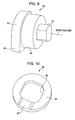
- the rotation regulating member 20 is substantially doughnut-shaped, with the center thereof provided with the cable insertion hole 21 having a diameter substantially equal to the diameter of the hole provided in the shaft body 19. Further, right and left end portions of the rotation regulating member 20 are cut off along the thickness direction, and respective surface portions obtained by the cutting-off form a first contact surface portion 22 and a second contact surface portion 23.
- the first contact surface portion 22 comes into contact with an end portion 40a of a second shaft member 40 illustrated in Fig. 3 .
- the second contact surface portion 23 comes into contact with an end portion 50a of a third shaft member 50 illustrated in Fig. 3 .
- the right and left end portions of the rotation regulating member 20 are cut off along the thickness direction such that, in the laterally opened state of the mobile phone, the width of the rotation regulating member 20 is substantially equal to the width of a gap 60 illustrated in Fig. 3 , which is formed between the end portion 40a of the second shaft member 40 and the end portion 50a of the third shaft member 50.
- the rotation regulating member 20 is provided with a projecting portion 24 projecting from one end portion of the first contact surface portion 22 in a direction substantially perpendicular to a longer direction of the first shaft member 11.
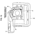
- the projecting portion 24 comes into contact with a stopper 31 provided to a second arm portion 30 illustrated in Fig. 13 , to thereby regulate the angle formed in the longitudinally opened state of the mobile phone to a predetermined angle.
- the above-described first shaft member 11 is provided with the shaft body 19 inserted into a shaft insertion hole 32 of the second arm portion 30 such that the rotation regulating member 20 is located on the side of the second arm portion 30.
- the longitudinal opening mechanism 5 is formed such that the shaft body 19 of the first shaft member 11 is inserted through the first cam member 12, the spring 13, and the first arm portion 14, and that the other end portion of the first shaft member 11 (i.e., an end portion opposite to the end portion provided with the rotation regulating member 20) is provided with a washer stopper.
- the first cam member 12, the spring 13, and the first arm portion 14 are prevented from dropping off from the shaft body 19.
- Fig. 6 is a perspective view of the first cam member 12, through which the first shaft member 11 is inserted.
- the overall shape of the first cam member 12 is a doughnut shape, and the first cam member 12 includes a shaft insertion hole 70 through which the shaft body 19 of the first shaft member 11 is inserted.
- the shaft insertion hole 70 forms a substantially D-shaped hole.
- a surface of the first cam member 12 is provided with two concave portions 73 and 74 across the shaft insertion hole 70.
- the concave portion 73 fits with a convex portion 33 provided to the second arm portion 30 illustrated in Fig. 3 .
- the concave portion 74 fits with the convex portion 33 provided to the second arm portion 30 illustrated in Fig. 3 .
- respective end portions in the circumferential direction of the concave portions 73 and 74 are tapered to form gradual slopes from the concave portions 73 and 74 to a cam surface 72.
- the spring 13 biases the thus configured first cam member 12 in the direction of the second arm portion 30.
- the first arm portion 14 includes an arm fixing portion 16 provided with a shaft insertion hole 15 through which the first shaft member 11 is inserted, and a case fixing portion 18 provided with screw holes 17 through which the first arm portion 14 is screwed onto the upper case 1.
- the shaft insertion hole 15 forms a substantially D-shaped hole.
- the lateral opening mechanism 6 includes the second and third shaft members 40 and 50, a housing 80, and the second arm portion 30.
- the second and third shaft members 40 and 50 function as a rotation axis (a lateral rotation axis) in the laterally opened state (see Fig. 2 ) of the mobile phone.
- the housing 80 which includes a fixing portion 81 fixed to the lower case 2 of the mobile phone by screws or the like, rotatably supports the second and third shaft members 40 and 50 such that the second and third shaft members 40 and 50 form the lateral rotation axis.
- the second arm portion 30 is supported by the second and third shaft members 40 and 50 and the housing 80 to rotate around the lateral rotation axis.
- the lateral opening mechanism 6 further includes a second cam member 36 which is brought into contact with a cam surface 35 of the second arm portion 30, and disc springs 37 which bias the second cam member 36 toward the cam surface 35 of the second arm portion 30.
- Fig. 5 only illustrates a single disc spring 37. However, it is desired to be understood that a plurality, e.g., three, of the disc springs 37 are actually provided.
- the second shaft member 40 has a substantially cylindrical shape provided with a cable insertion hole 41 extending along a longer direction thereof. As described later, a cable, a flexible board, or the like can be provided in the second shaft member 40 through the cable insertion hole 41.
- An outer circumferential portion of the second shaft member 40 includes a first outer circumferential portion 40b over which a first rotation supported portion 75 of the second arm portion 30 is located, a second outer circumferential portion 40c over which the second cam member 36 of the lateral opening mechanism 6 is located, and a third outer circumferential portion 40d which is inserted into the housing 80.
- the first outer circumferential portion 40b is formed to have an outer circumferential surface having no concavity and convexity along the circumferential direction. Therefore, the second arm portion 30 located over the first outer circumferential portion 40b is rotatably supported along the circumferential direction of the second shaft member 40.
- each of the second outer circumferential portion 40c over which the second cam member 36 is located and the third outer circumferential portion 40d which is inserted into the housing 80 is formed into a polygonal shape, i.e., a plurality of portions of the outer circumferential portions 40c and 40d are cut off along a longer direction of the second shaft member 40 such that the outer circumference of radial cross sections of the outer circumferential portions 40c and 40d obtained by cutting the second shaft member 40 along the radial direction has a polygonal shape (or a D-shape).
- a shaft insertion hole (a reference numeral 90 in Fig. 10 ) of the second cam member 36 provided to the second shaft member 40 is formed into a polygonal shape to fit the shape of the second outer circumferential portion 40c. Therefore, the second cam member 36 is fixedly provided to the second shaft member 40.
- the second shaft member 40 is provided to the housing 80, with the third outer circumferential portion 40d inserted into a shaft insertion hole 82 of the housing 80.
- the shaft insertion hole 82 of the housing 80 is formed into a polygonal shape to fit the shape of the third outer circumferential portion 40d of the second shaft member 40. Therefore, the second shaft member 40 is fixedly (non-rotatably) provided to the housing 80.
- the overall shape of the third shaft member 50 is formed by three disc members of a large diameter, a medium diameter, and a short diameter, respectively, which are substantially disc-shaped and coaxially-layered.
- the large-diameter disc member forms a stopper member 51 of the third shaft member 50, which includes a stopper projecting portion 54 projecting in a direction perpendicular to the direction of the rotation axis. Therefore, only the stopper member 51 has a teardrop shape.
- the stopper projecting portion 54 of the stopper member 51 comes into contact with a stopper convex portion 38 of the second arm portion 30 illustrated in Figs. 3 and 5 .
- the rotation angle formed between the upper case 1 and the lower case 2 is regulated to the predetermined rotation angle, e.g., 130 degrees.
- the medium-diameter disc member forms a rotation supporting portion 52 over which a second rotation supported portion 76 of the second arm portion 30 is located, and is formed to have an outer circumferential surface having no concavity and convexity along the circumferential direction. Therefore, the second arm portion 30 located over the rotation supporting portion 52 is rotatably supported along the circumferential direction of the third shaft member 50.
- the small-diameter disc member forms an insertion portion 53 inserted into a shaft insertion hole 83 of the housing 80.
- the insertion portion 53 two mutually facing outer circumferential portions are cut off along the direction of the rotation axis such that a radial cross section of the insertion portion 53 has a polygonal shape.
- the shaft insertion hole 83 of the housing 80 into which the insertion portion 53 is inserted, has a polygonal shape fitting the insertion portion 53.
- the second cam member 36 which is brought into contact with the cam surface 35 of the second arm portion 30 as illustrated in Figs. 3 and 5 , has a doughnut shape as illustrated in Fig. 10 , and includes a shaft insertion hole 90 through which the second shaft member 40 is inserted, and a convex portion 91 which is provided to a cam surface 92.
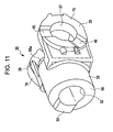
- the convex portion 91 fits in a first concave portion 45 provided in the cam surface 35 of the second arm portion 30 illustrated in Fig. 11 .
- a preset predetermined rotation angle e.g. 130 degrees
- the convex portion 91 fits in a second concave portion 46 provided in the cam surface 35 of the second arm portion 30.
- respective end portions in the circumferential direction of the convex portion 91 are tapered to form gradual slopes from the cam surface 92 to the respective end portions of the convex portion 91.
- the disc springs 37 as illustrated in Fig. 5 bias the above-described second cam member 36 in the direction of the second arm portion 30.
- Fig. 11 illustrates a perspective view of the second arm portion 30 as viewed from the side of the shaft insertion hole 32
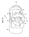
- Fig. 12 illustrates a perspective view of the second arm portion 30 as viewed from the side of the first rotation supported portion 75.
- the second arm portion 30 has a shape in which the first rotation supported portion 75 and the second rotation supported portion 76 are connected to an outer circumferential portion near an other end portion 55a of a substantially cylindrically shaped shaft supporting portion 55 to face each other.
- the shaft supporting portion 55 of the second arm portion 30 includes the shaft insertion hole 32, which extends along a longer direction of the shaft supporting portion 55 to be coaxial with the shaft supporting portion 55, and rotatably supports the first shaft member 11 inserted into the shaft insertion hole 32.
- one end portion of the shaft supporting portion 55 opposite to the other end portion 55a forms a cam surface 56 which comes into contact with the cam surface 72 of the first cam member 12 described with reference to Fig. 6 .
- the cam surface 56 of the shaft supporting portion 55 is provided with the convex portion 33.
- the convex portion 33 fits in the concave portion 73 of the first cam member 12 in the closed state of the mobile phone, and fits in the concave portion 74 of the first cam member 12 when the rotation angle of the mobile phone in the longitudinal opening operation reaches a preset predetermined rotation angle, e.g., 170 degrees.
- the first rotation supported portion 75 includes a shaft insertion hole 57 which extends along a direction perpendicular to the radial direction of the first rotation supported portion 75 to be coaxial with the first rotation supported portion 75.
- the cam surface 35 of the first rotation supported portion 75 is provided with the first concave portion 45 and the second concave portion 46.
- the first concave portion 45 fits with the convex portion 91 of the second cam member 36, which has been described with reference to Fig. 10 .
- the second concave portion 46 fits with the convex portion 91 of the second cam member 36.
- the second rotation supported portion 76 includes a shaft insertion hole 58 which extends along a direction perpendicular to the radial direction of the second rotation supported portion 76 to be coaxial with the second rotation supported portion 76.
- the second arm portion 30 is provided with the stopper convex portion 38 located at a position adjacent to the second rotation supported portion 76.
- the stopper convex portion 38 is formed by a projecting portion of the other end portion 55a of the shaft supporting portion 55.
- the first arm portion 14 of the biaxial hinge unit 3 is screwed onto the upper case 1. Therefore, if the upper case 1 is rotated in the above-described manner, the first arm portion 14 is rotated in the longitudinal opening direction illustrated in Fig. 3 . As described above, the first arm portion 14 is fixed to the first shaft member 11. Therefore, the first shaft member 11 is rotated in the longitudinal opening direction along with the rotation of the first arm portion 14.
- the first shaft member 11 is provided with the first cam member 12 fixed thereto, which has been described with reference to Fig. 6 .
- the first cam member 12 is biased by the spring 13 such that the cam surface 72 comes into contact with the cam surface 56 of the second arm portion 30 into which the first shaft member 11 is inserted.
- the concave portion 73 provided in the cam surface 72 of the first cam member 12 fits with the convex portion 33 provided to the cam surface 56 of the second arm portion 30. If the upper case 1 is rotated in the longitudinal opening direction, the first shaft member 11 is rotated in the longitudinal opening direction via the first arm portion 14. Along with this rotation, the first cam member 12 is rotated in the longitudinal opening direction, and the fitted engagement between the concave portion 73 of the first cam member 12 and the convex portion 33 of the second arm portion 30 is released.
- the angle formed between the upper case 1 and the lower case 2 reaches approximately 170 degrees, for example, the concave portion 74 formed in the cam surface 72 of the first cam member 12 fits with the convex portion 33 provided to the cam surface 56 of the second arm portion 30.
- the angle formed between the upper case 1 and the lower case 2 is regulated to approximately 170 degrees, for example, and the mobile phone is brought into the longitudinally opened state illustrated in Fig. 1 .
- the first cam member 12 is applied with biasing force by the spring 13. Therefore, when the angle formed between the upper case 1 and the lower case 2 reaches the approximately 170 degrees and the concave portion 74 and the convex portion 33 fit with each other again, a so-called click sound is produced. With the click sound, the user recognizes that the mobile phone has been brought into the longitudinally opened state.
- the projecting portion 24 provided to the rotation regulating member 20 of the first shaft member 11 moves to a position substantially adjacent to the stopper 31 provided to the second arm portion 30. Then, if the user attempts to perform an opening operation to have the longitudinal angle formed between the upper case 1 and the lower case 2 exceed the 170 degrees, the projecting portion 24 provided to the rotation regulating member 20 comes into contact with the stopper 31 of the second arm portion 30 illustrated in Fig. 13 , to thereby regulate the longitudinal opening operation performed by the user. Accordingly, the longitudinal angle formed between the upper case 1 and the lower case 2 can be regulated to approximately 170 degrees plus 1 to 3 degrees. It is therefore possible to prevent inconvenience of damage to the mobile phone caused by the forcible longitudinal opening operation performed by the user.
- the second arm portion 30 is screwed onto the lower case 2 via the housing 80. Further, the first shaft member 11 provided with the first arm portion 14 fixed to the upper case 1 is inserted into the shaft insertion hole 32 of the second arm portion 30. Therefore, if the upper case 1 is rotated in the lateral opening direction in the above-described manner, the second arm portion 30 is rotated in the lateral opening direction illustrated in Fig. 3 . As described with reference to Fig. 11 , due to the biasing action of the disc springs 37 as illustrated in Fig. 5 , the cam surface 35 of the second arm portion 30 is in contact with the cam surface 92 of the second cam member 36 fixedly provided to the second shaft member 40.
- the convex portion 91 provided to the cam surface 92 of the second cam member 36 fits in the first concave portion 45 provided in the cam surface 35 of the second arm portion 30. If the upper case 1 is rotated in the lateral opening direction and thus the second arm portion 30 is rotated in the lateral opening direction, the fitted engagement between the convex portion 91 of the second cam member 36 and the first concave portion 45 of the second arm portion 30 is released.
- the angle formed between the upper case 1 and the lower case 2 is regulated to approximately 130 degrees, for example, and the mobile phone is brought into the laterally opened state illustrated in Fig. 2 .
- the second cam member 36 is applied with the biasing force by the disc springs 37. Therefore, when the angle formed between the upper case 1 and the lower case 2 reaches the approximately 130 degrees and the convex portion 91 fits in the second concave portion 46, a so-called click sound is produced. With the click sound, the user recognizes that the mobile phone has been brought into the laterally opened state.
- the stopper convex portion 38 provided to the second arm portion 30 as illustrated in Figs. 11 and 12 moves to a position substantially adjacent to the stopper projecting portion 54 of the third shaft member 50 illustrated in Figs. 3 , 5 , and 9 .
- the stopper convex portion 38 provided to the second arm portion 30 comes into contact with the stopper projecting portion 54 of the third shaft member 50, to thereby regulate the opening operation performed by the user.
- the lateral angle formed between the upper case 1 and the lower case 2 can be regulated to approximately 130 degrees plus 1 to 3 degrees. It is therefore possible to prevent inconvenience of damage to the mobile phone caused by the forcible lateral opening operation performed by the user.
- the right and left end portions of the rotation regulating member 20 are cut off along the thickness direction. That is, the right and left end portions of the rotation regulating member 20 are cut off along the thickness direction such that the width of the rotation regulating member 20 is substantially equal to the width of the gap 60 illustrated in Figs. 3 and 5 , which is formed between the end portion 40a of the second shaft member 40 and the end portion 50a of the third shaft member 50.
- the respective surface portions obtained by the cutting-off form the first contact surface portion 22 and the second contact surface portion 23.
- the first contact surface portion 22 comes into contact with the end portion 40a of the second shaft member 40 illustrated in Fig. 5 .
- the second contact surface portion 23 comes into contact with the end portion 50a of the third shaft member 50 illustrated in Fig. 5 .
- the rotation regulating member 20 of the first shaft member 11 is sandwiched and held by the end portion 40a of the second shaft member 40 and the end portion 50a of the third shaft member 50. Therefore, even if the longitudinal opening operation of the mobile phone is attempted in the laterally opened state of the mobile phone, the rotation of the first shaft member 11 is regulated via the rotation regulating member 20, with the end portion 40a of the second shaft member 40 or the end portion 50a of the third shaft member 50 acting as a wall. Accordingly, it is possible to regulate the longitudinal opening operation in the laterally opened state of the mobile phone.
- a cable 100, a flexible board, or the like can be wired through the cable insertion hole 21 of the cylindrically shaped first shaft member 11 and the cable insertion hole 41 of the cylindrically shaped second shaft member 40, as illustrated in Fig. 3 .
- the first shaft member 11 includes the cable insertion hole 21 passing therethrough in the extending direction thereof.
- the second shaft member 40 includes the cable insertion hole 41 passing therethrough in the extending direction thereof.
- an electrical component such as a display unit provided to the upper case 1 and an electrical component such as a circuit board provided to the lower case 2, for example, are electrically connected to each other by the cable 100 wired through the cable insertion hole 21 provided in the first shaft member 11 and the cable insertion hole 41 provided in the second shaft member 40. Therefore, both in the longitudinal opening operation and the lateral opening operation performed by the user, it is possible to prevent inconvenience of twisting of the cable 100, and thus to prevent inconvenience such as cutting-off of the cable 100 resulting from the twisting caused by the respective operations.
- the biaxial hinge unit 3 can be reduced in size.
- the substantially cylindrically shaped second shaft member 40 is fixedly provided to the housing 80 fixed to the lower case 2, to thereby form the rotation axis for the lateral opening operation.
- first shaft member 11 is rotatably inserted into the shaft insertion hole 32 of the second arm portion 30, to thereby form the rotation axis for the longitudinal opening operation.
- first arm portion 14 fixed to the upper case 1 is fixedly provided to the first shaft member 11.
- the cable 100 (or the flexible board or the like) for electrically connecting an electrical component of the upper case 1 to an electrical component of the lower case 2 is wired through the cable insertion hole 21 provided along the longer direction of the substantially cylindrically shaped first shaft member 11 to be coaxial with the first shaft member 11 and through the cable insertion hole 41 provided along the longer direction of the substantially cylindrically shaped second shaft member 40 to be coaxial with the second shaft member 40.
- the biaxial hinge unit 3 can be reduced in size.
- the disc springs 37 are used to bias the second cam member 36 for regulating the rotation angle formed between the upper case 1 and the lower case 2 in the lateral opening operation (see Fig. 5 ). Therefore, as compared with a configuration using a spring as a biasing member, the present embodiment can substantially reduce the space occupied by the biasing member. Due to the substantial reduction of the space occupied by the biasing member, therefore, the biaxial hinge unit 3 can be reduced in size.
- the spring 13 is used to bias the fist cam member 12 for regulating the rotation angle formed between the upper case 1 and the lower case 2 in the longitudinal opening operation.
- a plurality of superimposed disc springs may be used in place of the spring 13. With this configuration, the space occupied by the spring 13 can also be substantially reduced. Accordingly, the biaxial hinge unit 3 can be further reduced in size.
- the present invention is applied to a mobile phone.
- the present invention may also be applied to another device, such as a PHS (Personal Handyphone System) phone, a PDA (Personal Digital Assistant) device, a mobile game device, a digital camera device, and a notebook personal computer device.
- PHS Personal Handyphone System
- PDA Personal Digital Assistant
Landscapes
- Engineering & Computer Science (AREA)
- Signal Processing (AREA)
- Computer Networks & Wireless Communication (AREA)
- Pivots And Pivotal Connections (AREA)
- Telephone Set Structure (AREA)
Applications Claiming Priority (1)
| Application Number | Priority Date | Filing Date | Title |
|---|---|---|---|
| JP2008072322A JP2009228713A (ja) | 2008-03-19 | 2008-03-19 | 二軸ヒンジ装置、及び携帯端末装置 |
Publications (1)
| Publication Number | Publication Date |
|---|---|
| EP2104321A1 true EP2104321A1 (de) | 2009-09-23 |
Family
ID=40789056
Family Applications (1)
| Application Number | Title | Priority Date | Filing Date |
|---|---|---|---|
| EP09250370A Withdrawn EP2104321A1 (de) | 2008-03-19 | 2009-02-13 | Zweiachsige Scharniervorrichtung und tragbares Endgerät |
Country Status (5)
| Country | Link |
|---|---|
| US (1) | US8136205B2 (de) |
| EP (1) | EP2104321A1 (de) |
| JP (1) | JP2009228713A (de) |
| KR (1) | KR20090100286A (de) |
| CN (1) | CN101539165B (de) |
Families Citing this family (9)
| Publication number | Priority date | Publication date | Assignee | Title |
|---|---|---|---|---|
| JP2009236315A (ja) * | 2008-03-07 | 2009-10-15 | Sony Ericsson Mobilecommunications Japan Inc | 二軸ヒンジ装置、及び携帯端末装置 |
| WO2010073436A1 (ja) * | 2008-12-26 | 2010-07-01 | 三菱電機株式会社 | 2軸ヒンジ機構のfpc固定構造 |
| CN102356208A (zh) * | 2009-02-20 | 2012-02-15 | 葛芬益普斯有限公司 | 可调节铰链 |
| JP5975173B2 (ja) * | 2013-04-30 | 2016-08-23 | 富士通株式会社 | 分割筐体の結合装置及び分割筐体を備えた電子装置 |
| CN106931288B (zh) * | 2017-05-10 | 2023-11-28 | 合肥联宝信息技术有限公司 | 支架组件及电子设备 |
| CN109302513B (zh) * | 2018-11-28 | 2021-03-23 | 维沃移动通信有限公司 | 折叠式移动终端 |
| CN111720425B (zh) * | 2020-06-30 | 2021-07-27 | 广东虹勤通讯技术有限公司 | 用于电子设备的转轴装置及电子设备 |
| WO2023017946A1 (ko) * | 2021-08-09 | 2023-02-16 | 삼성전자 주식회사 | 힌지 구조 및 이를 포함하는 폴더블 전자 장치 |
| KR102880879B1 (ko) | 2021-09-27 | 2025-11-04 | 삼성전자주식회사 | 힌지 어셈블리 및 이를 포함하는 전자 장치 |
Citations (4)
| Publication number | Priority date | Publication date | Assignee | Title |
|---|---|---|---|---|
| JP2005198062A (ja) | 2004-01-08 | 2005-07-21 | Matsushita Electric Ind Co Ltd | 折り畳み式携帯電話装置 |
| US20070037616A1 (en) * | 2005-08-09 | 2007-02-15 | Kuo-Wei Hung | Hinge and mobile phone with the hinge |
| EP1764672A1 (de) * | 2005-09-15 | 2007-03-21 | High Tech Computer Corp. | Zweiachsiges Scharnier |
| EP1791330A1 (de) * | 2005-11-28 | 2007-05-30 | Samsung Electronics Co.,Ltd. | Tragbares Endgerät mit einem, zwei Drehachsen umfassenden Scharnier |
Family Cites Families (18)
| Publication number | Priority date | Publication date | Assignee | Title |
|---|---|---|---|---|
| JP3390718B2 (ja) * | 2000-02-18 | 2003-03-31 | 株式会社ストロベリーコーポレーション | 二軸ヒンジ装置 |
| JP2003110673A (ja) * | 2001-09-28 | 2003-04-11 | Sanyo Electric Co Ltd | 折畳式携帯電話装置 |
| JP2003120653A (ja) * | 2001-10-17 | 2003-04-23 | Ohashi Technica Inc | ヒンジ装置及びそれを用いた携帯電話機 |
| KR100594106B1 (ko) * | 2004-01-27 | 2006-06-30 | 삼성전자주식회사 | 휴대용 단말기의 로터리형 힌지 장치 |
| JP2005337301A (ja) * | 2004-05-24 | 2005-12-08 | Kato Electrical Mach Co Ltd | ヒンジ装置並びにこのヒンジ装置を用いた電子機器 |
| US7055218B2 (en) * | 2004-06-01 | 2006-06-06 | Shin Zu Shing Co., Ltd. | Hinge |
| JP2006010025A (ja) * | 2004-06-29 | 2006-01-12 | Matsushita Electric Ind Co Ltd | 2軸ヒンジおよびこれを備えた携帯情報端末 |
| US7532459B2 (en) * | 2005-04-22 | 2009-05-12 | Samsung Electronics Co., Ltd. | Hinge apparatus and portable terminal having the same |
| JP4546888B2 (ja) * | 2005-07-08 | 2010-09-22 | 株式会社ストロベリーコーポレーション | ヒンジ装置並びにヒンジ装置を用いた電子機器 |
| JP2007113686A (ja) * | 2005-10-20 | 2007-05-10 | Fujitsu Ltd | 携帯端末およびヒンジ機構 |
| US20070174997A1 (en) * | 2006-01-27 | 2007-08-02 | Shin Zu Shing Co., Ltd. | Suspension hinge |
| TWM304715U (en) * | 2006-06-23 | 2007-01-11 | Quanta Comp Inc | Hinge device with auto-lock function |
| TWM304879U (en) * | 2006-08-09 | 2007-01-11 | Jarllytec Co Ltd | Multi-tasking spindle structure |
| JP4444250B2 (ja) * | 2006-08-11 | 2010-03-31 | パナソニック株式会社 | 開閉式の通信端末 |
| US7526835B2 (en) * | 2006-09-07 | 2009-05-05 | Shin Zu Shing Co. Ltd. | Stable hinge |
| US7533449B2 (en) * | 2006-10-16 | 2009-05-19 | Shin Zu Shing Co., Ltd. | Hinge to improve panel stability |
| TWM309324U (en) * | 2006-10-31 | 2007-04-01 | Jarllytec Co Ltd | Spindle structure preventing sway |
| KR100842529B1 (ko) * | 2007-02-22 | 2008-07-01 | 삼성전자주식회사 | 힌지 장치를 구비하는 휴대용 단말기 |
-
2008
- 2008-03-19 JP JP2008072322A patent/JP2009228713A/ja active Pending
-
2009
- 2009-02-13 EP EP09250370A patent/EP2104321A1/de not_active Withdrawn
- 2009-03-17 CN CN2009101284349A patent/CN101539165B/zh not_active Expired - Fee Related
- 2009-03-18 US US12/406,182 patent/US8136205B2/en not_active Expired - Fee Related
- 2009-03-18 KR KR1020090022855A patent/KR20090100286A/ko not_active Withdrawn
Patent Citations (4)
| Publication number | Priority date | Publication date | Assignee | Title |
|---|---|---|---|---|
| JP2005198062A (ja) | 2004-01-08 | 2005-07-21 | Matsushita Electric Ind Co Ltd | 折り畳み式携帯電話装置 |
| US20070037616A1 (en) * | 2005-08-09 | 2007-02-15 | Kuo-Wei Hung | Hinge and mobile phone with the hinge |
| EP1764672A1 (de) * | 2005-09-15 | 2007-03-21 | High Tech Computer Corp. | Zweiachsiges Scharnier |
| EP1791330A1 (de) * | 2005-11-28 | 2007-05-30 | Samsung Electronics Co.,Ltd. | Tragbares Endgerät mit einem, zwei Drehachsen umfassenden Scharnier |
Also Published As
| Publication number | Publication date |
|---|---|
| JP2009228713A (ja) | 2009-10-08 |
| US8136205B2 (en) | 2012-03-20 |
| KR20090100286A (ko) | 2009-09-23 |
| US20090235487A1 (en) | 2009-09-24 |
| CN101539165A (zh) | 2009-09-23 |
| CN101539165B (zh) | 2011-09-07 |
Similar Documents
| Publication | Publication Date | Title |
|---|---|---|
| EP2104321A1 (de) | Zweiachsige Scharniervorrichtung und tragbares Endgerät | |
| JP5015871B2 (ja) | 二軸ヒンジ装置、及び携帯端末装置 | |
| JP5112121B2 (ja) | 2軸ヒンジ装置並びに電子機器 | |
| JP2009236315A (ja) | 二軸ヒンジ装置、及び携帯端末装置 | |
| US10000955B2 (en) | Biaxial hinge and terminal device using the same | |
| JP2009264460A (ja) | 二軸ヒンジ装置、及び携帯端末装置 | |
| JP4113092B2 (ja) | 二軸ヒンジの回転機構およびこれを備えた携帯電話 | |
| EP1381207A2 (de) | Mobiles Endgerät mit drehbar gelagertem Kameraobjektive | |
| KR100988680B1 (ko) | 회전규제기능 부착 2축 힌지 장치 | |
| JP2013072442A (ja) | ヒンジ装置、およびそれを備えた電子機器 | |
| JP5135957B2 (ja) | ヒンジ装置及びそのヒンジ装置を備えた機器 | |
| JP2009030733A (ja) | 折り畳み式電子機器 | |
| JP2009063030A (ja) | ヒンジ装置及びそのヒンジ装置を備えた機器 | |
| JP2011082737A (ja) | 折り畳み式携帯端末 | |
| US20060285681A1 (en) | Foldable electronic devices | |
| JP2009174557A (ja) | ヒンジ装置及びそのヒンジ装置を備えた機器 | |
| JP5112990B2 (ja) | ヒンジユニット | |
| CN101729615B (zh) | 一种便携式终端 | |
| JP2008089049A (ja) | ヒンジ装置及びヒンジ装置を備える機器 | |
| JP5334191B2 (ja) | ヒンジ構造、及び携帯機器 | |
| JP2007195048A (ja) | 電子機器 | |
| JP2008106793A (ja) | 携帯通信機 | |
| JP2008057714A (ja) | 開閉装置 | |
| JP2012087915A (ja) | ヒンジ機構 |
Legal Events
| Date | Code | Title | Description |
|---|---|---|---|
| PUAI | Public reference made under article 153(3) epc to a published international application that has entered the european phase |
Free format text: ORIGINAL CODE: 0009012 |
|
| 17P | Request for examination filed |
Effective date: 20090224 |
|
| AK | Designated contracting states |
Kind code of ref document: A1 Designated state(s): AT BE BG CH CY CZ DE DK EE ES FI FR GB GR HR HU IE IS IT LI LT LU LV MC MK MT NL NO PL PT RO SE SI SK TR |
|
| AX | Request for extension of the european patent |
Extension state: AL BA RS |
|
| 17Q | First examination report despatched |
Effective date: 20091028 |
|
| AKX | Designation fees paid |
Designated state(s): DE FR GB |
|
| RAP1 | Party data changed (applicant data changed or rights of an application transferred) |
Owner name: SONY MOBILE COMMUNICATIONS JAPAN, INC. |
|
| GRAP | Despatch of communication of intention to grant a patent |
Free format text: ORIGINAL CODE: EPIDOSNIGR1 |
|
| INTG | Intention to grant announced |
Effective date: 20141030 |
|
| STAA | Information on the status of an ep patent application or granted ep patent |
Free format text: STATUS: THE APPLICATION IS DEEMED TO BE WITHDRAWN |
|
| 18D | Application deemed to be withdrawn |
Effective date: 20150310 |