EP2104338A2 - Système autofocus - Google Patents
Système autofocus Download PDFInfo
- Publication number
- EP2104338A2 EP2104338A2 EP09002038A EP09002038A EP2104338A2 EP 2104338 A2 EP2104338 A2 EP 2104338A2 EP 09002038 A EP09002038 A EP 09002038A EP 09002038 A EP09002038 A EP 09002038A EP 2104338 A2 EP2104338 A2 EP 2104338A2
- Authority
- EP
- European Patent Office
- Prior art keywords
- subject
- unit
- tracking
- registered
- tracking target
- Prior art date
- Legal status (The legal status is an assumption and is not a legal conclusion. Google has not performed a legal analysis and makes no representation as to the accuracy of the status listed.)
- Withdrawn
Links
- 238000003384 imaging method Methods 0.000 claims description 65
- 238000001514 detection method Methods 0.000 claims description 44
- 230000003287 optical effect Effects 0.000 claims description 13
- 238000013500 data storage Methods 0.000 abstract description 11
- 238000000034 method Methods 0.000 description 124
- 238000011156 evaluation Methods 0.000 description 9
- 238000010586 diagram Methods 0.000 description 6
- 230000002194 synthesizing effect Effects 0.000 description 6
- 238000005070 sampling Methods 0.000 description 5
- 235000010724 Wisteria floribunda Nutrition 0.000 description 3
- 239000003086 colorant Substances 0.000 description 3
- 238000007630 basic procedure Methods 0.000 description 1
- 230000009194 climbing Effects 0.000 description 1
- 239000000203 mixture Substances 0.000 description 1
- 238000003909 pattern recognition Methods 0.000 description 1
Images





Classifications
-
- H—ELECTRICITY
- H04—ELECTRIC COMMUNICATION TECHNIQUE
- H04N—PICTORIAL COMMUNICATION, e.g. TELEVISION
- H04N23/00—Cameras or camera modules comprising electronic image sensors; Control thereof
- H04N23/60—Control of cameras or camera modules
- H04N23/67—Focus control based on electronic image sensor signals
- H04N23/673—Focus control based on electronic image sensor signals based on contrast or high frequency components of image signals, e.g. hill climbing method
-
- H—ELECTRICITY
- H04—ELECTRIC COMMUNICATION TECHNIQUE
- H04N—PICTORIAL COMMUNICATION, e.g. TELEVISION
- H04N23/00—Cameras or camera modules comprising electronic image sensors; Control thereof
- H04N23/60—Control of cameras or camera modules
- H04N23/67—Focus control based on electronic image sensor signals
- H04N23/675—Focus control based on electronic image sensor signals comprising setting of focusing regions
-
- H—ELECTRICITY
- H04—ELECTRIC COMMUNICATION TECHNIQUE
- H04N—PICTORIAL COMMUNICATION, e.g. TELEVISION
- H04N23/00—Cameras or camera modules comprising electronic image sensors; Control thereof
- H04N23/60—Control of cameras or camera modules
- H04N23/61—Control of cameras or camera modules based on recognised objects
-
- H—ELECTRICITY
- H04—ELECTRIC COMMUNICATION TECHNIQUE
- H04N—PICTORIAL COMMUNICATION, e.g. TELEVISION
- H04N23/00—Cameras or camera modules comprising electronic image sensors; Control thereof
- H04N23/60—Control of cameras or camera modules
- H04N23/61—Control of cameras or camera modules based on recognised objects
- H04N23/611—Control of cameras or camera modules based on recognised objects where the recognised objects include parts of the human body
-
- H—ELECTRICITY
- H04—ELECTRIC COMMUNICATION TECHNIQUE
- H04N—PICTORIAL COMMUNICATION, e.g. TELEVISION
- H04N23/00—Cameras or camera modules comprising electronic image sensors; Control thereof
- H04N23/60—Control of cameras or camera modules
- H04N23/63—Control of cameras or camera modules by using electronic viewfinders
- H04N23/633—Control of cameras or camera modules by using electronic viewfinders for displaying additional information relating to control or operation of the camera
- H04N23/635—Region indicators; Field of view indicators
Definitions
- the invention relates to an autofocus system, and more particularly to an autofocus system capable of performing focus adjustment while tracking a desired subject (person) by automatically moving an autofocus (AF) target position (range) in a shooting range of a camera.
- AF autofocus
- range target position
- AF area auto-tracking system that is adapted to change autofocus (AF) area in accordance with movement of a subject in order to bring the subject into focus when a quickly moving subject in sporting scenes such as a soccer and a figure skating is shot by, for example, a TV camera and the like (for example, see JP 2006-267221 A (corresponding to US 2006/0140612 A ).
- a contrast mode is generally adopted as an autofocus (AF) mode.
- the contrast mode is to detect the contrast of a subject image from an image signal acquired by an imaging device, and control focus of a taking lens so that the highest contrast can be obtained, thereby automatically bring the subject into best focus.
- the entire subject in the shooting range of a camera is not set to the target of the AF, but only a subject in a part of the shooting range is processed as the AF target in many cases.
- the image signals in the target range of the AF are extracted from the image signals acquired from the entire imaging area of the imaging device, and the target of the AF is limited only to the subject in a part of the range by controlling the focus so that the contrast of the extracted image signal in that range is maximized.
- a subject range being a target of the AF
- a shooting range of a camera or an image range of a target subject being a target of the AF
- a shot image of a camera will be referred to as an "AF area”
- a frame indicating an outline of the AF area will be referred to as an "AF frame”.
- a cameraman performs a pan/tilt (P/T) operation and a zooming operation in order to capture a quickly moving subject like a figure skater.
- P/T pan/tilt
- zooming operation in order to capture a quickly moving subject like a figure skater.
- it is very difficult to move the AF area.
- the above-mentioned AF area auto-tracking system is useful.
- the invention has been made in view of the above circumstances and provides an autofocus system capable of performing auto-tracking by setting a specific subject (person's face or the like) as a target of the AF.
- Fig. 1 is a block diagram showing the overall configuration of the imaging system to which the autofocus system according to an embodiment of the invention is applied.
- the imaging system shown in the drawing is, for example, an imaging system that is used to shoot an image by a TV camera for broadcast.
- Fig. 1 shows a camera head 10 whose lens can be replaced, a lens device 12 that has a taking lens (optical system) attached to a lens mount of the camera head 10, a tracking device 16 that includes an operation unit 14, and the like.
- the camera head 10 is mounted with an imaging device (for example, a CCD), a signal processing circuit, and the like.
- An image formed by the taking lens of the lens device 12 is photoelectrically converted by the imaging device, and then signal processing is performed for the image by the signal processing circuit.
- a video signal of a certain format is generated by the signal processing circuit, and is output from a video signal output terminal or the like of the camera head 10 to an external equipment.
- the camera head 10 is provided with a viewfinder (monitor) 18.
- a real-time image (video) that is currently being shot by the imaging device of the camera head 10 is displayed to check composition thereof. That is, a video signal of the video, which is currently being shot by the imaging device, is output from the camera head 10, the video signal is input to the viewfinder 18 through a video synthesizing unit 36 of the tracking device 16 (which will be described later), and the video signal is displayed as a real-time image that is currently being shot on a screen of the viewfinder 18.
- the viewfinder 18 may be set or disposed on an optional location other than the camera head 10.
- the lens device 12 is provided with the taking lens (optical system), which is not shown in the drawings and is attached to the lens mount of the camera head 10.
- the taking lens forms an image of a subject on an imaging surface of the imaging device of the camera head 10.
- the taking lens includes, as its elements, movable portions for adjusting a shooting condition.
- the movable portions such as a focus lens group, a zoom lens group, and an aperture diaphragm are electrically driven by a motor (servomechanism) not shown in the drawings.
- the focus lens group and the zoom lens group move in an optical axis direction, the movement of the focus lens group adjusts a focus (subject distance), and the movement of the zoom lens group adjusts a focal length (zoom power).
- At least the focus lens group may be electrically driven, and the other movable portions may be only driven manually.
- the certain movable portion is controlled based on control signals output from an operation unit (an operation unit of a controller connected to the lens device 12 or the like), which is not shown in the drawings, in accordance with the operator's operation, but details thereon are omitted here.
- the lens device 12 is mounted with a lens CPU 20 for integrally controlling the entire lens device 12, an AF processing unit 22 that executes autofocus (AF) processing, an AF imaging circuit 24, and the like.
- the AF imaging circuit 24 is disposed on the lens device 12 in order to acquire a video signal for AF process.
- the AF imaging circuit 24 includes the imaging device (CCD or the like) and the processing circuit for outputting an output signal of the imaging device as the video signal in the certain format, and the like.
- the imaging device of the AF imaging circuit 24 may be referred to as an "AF imaging device". It is assumed that the video signal output from the AF imaging circuit 24 is a luminance signal.
- Light is branched from subject light incident on the imaging device of the camera head 10 by the use of a half mirror or the like disposed on a light path of the taking lens, and the branched light forms an image on the imaging surface of the AF imaging device.
- a shooting range and a subject distance (a distance at which a subject can be focused to) for an imaging area of the AF imaging device are configured to match a shooting range and a subject distance for an imaging area of the imaging device of the camera head 10.
- a subject image acquired by the AF imaging device substantially matches a subject image acquired by the imaging device of the camera head 10. It is not necessary for the both shooting ranges to be completely matching.
- the shooting range of the AF imaging device may be large enough to contain include the shooting range of the imaging device of the camera head 10.
- the AF processing unit 22 acquires the video signal from the AF imaging circuit 24, and calculates a focus evaluation value indicating a level of a contrast of the subject image based on the video signal. For example, high-frequency component signals of the video signal acquired from the AF imaging device are extracted by a high-pass filter, and then of the high-frequency component signals, signals in a range corresponding to an AF area (a subject area to be brought into focus by the AF) that is an AF target range are integrated for each screen (frame). An integrated value thus acquired for each screen indicates the level of the contrast of the subject image, and is given to the lens CPU 20 as the focus evaluation value. Furthermore, the range of the AF area is designated by the lens CPU 20 as will be described later.
- the lens CPU 20 acquires information (AF frame information) of the AF frame indicating a range (outline) of the AF area from an operation unit 14 of the tracking device 16, and informs of the AF processing circuit 22 a range in the AF frame that is designated by the AF range information as the AF area.
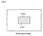
- Fig. 2 shows an example of the AF area (AF frame), in which the AF area having a rectangular shape is set in the shooting range and the outline thereof corresponds to the AF frame.
- the lens CPU 20 informs the AF processing circuits 22 of the above-mentioned AF area, and then acquires from the AF processing unit 22 the focus evaluation value, which is acquired from the image (video signal) in the AF area.
- the lens CPU 20 acquires the focus evaluation value from the AF processing unit 22, and controls the focus lens group so as to maximize the acquired focus evaluation value (to take a local maximum value), that is, maximize the contrast of the subject image in the AF area.
- a climbing mode is generally known as a mode of controlling the focus lens group based on the focus evaluation value. In this mode, the focus lens group is moved in a direction for increasing the focus evaluation value, and then if a point at which the focus evaluation value starts to decrease is detected, the focus lens group is set to the detected point. Thus, it is possible to automatically bring the subject in the AF frame into focus.
- the AF processing unit 22 is configured to acquire the video signal for detecting the contrast of the subject image from the AF imaging circuit 24, which is mounted on the lens device 12.
- the video signal acquired from the video shot by the imaging device of the camera head 10 may be acquired from the camera head 10.
- the AF mode is not limited to the contrast mode mentioned above.
- the tracking device 16 is a device for tracking a certain subject (person's face or the like) on the screen in order to keep the certain subject being within the AF area.
- the tracking device 16 includes the operation unit 14, an image processing unit 26, an image input unit 28, a tracking processing unit 30, a pattern data storage unit 32, a frame information generation unit 34, a video synthesizing unit 36, and the like.
- the following basic processes are performed. That is, the basic procedures include: an AF area setting process for setting (determining) an AF area (AF frame) that is used in the AF processing unit 22 of the lens device 12; an auto-tracking process for automatically tracking a tracking target object; a person specification process for recognizing (detecting) a face image of a person in a shot video and specifying a person of the recognized face image; a pattern registration process for registering a pattern of the face image of the person specified by the person specification process; a frame display process for displaying the shot video together with an AF frame or a tracking frame (face frame) on a viewfinder 18. These processes are adapted to be integrally performed by the tracking processing unit 30.
- the AF area setting process is a process for setting a range (position, size, shape) of the AF area (AF frame) and transmitting AF frame information indicating the set an AF area range to the lens CPU 20 of the lens device 12. Thereby, the lens CPU 20 sets the AF area, which is used in the AF processing unit 22, in accordance with the AF frame information.
- the auto-tracking process is performed by the tracking processing unit 30, and a position of the AF area and the like are changed and set in accordance with a position of the tracking target, which is the AF target. Then, the AF frame information indicating the AF area range set by the tracking processing unit 30 is transmitted to the lens CPU 20 of the lens device 12 through the operation unit 14.
- the AF area range is fixed unless an operator performs an operation for changing the AF area range using the operation unit 14. For example, at an initial state, a rectangular area that has a predetermined size and is located in the center of the screen (shooting range) is set as the AF area.
- the AF area range is changed in accordance with the manual operation.
- the operation unit 14 is provided with a track ball 14a.
- a new AF area position is obtained by moving an AF area from the current AF area position in a moving direction corresponding to an operation direction of the track ball 14a and by a moving distance corresponding to an operation amount of the track ball 14a.
- AF frame information indicating a range of the changed AF area is transmitted to the lens CPU 20 of the lens device 12, and the AF area position is set in accordance with the operation of the track ball 14a.
- the operation unit 14 is provided with other elements not shown in the drawings.
- the other components include, for example, detection circuits (sensor, switch, and the like) for detecting operations of the respective operation members and a simple processing unit for generating required information such as AF frame information based on output signals of these detection circuits and outputting the generated information to the lens device 12 and/or the tracking processing unit 30.
- detection circuits sensor, switch, and the like
- a simple processing unit for generating required information such as AF frame information based on output signals of these detection circuits and outputting the generated information to the lens device 12 and/or the tracking processing unit 30.
- all of processes performed in the processing unit of the operation unit 14 may be performed in the tracking processing unit 30, which acquires the outputs of the detection circuits of the operation unit 14, and the information (AF frame information and the like) required for the lens CPU 20 may be transmitted directly from the tracking processing unit 30.
- the output signals required for processes of the tracking processing unit 30 and the lens CPU 20
- the operation unit 14 is an element included in the tracking device 16, but may be formed as a device that is separate from the tracking device 16, and may be adapted to be connected to the tracking device 16 via a cable or the like.
- the auto-tracking process is a process for automatically tracking an object set as a tracking target (which will be described later) on the screen when the auto-tracking is turned on.
- an image area of a tracking target object or an image area including an image of the tracking target object is determined, which corresponds to, for example, the image area of the AF area, the image area of a person's face detected in a person specification process (which will be described later), or the like. Since the auto-tracking method is well known, detailed description thereof will be omitted.
- tracking processing unit 30 When the tracking processing unit 30 performs the auto-tracking process, frame images (shot images) that are taken sequentially by AF imaging circuit 24 of the lens device 12 are sequentially introduced into the image processing unit 26 through the AF processing unit 22 and the image input unit 28 of the tracking device 16. Then, image areas of the tracking target object are detected sequentially from a frame image at the beginning of the auto-tracking, thereby tracking positions of the tracking target object in the images. Even if a plurality of tracking targets exist in an image, it is also possible to track the respective tracking targets.
- the person specification process is a process for recognizing (detecting) a person's face (face image) included in a shot image through a face recognition process and specifying a person of the recognized face.
- types (modes) of auto-tracking include an area auto-tracking mode and a face recognition auto-tracking mode.
- an area auto-tracking mode an optional object in the currently set AF area is determined as a tracking target to be tracked as an AF target.
- the face recognition auto-tracking mode a specific person's face in a shot image is determined as a tracking target to be tracked as an AF target.
- the area auto-tracking mode is performed when an area auto-tracking switch (not-shown) of the operation unit 14 is turned on
- the face recognition auto-tracking mode is performed when the face recognition auto-tracking switch of the operation unit 14 is turned on.
- the person specification process is a process performed in the face recognition auto-tracking mode. If the face recognition auto-tracking mode is activated, the tracking processing unit 30 starts a process in which frame images sequentially that are taken by the AF imaging circuit 24 of the lens device 12 are sequentially introduced into the image processing unit 26 through AF processing unit 22 and the image input unit 28 of the tracking device 16. Then, the well-known face recognition process is performed for an initial frame image introduced into the image processing unit 26, thereby detecting a person's face (face image) in the frame image. For example, a face image is detected based on a general shape of a person's face and a color of a person's face.
- a person of the detected face image is specified by the well-known face authentication process. For example, if pattern data of a face of person to be specified are previously registered in the pattern data storage unit 32, and if the face image detected by the face recognition process coincides with the pattern data registered in the pattern data storage unit 32, then the face image is specified as the person of the face of the pattern data. In this embodiment, pattern data of a plurality of persons' faces may be previously registered in the pattern data storage unit 32. Thus, if a face image corresponds to any of the registered pattern data, a person of the face image is specified.
- the face image is set as a tracking target that is automatically tracked as the AF target.
- the face image automatically tracked as the AF target is selected from among any one of the person's face images.
- the pattern data storage unit 32 stores pattern data of a plurality of persons and when two or more face images of the persons simultaneously exist in a shot video, a priority as to which person's face image to be selected as the AF target may be set up in advance, or an operator may designate one of the two or more persons by a predetermined operation.
- the pattern registration process is a process for previously registering as pattern data a pattern of a face image of a person to be specified by the above-mentioned person specification process.
- the pattern registration process is performed when a pattern registration mode switch of the operation unit 14 is turned on to activate a pattern registration mode.
- the tracking processing unit 30 starts a process in which frame images that are sequentially taken by the AF imaging circuit 24 of the lens device 12 are sequentially introduced into the image processing unit 26 through AF processing unit 22 and the image input unit 28 of the tracking device 16. Then, the well-known face recognition process is performed for an initial frame image introduced into the image processing unit 26, thereby detecting a person's face image in the frame image. An operator can recognize the detected face image from a frame (face frame) display that is superimposed on a shot video and is displayed together with the shot video on the viewfinder 18 through a frame display process (which will be described later).
- the operator selects a face image to be registered. For example, a certain face image is already selected at an initial step. At this time, in the viewfinder 18, the selected face image and an unselected different face image can be distinguished based on color difference between the face frames or the like. If the operator operates the track ball 14a of the operation unit 14 in a direction from the currently selected face image toward a face image to be registered, the selected face image can be changed into the face image to be registered. Furthermore, a desired face image may be selected by changing a shooting direction of the camera to place a face image that the operator wants to select in the AF area (that is, to overlap a face frame that the operator wants to select with the AF area).
- a shooting angle of view can be freely changed unless an actual shooting is being performed.
- only a desired face image may be selected by performing the pan/tilt operation of the camera and the zooming operation so that only the desired face image is included in a shot image.
- the pattern registration mode is activated in a state where only a face image of a person that the operator wants to register is being shot from the beginning, the above-mentioned work for selecting a face image to be registered becomes needless.
- the tracking processing unit 30 samples pattern data of the selected face image. At this time, plural pieces of pattern data for one person to be registered may be registered. If the operator takes a face image(s) of a person to be registered and determines that pattern data of a face image(s) obtained by shooting the face from a required direction(s) (for example, shooting the face when that person changes his/her face direction) has been sampled, the operator terminates the sampling by a predetermined operation. In this manner, the pattern data at the time of taking three-dimensionally a face image(s) of the person to be registered is obtained. As described above, the sampled pattern data is registered with a title for identifying the person in the pattern data storage unit 32.
- the operation unit 14 is provided with a plurality of press button type switches 14b shown in Fig. 1 .
- a switch corresponding to a person whose pattern data will be registered is designated by turning any one of the plurality of switches 14b on.
- the pattern data can be registered so that one person corresponds to the switch turned on.
- the face recognition tracking mode which person's face to be tracked as the AF target can be selected by turning on a switch corresponding to one person among the persons whose pattern data are registered,.
- correspondence between the switches 14b and the registered persons may be automatically established in a registration order of pattern data.
- the pattern data when the pattern data is registered, information such as a title of the registered person can be registered, and the data is also registered with the pattern data in the pattern data storage unit 32.
- an apparatus such as PC having a character input device may be connected to the tracking device 16, and information input to the apparatus may be introduced.
- the operation unit 14 may be configured so that the character input device may be provided or connected thereto and the character input device may make an input.
- the frame display process is a process for displaying frame images such as an AF frame and a tracking frame (face frame) on the viewfinder 18 by superimposing the frame images onto a shot video.
- the tracking processing unit 30 transmits that information to the frame information generation unit 34 to generate images of those frames.
- the frames information generation unit 34 are transmitted to the video synthesizing unit 36.
- a video signal of a shot video that is currently being taken by the imaging device of the camera head 10 is input to the video synthesizing unit 36.
- the video synthesizing unit 36 generates a synthesized video signal formed by synthesizing the video signal and the images of the frames transmitted from the frame information generation unit 34, and outputs the resultant video to the viewfinder 18. Accordingly, the images such as the AF frame and the tracking frame (face frame) are displayed at corresponding positions on the viewfinder 18 by being superimposed onto the shot video.
- a title such as "FUJI#1" is displayed for a face frame, and information indicating that the AF is running is displayed on a lower side of the screen.
- the lens CPU 20 of the lens device 12 and the tracking processing unit 30 of tracking device 16 perform an initial setting (step S100). Subsequently, the tracking processing unit 30 determines as to whether or not the face recognition auto-tracking switch is turned on (step S102). If the face recognition auto-tracking switch is turned on, a process of the face recognition auto-tracking mode is performed, and a process procedure at this time will be described later.
- step S104 it is determined as to whether or not the pattern registration mode switch is turned on (step S 104). If the pattern registration mode switch is turned on, the registration process (pattern registration process) of the pattern data is performed, and a process procedure at this time will be described later.
- step S 106 an area manual setting process is performed (step S 106). That is, when an operator operates the track ball 14a of the operation unit 14, a range of AF area is set in accordance with the operator's operation.
- step S108 it is determined as to whether or not the area auto-tracking switch is turned on. If the determination result is YES (ON), the tracking processing unit 30 starts the auto-tracking process in the area auto-tracking mode as described above (step S110), and the flow proceeds to step S300. That is, the tracking processing unit 30 sets as a tracking target a subject that is in an AF area when the area auto-tracking switch is turned on, and thus changes a position of the AF area in accordance with a position of the tracking target. If the determination result in step S108 is NO (OFF), the auto-tracking process is turned off (stopped) (step S 112), and the flow proceeds to step S300.
- step S300 the lens CPU 20 determines as to whether the AF is turned ON or OFF. This determination process makes a determination based on ON/OFF of the AF switch (not-shown) for instructing start and end of the AF.
- step S132 the focus lens is automatically controlled to be focused on the subject in the AF area set as described above.
- step S300 determines whether the determination result in step S300 is NO (OFF) or not. If the determination result in step S300 is NO (OFF), the operator controls a focusing in a manual focus operation (step S134). If the processes in step S132 or S 134 is completed, then the flow returns to step S102.
- the tracking processing unit 30 performs the pattern registration process in the following manner.
- the tracking processing unit 30 of the tracking device 16 starts to introduce frame images, which are sequentially taken in the AF imaging circuit 24 of the lens device 12, to the image processing unit 26 (step S 114). Subsequently, the tracking processing unit 30 performs the face recognition process for each image introduced to the image processing unit 26, and recognizes (detects) a person's face image included in the image (step S 116). Furthermore, even if a plurality of face images exist in the image, the flow proceeds to the following step S118 at the time when one face image is recognized. Further, when the tracking processing unit 30 detects a face image, a face frame of the recognized face image is superimposed and displayed on a shot video that is being displayed on the viewfinder 18 by the frame display process.
- the tracking processing unit 30 sets the face image recognized in step S116 as a tracking target, and starts the auto-tracking process (step S 118).
- the face frame in the viewfinder 18 is also changed in accordance with movement of the face image.
- step S 120 it is determined as to whether or not the face recognition process is to be terminated. For example, if no face image is newly detected in the face recognition process of step S 116, then the face recognition process is terminated.
- step S120 If the determination result in step S120 is NO, the flow returns to step S 116, and repeats the face recognition process.
- step S120 If the determination result in step S120 is YES, a face image that the operator wants to register is selected from among the face image(s) recognized in step S 116 (step S122).
- the tracking processing unit 30 samples pattern data of the face image selected as the face image to be registered (step S124).
- the sampled pattern data is registered (stored) in a database of the pattern data storage unit 32.
- step S126 the auto-tracking process for tracking the selected face image is started (step S126). Then, it is determined as to whether or not the sampling is completed (step S128). For example, the operator can give an instruction to determine as to whether or not the sampling is completed by the means of the predetermined switch.
- the flow returns to the process of step S124, and continues the sampling. That is, the pattern data sampling is repeatedly performed until pattern data is obtained by shooting the person's face to be registered in as many directions (angle) as possible. Accordingly, plural pieces of pattern data for one person are registered in the database of the pattern data storage unit 32.
- step S 130 a title (such as a name, number, and the like) for identifying the person of the registered face image is registered (step S130). If the title for the registered face image is registered and if the registered face image is detected in the face recognition tracking mode, the title like "FUJI#1" can be displayed for the face frame of the face image on the display screen of the viewfinder 18 as shown in Fig. 1 .
- the tracking processing unit 30 inactivates the pattern registration mode (step S 132). Then, the AF area is set to include the face image of which pattern data is registered, and the auto-tracking process for automatically tracking the face image as the AF target is started (step S134). That is, the registered face image is automatically tracked as a tracking target, and the AF area is changed in accordance with movement of the registered face image. Also, the face frame may be set as the AF area. After the auto-tracking process of step S 134 is started, the flow proceeds to step S300.
- step S 102 determines whether the face recognition auto-tracking switch is turned on. If the determination result in step S 102 is YES (ON), that is, if it is determined that the face recognition auto-tracking switch is turned on, the process of the face recognition auto-tracking mode is performed in the following manner.
- the tracking processing unit 30 of the tracking device 16 starts to introduce frame images that are sequentially taken in the AF imaging circuit 24 of the lens device 12 to the image processing unit 26 (step S136). Subsequently, the tracking processing unit 30 performs the face recognition process for each image introduced to the image processing unit 26, and recognizes (detects) a person's face image(s) included in the image (step S138). Furthermore, even if a plurality of face images exist in the image, the flow advances to following step S140 when one face image is recognized. Further, when the tracking processing unit 30 detects a face image, a face frame of the recognized face image is superimposed and displayed on a shot video that is displayed on the viewfinder 18, by the frame display process.
- step S 140 a pattern of the face image of the person recognized is sampled in step 138, and the pattern data stored in the database of the pattern data storage unit 32 is searched for an identical pattern (step S 140).
- step S142 it is determined as to whether or not a title for the detected face image is to be displayed on the viewfinder 18.
- the operator can designate as to whether or not the title is to be displayed, by turning a predetermined switch ON/OFF.
- step S142 determines whether or not pattern data that is the same as that of the detected face image is found in the pattern data registered in the database in the search of step S 140 (step S 144).
- step S 144 If the determination result in step S 144 is YES, the registered title(s) corresponding to the pattern data, for example, "FUJI#1" or the like is displayed on the viewfinder 18 so as to correspond to the detected face image(s) (step S 146). If the determination result in step S144 is NO, characters of "??" are displayed on the viewfinder 18 so as to correspond to the detected face image(s) (step S148). Thus, the operator can easily check as to whether or not each face image displayed on the viewfinder 18 is registered as a pattern.
- step S150 the auto-tracking process for automatically tracking the face image(s) detected in step S138 is started (step S150). At this time, a position(s) of the face frame(s) superimposed and displayed on the shot image on the viewfinder 18 is (are) moved in accordance with a position(s) of the face image(s) detected by the auto-tracking process.
- step S152 it is determined as to whether or not the above process has been performed for all face images included in the image. If no face image is newly detected in the face recognition process of the step S138, the determined process in this step S 152 determines YES. Otherwise, the determination result becomes NO, and the flow returns to step S138 to repeat from the face recognition process.
- step S 152 it is determined as to whether or not one or more face images of which pattern data are registered are found in the face image(s) detected in the processes of the step S 136 to S 152 (step S 154).
- step S 154 If the determination result in step S 154 is NO, the AF process in the lens device 12 is terminated (step S156), and the flows proceeds to step S300.
- step S158 it is further determined as to whether or not a preset function is activated (step S158). That is, it is determined as to whether or not, among the switches 14b of the operation unit 14, a certain switch corresponding to a person whose pattern data is registered is turned on.
- step S 160 the face image of the AF target is selected based on a predetermined rule (step S160). For example, numbers are assigned to the switches 14b of the operation unit 14 in advance, and if a plurality of face images of persons whose pattern data are registered are detected, then one corresponding to the switch 14b having the smallest number is set as the AF target. If only one face image of a person whose pattern data is registered is detected, the face image is selected as the AF target.
- a predetermined rule For example, numbers are assigned to the switches 14b of the operation unit 14 in advance, and if a plurality of face images of persons whose pattern data are registered are detected, then one corresponding to the switch 14b having the smallest number is set as the AF target. If only one face image of a person whose pattern data is registered is detected, the face image is selected as the AF target.
- step S 160 it is determined as to whether or not the face image, which is selected as the AF target in step S 160, is different from the person of the face image, which is previously set as the AF target (step S162).
- the face image of the AF target is changed to the selected face image (step S164). That is, the face frame of the selected face image or the frame having a predetermined size to include the face image is set as the AF frame (AF area).
- the AF process in the lens device 12 is activated (step S166), and the flow proceeds to step S300.
- step S 162 If the determination result in step S 162 is NO, the AF target is not changed, and the flow proceeds to step S166.
- step S158 determines whether or not the face image of the person corresponding to the switch, which is turned on, exists (step S168). If the determination result is YES, that person's face image is selected as the AF target (step S 170), and the flow proceeds to step S162.
- step S168 If the determination result in step S168 is NO, any face image is not set as the AF target (step S172), and the AF process in the lens device 12 is inactivated (step S174). Then, the flow proceeds to step S300.
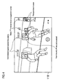
- Fig. 4 shows an example of an image displayed on the screen of the viewfinder 118 as a result of performing the face recognition auto-tracking mode. Shown in Fig. 4 is an image that is obtained when the auto-tracking is performed for a video of a soccer game, and face frames for recognized face images in the screen are indicated by, for example, light blue color.
- a title(s) (such as a name, number, or the like) is displayed in the vicinity of face frame(s) of face image of which pattern data is registered.
- face images of four persons are recognized, and two of them are the face images of the persons whose pattern data are registered.
- titles of those persons are displayed for the face images (face frame) as "XXXX#1" and "YYYY#2", respectively.
- titles for those face images are displayed as "#??", and the operator can see that those persons are not registered.
- information other than "#??", indicating non-registration may be displayed for a face image whose pattern data is not registered. Furthermore, by use of the predetermined switch, the operator can select as to whether or not the title is displayed. Thus, since it becomes slightly difficult to see the screen if the title display is activated as shown in Fig. 4 , the title display (which includes the information display indicating non-registration) may be inactivated so as to see the subjects more clearly.
- the face frame of the face image set as the tracking target, which is to be tracked as the AF target that is, the AF frame is indicated in, for example, light blue color, and the other face frames are indicated in yellow color.
- the used colors are not limited to thereto.
- a different method may be used to distinguish a face image that is set as the tracking target to be tracked as the AF target from the other face images.
- the face frame of the face image which is set as the tracking target to be tracked as the AF target, is not set as the AF frame, but an AF frame different from the face frame may be set in accordance with a position of the face frame of the face image, which is set as the tracking target to be tracked as the AF target, and may be displayed on the viewfinder 18.
- Fig. 5 is a block diagram showing another exemplary configuration of the imaging system to which the autofocus system according to the invention is applied.
- a tracking device 116 has the auto-tracking function as described in the flowchart of Figs. 3A and 3B , and a zoom and focus preset function.
- this tracking device corresponds to an aspect in which the auto-tracking function is provided in a device which is so-called a shot box having the preset function.
- the preset function is a function in which the zoom and focus positions of the lens device 12 are previously registered, and zoom and focus positions that are set to optional positions can be changed (reproduced) to the previously registered positions by the predetermined switch operation.
- the configuration for performing the preset function is omitted, but in an operation unit 114, the configuration for performing the preset function is shown.
- the operation unit 114 in the drawing includes: an arrow key 114a as an operation member for manually designating a moving direction and of an AF frame and a movement amount of the AF frame, instead of the track ball 14a; shot switches 114b for registering and reproducing preset positions of zooming (Z) and focusing (F) or registering and selecting tracking targets (person's face images); display panels 114c for checking registration of titles of the tracking targets; indicators 114d indicating the registered preset positions of the zooming (Z) and focusing (F); a slide switch 114e for switching a function (mode) of the tracking device 116; a memo switch 114f for giving an instruction for registering the preset positions and pattern data of a person's face; and the like.
- a preset function mode (Z + F mode) of zooming and focusing, a face recognition auto-tracking mode (OBJ mode), and a combination mode (Z + F + OBJ mode), and any of the three modes can be selected by changing a setting position of the slide switch 114e.
- the Z + F mode is a mode for reproducing the preset positions of zooming and focusing, which is a normal function of the shot box.
- the OBJ mode is a mode for automatically tracking a specific person's face image as the AF target by the process of the face recognition auto-tracking mode described in the first embodiment.
- the combination mode is a mode in which the Z + F mode and the OBJ mode are combined, and is a mode for reproducing the preset positions of zooming and focusing and for automatically tracking a specific person's face image as the AF target by the process of the face recognition auto-tracking mode.
- the Z + F mode may be a mode for reproducing any one of zooming and focusing at the preset position.
- step S500 it is determined as to whether or not the memo switch 114f is turned on (step S500). If the determination result is YES, it is further determined as to whether or not the slide switch 114e is set to the Z + F mode (step S502). Here, if the determination result is YES, the process for registering the preset positions of zooming and focusing is performed (step S504). That is, among the four shot switches 114b numbered by 1 to 4 in Fig. 5 , if an operator turns any one of the shot switches 114b on, the current zoom position and focus position of the lens device 12 are read by the tracking device 116, and the zoom position and the focus position are registered (stored) as preset positions corresponding to the on-state shot switch 114b.
- the registered preset positions are indicated by the indicator 114d, which corresponds to the shot switch 114b in which the preset positions are registered. Furthermore, the operator may not turn the shot switches 114b on, and the preset positions may be registered in association with the non-registration shot switches 114b in order from No. 1.
- the flow proceeds to step S520.
- step S502 determines whether or not the slide switch 114e is set to the OBJ mode.
- step S506 determines whether or not the slide switch 114e is set to the OBJ mode.
- step S508 the pattern registration process for registering pattern data of a specific person's face image is performed. That is, the processes shown in steps S114 to S 132 of the flowchart of Fig. 3A in the first embodiment are performed. At this time, it is possible to register pattern data of face images of different persons in the shot switches 114b of Nos. 1 to 4, respectively.
- step S508 the operator may turn on the shot switch 114b of the number to register in a similar manner to that in the Z + F mode, and the pattern data may be registered in the non-registration shot switches 114b in order from No. 1. Furthermore, a title for distinguishing identifying a person of which the pattern data can be registered by a character input device (not shown in the drawings), and the title is displayed on the display panel 114c corresponding to the registered shot switch 114b.
- step S506 If the determination result in step S506 is NO, the slide switch 114e is set to the Z + F + OBJ mode, and first, and the process for registering the preset positions of zooming and focusing is performed (step S510) in the same manner as step S504. Subsequently, the pattern registration process is performed (step S512) in a similar manner to step S508.
- the preset positions of zooming and focusing and the pattern data of the face image are registered. These data are registered in association with the shot switch having the number turned on by the operator when the preset positions are registered. However, the operator may not turn the shot switches 114b on, and the preset positions and the pattern data of the face image may be registered in association with the non-registration shot switches 114b in order from No. 1. Furthermore, the registered preset positions are displayed on the indicators 114d, and the title of the registered person is displayed on the display panel 114c. When the process of step S512 is completed, the flow proceeds to step S520.
- step S500 determines whether or not any one of the shot switches 114b is turned on (step S520).
- step S522 it is further determined as to whether or not the slide switch 114e is set to the Z + F mode (step S522).
- the determination result is YES, the process for reproducing (changing) the zooming and focusing of the lens device 12 to the preset positions, which is registered in association with the on-state shot switch (step S524).
- step S524 the process of the flowchart is completed, and the flow proceeds to another process.
- step S522 determines whether or not the slide switch 114e is set to the OBJ mode (step S526).
- the determination result is YES
- the process of the face recognition auto-tracking mode as shown in steps S136 to S174 of Fig. 3B is performed, and a face image that coincides with the pattern data, which is registered in association with the on-state shot switch, is set as a tracking target to be automatically tracked as the AF target (step S528).
- the AF process is performed (step S530). Further, in steps S136 to S174 of Fig.
- step S530 the process of the flowchart is completed, the flow proceeds to another process.
- step S526 the slide switch 114e is set to the Z + F + OBJ mode, and first, the process is performed in a similar manner to step S524, in which the zooming and focusing of the lens device 12 are reproduced (changed) to the preset positions, which are registered in association with the on-state shot switch (step S532). Subsequently, in a similar manner to step S528, the process of the face recognition auto-tracking mode is performed. Then, the face image coinciding with the pattern data, which is registered in association with the on-state shot switch, is set as a tracking target to be automatically tracked as the AF target (step S534). Then, in the lens device 12, the AF process is performed (step S536). When the process of step S536 is completed, the process of the flowchart is completed, and the flow advances to another process.
- the four shot switches 114b are provided (the registered number is four).
- the number of the shot switches 114b is not limited to four.
- the tracking device 116 of Fig. 5 can be used to select any of three modes of the Z + F mode, the OBJ mode, and the Z + F + OBJ mode by changing the setting position of the slide switch 114e.
- any of only two modes may be adapted to be selectable.
- the pattern data of the person's face image is registered, and in the face recognition auto-tracking mode, the registered face image is automatically tracked as the AF target.
- an object subject
Landscapes
- Engineering & Computer Science (AREA)
- Multimedia (AREA)
- Signal Processing (AREA)
- Automatic Focus Adjustment (AREA)
- Studio Devices (AREA)
- Collating Specific Patterns (AREA)
Applications Claiming Priority (4)
| Application Number | Priority Date | Filing Date | Title |
|---|---|---|---|
| JP2008072065A JP2009229569A (ja) | 2008-03-19 | 2008-03-19 | オートフォーカスシステム |
| JP2008072067A JP5027704B2 (ja) | 2008-03-19 | 2008-03-19 | オートフォーカスシステム |
| JP2008072066A JP2009229570A (ja) | 2008-03-19 | 2008-03-19 | オートフォーカスシステム |
| JP2008072064A JP2009229568A (ja) | 2008-03-19 | 2008-03-19 | オートフォーカスシステム |
Publications (2)
| Publication Number | Publication Date |
|---|---|
| EP2104338A2 true EP2104338A2 (fr) | 2009-09-23 |
| EP2104338A3 EP2104338A3 (fr) | 2011-08-31 |
Family
ID=40828010
Family Applications (1)
| Application Number | Title | Priority Date | Filing Date |
|---|---|---|---|
| EP09002038A Withdrawn EP2104338A3 (fr) | 2008-03-19 | 2009-02-13 | Système autofocus |
Country Status (2)
| Country | Link |
|---|---|
| US (1) | US8265474B2 (fr) |
| EP (1) | EP2104338A3 (fr) |
Cited By (5)
| Publication number | Priority date | Publication date | Assignee | Title |
|---|---|---|---|---|
| EP2339826A1 (fr) * | 2009-11-17 | 2011-06-29 | Fujifilm Corporation | Système autofocus |
| WO2012116347A1 (fr) * | 2011-02-24 | 2012-08-30 | Qualcomm Incorporated | Suivi à auto-focalisation |
| WO2013119420A1 (fr) * | 2012-02-06 | 2013-08-15 | Qualcomm Incorporated | Procédé et appareil de capture automatique d'une image |
| EP2355492A4 (fr) * | 2009-10-07 | 2013-12-04 | Panasonic Corp | Dispositif, procédé, programme, et circuit de sélection de sujet à suivre |
| US12126899B2 (en) | 2018-12-14 | 2024-10-22 | Sony Group Corporation | Imaging device, imaging control device, and imaging method |
Families Citing this family (20)
| Publication number | Priority date | Publication date | Assignee | Title |
|---|---|---|---|---|
| JP4478093B2 (ja) * | 2005-10-17 | 2010-06-09 | 富士フイルム株式会社 | 対象画像検索装置およびディジタル・カメラならびにそれらの制御方法 |
| US20090067805A1 (en) * | 2007-09-10 | 2009-03-12 | Victor Company Of Japan, Limited | Recording and reproducing device |
| EP2104339A3 (fr) * | 2008-03-19 | 2011-05-11 | Fujinon Corporation | Système autofocus |
| EP2104337A3 (fr) * | 2008-03-19 | 2011-04-27 | Fujinon Corporation | Système autofocus |
| US9269154B2 (en) * | 2009-01-13 | 2016-02-23 | Futurewei Technologies, Inc. | Method and system for image processing to classify an object in an image |
| JP5493789B2 (ja) | 2009-12-07 | 2014-05-14 | 株式会社リコー | 撮像装置および撮像方法 |
| US9104909B2 (en) * | 2010-12-15 | 2015-08-11 | Canon Kabushiki Kaisha | Image processing apparatus and method of processing image |
| US11195057B2 (en) | 2014-03-18 | 2021-12-07 | Z Advanced Computing, Inc. | System and method for extremely efficient image and pattern recognition and artificial intelligence platform |
| US11074495B2 (en) | 2013-02-28 | 2021-07-27 | Z Advanced Computing, Inc. (Zac) | System and method for extremely efficient image and pattern recognition and artificial intelligence platform |
| US9916538B2 (en) | 2012-09-15 | 2018-03-13 | Z Advanced Computing, Inc. | Method and system for feature detection |
| US8873813B2 (en) | 2012-09-17 | 2014-10-28 | Z Advanced Computing, Inc. | Application of Z-webs and Z-factors to analytics, search engine, learning, recognition, natural language, and other utilities |
| US11914674B2 (en) | 2011-09-24 | 2024-02-27 | Z Advanced Computing, Inc. | System and method for extremely efficient image and pattern recognition and artificial intelligence platform |
| KR20140102443A (ko) * | 2013-02-14 | 2014-08-22 | 삼성전자주식회사 | 카메라를 이용한 물체 추적 방법 및 이를 위한 카메라 시스템 |
| CN103197491B (zh) | 2013-03-28 | 2016-03-30 | 华为技术有限公司 | 快速自动聚焦的方法和图像采集装置 |
| JP2017102808A (ja) * | 2015-12-04 | 2017-06-08 | ソニー株式会社 | 画像処理装置および方法 |
| US10096125B1 (en) * | 2017-04-07 | 2018-10-09 | Adobe Systems Incorporated | Forecasting multiple poses based on a graphical image |
| CN107302666A (zh) * | 2017-08-29 | 2017-10-27 | 广东欧珀移动通信有限公司 | 拍照方法、移动终端及计算机可读存储介质 |
| CN110046548A (zh) * | 2019-03-08 | 2019-07-23 | 深圳神目信息技术有限公司 | 人脸的跟踪方法、装置、计算机设备和可读存储介质 |
| JP7425479B2 (ja) * | 2020-05-01 | 2024-01-31 | Awl株式会社 | サイネージ制御システム、及びサイネージ制御プログラム |
| US20260006309A1 (en) * | 2022-03-30 | 2026-01-01 | Sony Group Corporation | Imaging device, imaging control method, and program |
Citations (2)
| Publication number | Priority date | Publication date | Assignee | Title |
|---|---|---|---|---|
| US20060140612A1 (en) | 2004-12-28 | 2006-06-29 | Fujinon Corporation | Auto focus system |
| JP2006267221A (ja) | 2005-03-22 | 2006-10-05 | Fujinon Corp | オートフォーカスシステム |
Family Cites Families (27)
| Publication number | Priority date | Publication date | Assignee | Title |
|---|---|---|---|---|
| US5550928A (en) * | 1992-12-15 | 1996-08-27 | A.C. Nielsen Company | Audience measurement system and method |
| JPH098881A (ja) * | 1995-06-19 | 1997-01-10 | Sony Corp | 携帯電話機 |
| US6282362B1 (en) * | 1995-11-07 | 2001-08-28 | Trimble Navigation Limited | Geographical position/image digital recording and display system |
| US6940545B1 (en) * | 2000-02-28 | 2005-09-06 | Eastman Kodak Company | Face detecting camera and method |
| JP4590717B2 (ja) * | 2000-11-17 | 2010-12-01 | ソニー株式会社 | 顔識別装置及び顔識別方法 |
| JP2004053686A (ja) * | 2002-07-16 | 2004-02-19 | Olympus Corp | カメラ及び合焦装置の制御方法 |
| GB2395779A (en) * | 2002-11-29 | 2004-06-02 | Sony Uk Ltd | Face detection |
| US20040207743A1 (en) * | 2003-04-15 | 2004-10-21 | Nikon Corporation | Digital camera system |
| JP4196714B2 (ja) | 2003-04-15 | 2008-12-17 | 株式会社ニコン | デジタルカメラ |
| EP1630872B1 (fr) * | 2003-06-05 | 2016-12-28 | Mitsubishi Denki Kabushiki Kaisha | Dispositif a semi-conducteur et son procede de production |
| US7453506B2 (en) * | 2003-08-25 | 2008-11-18 | Fujifilm Corporation | Digital camera having a specified portion preview section |
| JP4525089B2 (ja) | 2004-01-27 | 2010-08-18 | フジノン株式会社 | オートフォーカスシステム |
| JP2005269604A (ja) * | 2004-02-20 | 2005-09-29 | Fuji Photo Film Co Ltd | 撮像装置、撮像方法、及び撮像プログラム |
| EP1601189A2 (fr) | 2004-05-26 | 2005-11-30 | Fujinon Corporation | Système de focalisation automatique |
| JP2005338352A (ja) | 2004-05-26 | 2005-12-08 | Fujinon Corp | オートフォーカスシステム |
| JP2006113265A (ja) * | 2004-10-14 | 2006-04-27 | Fujinon Corp | オートフォーカスシステム |
| JP2006115406A (ja) * | 2004-10-18 | 2006-04-27 | Omron Corp | 撮像装置 |
| JP2006119471A (ja) * | 2004-10-22 | 2006-05-11 | Fujinon Corp | オートフォーカスシステム |
| EP1659783A3 (fr) * | 2004-11-19 | 2006-05-31 | Fujinon Corporation | Appareil d'affichage de la zone AF et appareil de commande de la zone AF. |
| US7315631B1 (en) * | 2006-08-11 | 2008-01-01 | Fotonation Vision Limited | Real-time face tracking in a digital image acquisition device |
| JP2006258944A (ja) * | 2005-03-15 | 2006-09-28 | Fujinon Corp | オートフォーカスシステム |
| US7697827B2 (en) * | 2005-10-17 | 2010-04-13 | Konicek Jeffrey C | User-friendlier interfaces for a camera |
| JP2007248615A (ja) | 2006-03-14 | 2007-09-27 | Olympus Imaging Corp | カメラの焦点状態表示装置 |
| JP2007279601A (ja) | 2006-04-11 | 2007-10-25 | Nikon Corp | カメラ |
| JP4457358B2 (ja) | 2006-05-12 | 2010-04-28 | 富士フイルム株式会社 | 顔検出枠の表示方法、文字情報の表示方法及び撮像装置 |
| JP4264660B2 (ja) * | 2006-06-09 | 2009-05-20 | ソニー株式会社 | 撮像装置、および撮像装置制御方法、並びにコンピュータ・プログラム |
| US20080240503A1 (en) * | 2007-03-30 | 2008-10-02 | Sanyo Electric Co., Ltd. | Image Processing Apparatus And Image Pickup Apparatus Mounting The Same, And Image Processing Method |
-
2009
- 2009-02-13 EP EP09002038A patent/EP2104338A3/fr not_active Withdrawn
- 2009-02-13 US US12/370,922 patent/US8265474B2/en not_active Expired - Fee Related
Patent Citations (2)
| Publication number | Priority date | Publication date | Assignee | Title |
|---|---|---|---|---|
| US20060140612A1 (en) | 2004-12-28 | 2006-06-29 | Fujinon Corporation | Auto focus system |
| JP2006267221A (ja) | 2005-03-22 | 2006-10-05 | Fujinon Corp | オートフォーカスシステム |
Cited By (10)
| Publication number | Priority date | Publication date | Assignee | Title |
|---|---|---|---|---|
| EP2355492A4 (fr) * | 2009-10-07 | 2013-12-04 | Panasonic Corp | Dispositif, procédé, programme, et circuit de sélection de sujet à suivre |
| EP2339826A1 (fr) * | 2009-11-17 | 2011-06-29 | Fujifilm Corporation | Système autofocus |
| US8643766B2 (en) | 2009-11-17 | 2014-02-04 | Fujifilm Corporation | Autofocus system equipped with a face recognition and tracking function |
| WO2012116347A1 (fr) * | 2011-02-24 | 2012-08-30 | Qualcomm Incorporated | Suivi à auto-focalisation |
| CN103535021A (zh) * | 2011-02-24 | 2014-01-22 | 高通股份有限公司 | 自动对焦追踪 |
| US9077890B2 (en) | 2011-02-24 | 2015-07-07 | Qualcomm Incorporated | Auto-focus tracking |
| WO2013119420A1 (fr) * | 2012-02-06 | 2013-08-15 | Qualcomm Incorporated | Procédé et appareil de capture automatique d'une image |
| US9036069B2 (en) | 2012-02-06 | 2015-05-19 | Qualcomm Incorporated | Method and apparatus for unattended image capture |
| US9392163B2 (en) | 2012-02-06 | 2016-07-12 | Qualcomm Incorporated | Method and apparatus for unattended image capture |
| US12126899B2 (en) | 2018-12-14 | 2024-10-22 | Sony Group Corporation | Imaging device, imaging control device, and imaging method |
Also Published As
| Publication number | Publication date |
|---|---|
| EP2104338A3 (fr) | 2011-08-31 |
| US20090238549A1 (en) | 2009-09-24 |
| US8265474B2 (en) | 2012-09-11 |
Similar Documents
| Publication | Publication Date | Title |
|---|---|---|
| EP2104338A2 (fr) | Système autofocus | |
| EP2104339A2 (fr) | Système autofocus | |
| JP5830373B2 (ja) | 撮像装置 | |
| US9761010B2 (en) | Tracking apparatus | |
| US7978968B2 (en) | Auto focus device | |
| JP2005215040A (ja) | オートフォーカスシステム | |
| JP3970046B2 (ja) | カメラ | |
| US7860385B2 (en) | Autofocus system | |
| JP5384172B2 (ja) | オートフォーカスシステム | |
| EP3018891B1 (fr) | Dispositif de poursuite, procédé de poursuite, et support d'enregistrement non transitoire contenant un programme de poursuite | |
| WO2010073619A1 (fr) | Dispositif de capture d'image | |
| US20100123790A1 (en) | Autofocus system | |
| JP2006058431A (ja) | オートフォーカスシステム | |
| JP4596246B2 (ja) | オートフォーカスシステム | |
| JP4902577B2 (ja) | オートフォーカスシステム | |
| JP2010230871A (ja) | オートフォーカスシステム | |
| JP5027704B2 (ja) | オートフォーカスシステム | |
| US11669975B2 (en) | Subject tracking device, subject tracking method, and imaging apparatus | |
| JP2008148089A (ja) | 投影装置およびカメラ | |
| JP2009229568A (ja) | オートフォーカスシステム | |
| JP2009229570A (ja) | オートフォーカスシステム | |
| JP2009229588A (ja) | オートフォーカスシステム | |
| JP2009186914A (ja) | 焦点検出装置および焦点調節装置ならびに撮像装置 | |
| JP5048559B2 (ja) | オートフォーカスシステム | |
| JP5965653B2 (ja) | 追尾装置及び追尾方法 |
Legal Events
| Date | Code | Title | Description |
|---|---|---|---|
| PUAI | Public reference made under article 153(3) epc to a published international application that has entered the european phase |
Free format text: ORIGINAL CODE: 0009012 |
|
| 17P | Request for examination filed |
Effective date: 20090213 |
|
| AK | Designated contracting states |
Kind code of ref document: A2 Designated state(s): AT BE BG CH CY CZ DE DK EE ES FI FR GB GR HR HU IE IS IT LI LT LU LV MC MK MT NL NO PL PT RO SE SI SK TR |
|
| AX | Request for extension of the european patent |
Extension state: AL BA RS |
|
| PUAL | Search report despatched |
Free format text: ORIGINAL CODE: 0009013 |
|
| AK | Designated contracting states |
Kind code of ref document: A3 Designated state(s): AT BE BG CH CY CZ DE DK EE ES FI FR GB GR HR HU IE IS IT LI LT LU LV MC MK MT NL NO PL PT RO SE SI SK TR |
|
| AX | Request for extension of the european patent |
Extension state: AL BA RS |
|
| RAP1 | Party data changed (applicant data changed or rights of an application transferred) |
Owner name: FUJIFILM CORPORATION |
|
| RIC1 | Information provided on ipc code assigned before grant |
Ipc: H04N 5/232 20060101AFI20110722BHEP |
|
| AKX | Designation fees paid |
Designated state(s): AT BE BG CH CY CZ DE DK EE ES FI FR GB GR HR HU IE IS IT LI LT LU LV MC MK MT NL NO PL PT RO SE SI SK TR |
|
| STAA | Information on the status of an ep patent application or granted ep patent |
Free format text: STATUS: THE APPLICATION IS DEEMED TO BE WITHDRAWN |
|
| 18D | Application deemed to be withdrawn |
Effective date: 20120301 |