EP2104832B1 - Procédé et dispositif de détermination de la section de sortie d'un composant d'une turbine à gaz - Google Patents
Procédé et dispositif de détermination de la section de sortie d'un composant d'une turbine à gaz Download PDFInfo
- Publication number
- EP2104832B1 EP2104832B1 EP07856093A EP07856093A EP2104832B1 EP 2104832 B1 EP2104832 B1 EP 2104832B1 EP 07856093 A EP07856093 A EP 07856093A EP 07856093 A EP07856093 A EP 07856093A EP 2104832 B1 EP2104832 B1 EP 2104832B1
- Authority
- EP
- European Patent Office
- Prior art keywords
- outlet cross
- section
- component
- measuring
- turbine
- Prior art date
- Legal status (The legal status is an assumption and is not a legal conclusion. Google has not performed a legal analysis and makes no representation as to the accuracy of the status listed.)
- Not-in-force
Links
Images

Classifications
-
- G—PHYSICS
- G01—MEASURING; TESTING
- G01B—MEASURING LENGTH, THICKNESS OR SIMILAR LINEAR DIMENSIONS; MEASURING ANGLES; MEASURING AREAS; MEASURING IRREGULARITIES OF SURFACES OR CONTOURS
- G01B5/00—Measuring arrangements characterised by the use of mechanical techniques
- G01B5/14—Measuring arrangements characterised by the use of mechanical techniques for measuring distance or clearance between spaced objects or spaced apertures
-
- F—MECHANICAL ENGINEERING; LIGHTING; HEATING; WEAPONS; BLASTING
- F01—MACHINES OR ENGINES IN GENERAL; ENGINE PLANTS IN GENERAL; STEAM ENGINES
- F01D—NON-POSITIVE DISPLACEMENT MACHINES OR ENGINES, e.g. STEAM TURBINES
- F01D21/00—Shutting-down of machines or engines, e.g. in emergency; Regulating, controlling, or safety means not otherwise provided for
- F01D21/003—Arrangements for testing or measuring
-
- G—PHYSICS
- G01—MEASURING; TESTING
- G01B—MEASURING LENGTH, THICKNESS OR SIMILAR LINEAR DIMENSIONS; MEASURING ANGLES; MEASURING AREAS; MEASURING IRREGULARITIES OF SURFACES OR CONTOURS
- G01B5/00—Measuring arrangements characterised by the use of mechanical techniques
- G01B5/20—Measuring arrangements characterised by the use of mechanical techniques for measuring contours or curvatures
- G01B5/205—Measuring arrangements characterised by the use of mechanical techniques for measuring contours or curvatures of turbine blades or propellers
-
- G—PHYSICS
- G01—MEASURING; TESTING
- G01B—MEASURING LENGTH, THICKNESS OR SIMILAR LINEAR DIMENSIONS; MEASURING ANGLES; MEASURING AREAS; MEASURING IRREGULARITIES OF SURFACES OR CONTOURS
- G01B5/00—Measuring arrangements characterised by the use of mechanical techniques
- G01B5/26—Measuring arrangements characterised by the use of mechanical techniques for measuring areas, e.g. planimeters
Definitions
- the invention relates to a method and a device for determining the outlet cross section of a, one or more turbine blades comprising component, in particular a turbine blade twin, a gas turbine of the type specified in the preambles of claims 1 and 10 respectively.
- An essential factor of engine performance is the outlet cross section or the narrowest cross section of the turbine blades acting as nozzles.
- the area of this exit cross-section is affected by the wear of the turbine blades and must be corrected accordingly from time to time, for example by a local application of material to the turbine blades.
- the outlet cross section or the narrowest cross section between two turbine blades is measured from the concave side of the one turbine blade to the convex side of the adjacent turbine blade.
- the outlet cross section runs in a plane which runs perpendicular to the outflow direction and at the level of the outlet edge of the respective turbine blade.
- the outflow direction or the exit angle arise as a tangent of the concave side of the respective turbine blade at its trailing edge.
- each component Since each component is measured separately for itself, it has hitherto proven to be extremely problematic to measure the respective outlet cross sections of each of the components with high reproducibility or repeatability. This is currently done by means of a mechanical dial gauge with which pointwise measured values are recorded in the region of the respective outlet cross section. For example, radii of the outlet cross section are ignored. Another problem so far is the measurement of the open outlet cross-sections, since these have no corresponding boundary wall to the respectively associated end face of the component.
- US-A-4,896,430 describes a device for measuring the outlet cross section between two turbine blades.
- the device has a linearly displaceable measuring head with two sensors, the movement of which is measured perpendicular to the direction of displacement.
- the measuring device moves the measuring head from the inner to the outer end of the outlet cross section, wherein the width of the outlet cross section is measured and calculated in a computer unit, the outlet cross section itself.
- GB-A-2 058 373 describes a device for measuring two open outlet cross-sections laterally of a turbine blade in a component.
- the component is held by means of a holding device which has two reference surfaces at the desired positions of the adjoining turbine blades.
- the outlet cross section can be measured on both sides of the turbine blade.
- Object of the present invention is therefore to provide a method and an apparatus of the type mentioned, with which the respective outlet cross sections of the component can be measured more accurately and with higher reproducibility.
- the respective boundary walls of the associated outlet cross section are scanned or scanned along a measuring line by means of the measuring device.
- the respective boundary walls of the associated outlet cross section are scanned or scanned along a continuous measuring line with the measuring device, for example by means of a probe head.
- a measurement interval can be determined in a simple manner, in which associated measured values are recorded by the computer unit when the measurement line is being traveled or scanned. Accordingly, it can be determined by means of the computer unit at which times or at which points of the measuring line a measured value is to be recorded which serves for calculating the area of the outlet cross section. By specifying the measurement interval, it is also possible to regulate the accuracy or the reproducibility of the measurement method.
- one of the open outlet cross-sections is to be measured laterally of the respectively associated turbine blade, then it has proven to be particularly effective to guide the measuring device or its probe along the boundary walls in an open measuring line between starting and ending points which are remote from one another.
- the start and end points of the measurement line are selected in the area of the respective face of the component.
- the plane at the respective front side of the component can be determined in a simple manner by determining a plurality of respective measuring points in the region of the end faces of an inner and outer platform of the component, wherein the corresponding plane can be determined by the arithmetic unit by the measuring points , Since, on the one hand, a respective plane is determined on the end face of the component and, on the other hand, the associated open outlet cross section is traversed by means of the open measuring line, the computer unit can thus determine the boundary line of the open outlet cross section to the open side of the component in an extremely accurate and reproducible manner. Like the extremely precisely determinable boundary line, the area of the open outlet cross section can be determined correspondingly accurately or reproducibly.
- the measuring points in the region of the respective end face of the inner and outer platform of the component are determined before the respective associated open measuring line of the corresponding open outlet cross section is scanned or scanned. Since thus already the plane is fixed to the front side of the component before the associated open If the measuring line is traversed, its start and end points or a first and a last measuring point can be determined extremely accurately.
- the measuring device for determining the respective measuring line and / or for determining the plurality of measuring points in the region of the front side is moved by hand along the component. This makes it possible to ensure a sufficiently fast measuring method, whereby it is ensured by the corresponding stops of the holding device that the movement of the measuring device by hand takes place with sufficient accuracy.
- the two open outlet cross sections are summed up to form an entire outlet cross section, which corresponds in size at least approximately to that of the closed outlet cross section.
- the one value results from that of the closed outlet cross-section between the two turbine blades, and the other value results from the sum of the two open outlet cross-sections laterally of the respective turbine blade.
- the total exit area of a turbine bucket ring can be determined by summing the respective exit cross sections of each turbine bucket twin.
- the device according to the invention comprises a holding device, within which the component can be fixed for the reproducible determination of the respective outlet cross sections.
- the holding device comprises at least one stop which runs perpendicular to an associated exit angle and extends in the plane of the respective outlet cross section. By such a stop, it is possible to drive the measuring device or its probe extremely accurate and reproducible by hand along the boundary walls of the respective outlet cross-section.
- the holding device for each of the outlet cross-sections of the component has a stop, so that in a sequence all outlet cross-sections - for example by hand - extremely accurate and reproducible along the respective associated open or closed measurement line can be.
- the measuring device is to be calibrated by means of a calibration component and / or a calibration cone. This ensures in a simple manner that the measurement of the respective components or of their respective outlet cross sections can be carried out without significant measurement errors.
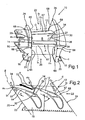
- Fig. 1 and 2 is shown in a schematic perspective view and in a schematic sectional view of a component of a gas turbine in the form of a turbine blade twin 10, which is formed in its basic form approximately circular segment.
- a turbine blade twin 10 which is formed in its basic form approximately circular segment.
- three and twenty such turbine blade twins 10 can be combined to form a turbine blade ring, which can be arranged in the high-pressure turbine part of a jet engine.
- This turbine blade ring also referred to as a Vane ring, is fixedly disposed within the high pressure turbine section, whereby its turbine blades act as vanes.
- the present turbine blade twin 10 comprises two turbine blades 12, 14, which in FIG Fig. 2 can be seen on average.
- the two turbine blades 12, 14 extend between a radially inner platform 16 and a radially outer platform 18.
- the inner platform 16 terminates at respective end faces 24, 25 and the outer platform 18th ends at respective end faces 26, 27.
- all four end faces 22, 24, 25, 26 extend at an identical angle of inclination a.
- the mutually associated end faces 23 and 25 or 24 and 26 are arranged or aligned so that overall the annular segment-shaped base contour of the turbine blade twin 10 results.
- discharge cross section This is also referred to as the narrowest cross-section or as a "throat area" of the guide vanes 12, 14 acting as nozzles. This must be within certain limits according to the engine manufacturer's repair and assembly instructions. Therefore, it is necessary that this outlet cross-section can be measured as accurately as possible.
- a closed outlet cross-section B is first explained, which is bounded by corresponding boundary walls 27, 28 on the concave or convex side of the turbine blades 12, 14 or by boundary walls 29, 30 of the inner and outer platforms 16, 18 on the outer peripheral side.
- This closed outlet cross-section B extends from the concave side of the one turbine blade 12 to the convex side of the adjacent turbine blade 14 in a plane which is perpendicular to the outflow direction or the corresponding exit angle shown in arrow 32 at the exit edge 34 of the turbine blade 12.
- the outflow direction represented by the arrow 32 results as a tangent T of the concave side of the turbine blade 12 at the exit edge 34.
- the closed outlet cross-section B there are two open outlet cross-sections A, C in the turbine blade twin 10, which each extend laterally of the associated turbine blade 12, 14 toward the respective front side 20, 22 of the turbine blade twin 10.
- These respective open outlet cross-sections A, C are each completed by an entire or closed outlet cross-section A, C, that an adjacent turbine blade twin 10 is attached to the respective turbine blade twin 10.
- all turbine blade twins 10 are of identical shape, this idea is exploited to the effect that the two open outlet cross-sections A, C complete to form an entire outlet cross-section, which then at least approximately corresponds to the area of the closed outlet cross-section B.
- each turbine blade twin 10 is measured by itself, not only the closed outlet cross-section B between the two turbine blades 12, 14 must be determined, but also the two open ones Outlet cross-sections A, C, which then also complete in total to a total outlet cross-section.
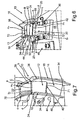
- a holding device 36 of a device is shown in a schematic perspective view, with which the three outlet cross-sections A, B, C can be determined.
- the holding device 36 comprises three receptacles 38, 40, 42, between which the two turbine blades 12, 14 can be positioned.
- the turbine blade twin 10 can be positioned on the holding device 36 such that the central receptacle 40 projects into the intermediate space between the two turbine blades 12, 14.
- the rear receptacle 38 thus comes into abutment with the convex side of the turbine blade 12, while the front receptacle 42 comes into abutment with the concave side of the turbine blade 14.
- the three receptacles 38, 40, 42 are adjustable relative to each other so that a positionally accurate fixation of the turbine blade twin 10 to the holding device 36 can be realized.
- the surfaces of the receptacles 38, 40, 42 coming into contact with the turbine blades 12, 14 are correspondingly adapted to their concave or convex sides.
- the central receptacle 40 is adapted both to the convex side of the turbine blade 14 and to the concave side of the turbine blade 12.
- the turbine blade twin 10 is fixed relative to the receptacles 38, 40, 42, this is held down by means of a top plate 44 to the holding device 36.
- the upper plate 44 can be fixed to a lower part 46, which in turn rests together with the holding device 36 on a base plate 48.
- the top plate 44 is supported against a collar 50 of the inner platform 16 of the turbine blade twin 10.
- Fig. 4 is shown in a schematic and perspective side view of a measuring device 52, which is presently designed as a multi-jointed measuring arm.
- the Measuring device 52 includes a base part 54, by means of which it can be arranged on the base plate 48.
- the measuring device 52 comprises a probe 56, by means of which the turbine blade twin 10 or in particular its outlet cross-sections A, B, C can be measured in a manner to be described in more detail below.
- the measuring device 52 is connected, for example via a line 58 with a computer unit 60 only schematically indicated, which serves to determine the individual outlet cross-sections A, B, C in a manner to be described in more detail below.
- a calibration cone 62 can be seen, which can be fixed on the base plate 48.
- the calibration cone 62 comprises three measuring points 64, via which the measuring device 52 can be calibrated.
- a calibration of the holding device 36 can be carried out by fixing a calibration component corresponding to the shape of the turbine blade twin 10 to the latter.
- the positions of the outlet cross sections A, B, C in particular can be calibrated relative to the measuring device 52.
- an open, U-shaped measuring line m 1 is scanned or scanned along the respective boundary walls 65, 66, 67 of the open outlet cross section A by means of the measuring device 52 or by means of its probe 56.
- the probe 56 is guided from a starting point 68 to an end point 69 in a closed line.
- the probe 46 is guided along a flat stop 72, which is formed by the end face of the front receptacle 42 of the holding device 36. In other words, the front end of the front receptacle 42 is formed so that it is perpendicular to the exit angle or in the plane of the outlet cross-section A.
- the probe head 56 can be guided to move the measuring line m 1 in the corner region between the stop 72 and the respective boundary walls 65, 66, 67 of the open outlet cross-section A.
- the starting point 68 and the end point 69 of the open measuring line m 1 are located at the respective end face 23, 25 of the associated platform 16, 18.
- associated measured values are recorded when the measuring line m 1 is traveled.
- the plane E determined by the computer unit 60 which is determined by the measuring points a, b, c, d, and the area of the outlet cross-section A, which is determined by the measuring line m 1 , intersect in the region of a boundary line b 1 .
- the boundary line b 1 results from the intersection of the plane of the open outlet cross-section A and the plane E, which is determined by the measuring points a, b, c, d. Consequently, the line-shaped end of the open outlet cross-section A can be determined unambiguously by the boundary line b 1 , so that the area of the outlet cross-section A can be uniquely determined or specified.
- Both the determination of the plane E and of the outlet cross-section A are carried out here by means of the arithmetic unit 60.
- the outer peripheral-side boundary walls 27, 28, 29, 30 are scanned or scanned along a circumferential measuring line m 2 by means of the probe 56.
- This measuring line m 2 is in turn in the plane of the outlet cross section B.
- This level is determined by a stop 71, which is formed by the front end side of the central receptacle 40.
- the front end of the receptacle 40 is formed or arranged so that it lies exactly in the plane of the closed outlet cross-section B.
- the closed measuring line m 2 can thus be traversed in a simple manner by means of the probe 56, that this is guided in the corner region between the stop 71 and the boundary walls 27, 28, 29, 30 along a closed circumferential line.
- a plurality of measured values are recorded by means of the arithmetic unit 60, wherein the measuring intervals are optionally adjustable.
- the U-shaped open measuring line m 3 can now again be scanned or scanned along the respective boundary walls 65, 66, 67 of the outlet cross-section C, the starting point 68 again in the region of the one end point 69 in the region of the other end side 24, 26 is selected.
- the end face of the receptacle 38 serves as a stop 70, which runs in the plane of the outlet cross-section C. Consequently, in turn, the probe 56 can be moved in the corner region between the stop 70 and the boundary walls 65, 66, 67 along the measuring line m 3 .
- the boundary line b 3 again indicates the line-shaped end of the surface of the outlet cross-section C.
- the device 52 or its probe 56 are presently guided by hand along the measurement lines m 1 , m 2 , m 3 . Also by hand, the measuring points a, b, c, d of the two levels E are determined. However, it is to be considered within the scope of the invention that the probe head 56 could possibly also be automatically guided.
- the associated measuring lines m 1 , m 2 , m 3 can be traversed by the probes 56, 71, 72 in a relatively rapid sequence.
- the measurement points a, b, c, d which are respectively taken before the determination of the measurement lines m 1 and m 3 can likewise be made extremely fast, so that overall a method is provided in which the turbine blade twin 10 is in a time interval of less than 30 Measure seconds or the Ausschnittequerterrorisme a, b, c can be determined by means of the computer unit 60.
- the data output can be done by means of the computer unit 60 in a simple manner for each simple component 10 or for the complete turbine blade ring.
Landscapes
- Physics & Mathematics (AREA)
- General Physics & Mathematics (AREA)
- Engineering & Computer Science (AREA)
- Mechanical Engineering (AREA)
- General Engineering & Computer Science (AREA)
- Turbine Rotor Nozzle Sealing (AREA)
- Control Of Turbines (AREA)
- Length Measuring Devices With Unspecified Measuring Means (AREA)
Claims (13)
- Procédé destiné à déterminer la section de sortie (A, B, C) d'un composant, en particulier d'un système jumelé d'aubes de turbine (10), muni d'une ou de plusieurs aubes de turbine (12, 14), d'une turbine à gaz, dans lequel procédé au moins une section de sortie (B) fermée est mesurée entre les aubes de turbine (12, 14) respectives et/ou les sections de sortie (A, C) ouvertes respectives, latéralement de ladite au moins une aube de turbine (12, 14) au moyen d'un dispositif de mesure (52), sachant que pour déterminer la section de sortie (A, B, C) correspondante, le dispositif de mesure (52) passe sur les parois de délimitation (27, 28, 29, 30 ; 65, 66, 67) respectives de ladite section de sortie le long d'une ligne de mesure (m1, m2, m3) fermée sur le pourtour et/ou d'une ligne de mesure ouverte, des valeurs de mesure correspondantes étant enregistrées au moyen d'un ordinateur (60) pendant le passage sur la ligne de mesure (m1, m2, m3), et le composant (10) étant immobilisé par un dispositif de fixation (36) avant la détermination de la ligne de mesure (m1, m2, m3), caractérisé en ce que le plan de la section de sortie (A, B, C) respective est prédéfini au moyen d'une butée (70, 71, 72) associée du dispositif de fixation (36).
- Procédé selon la revendication 1, caractérisé en ce qu'un intervalle de mesure est déterminé, pendant lequel des valeurs de mesure associées sont enregistrées au moyen de l'ordinateur (60), pendant le passage sur la ligne de mesure (m1, m2, m3).
- section de sortie selon la revendication 1 ou 2, caractérisé en ce que pour déterminer la section de sortie (B) fermée, les parois de délimitation (27, 28, 29, 30) de celle-ci du côté du pourtour extérieur sont parcourues le long d'une ligne de mesure (m2) au pourtour fermé.
- Procédé selon l'une quelconque des revendications précédentes, caractérisé en ce que pour déterminer les sections de sortie (A, C) ouvertes, les parois de délimitation (65, 66, 67) de celles-ci sont parcourues le long d'une ligne de mesure (m1, m3) ouverte entre des points de départ et de fin (68, 69) de la ligne de mesure (m1, m3).
- Procédé selon la revendication 4, caractérisé en ce que pour déterminer les sections de sortie (A, C) ouvertes, un plan (E) respectif est déterminé sur les faces frontales (20, 22) du composant (10) au moyen de l'ordinateur (60), lequel détermine une ligne de délimitation (b1, b3) respective de la section de sortie (A, C) ouverte respectivement associée.
- Procédé selon la revendication 5, caractérisé en ce que les plans (E) sont déterminés par une pluralité de points de mesure (a, b, c, d), déterminés par le dispositif de mesure (52), dans la zone des faces frontales (23, 24, 25, 26) d'une plate-forme (16, 18) intérieure et extérieure du composant (10), reliant respectivement les aubes de turbine (12, 14) dans le sens périphérique.
- Procédé selon la revendication 6, caractérisé en ce que les points de mesure (a, b, c, d) sont déterminés dans la zone des faces frontales (23, 24, 25, 26) respectives de la plate-forme (16, 18) intérieure et extérieure du composant (10) avant le passage sur la ligne de mesure (m1, m3) ouverte respectivement associée de la section de sortie (A, C) ouverte correspondante.
- Procédé selon la revendication 6 ou 7, caractérisé en ce que le dispositif de mesure (52), destiné à mesurer la ligne de mesure (m1, m2, m3) respective et/ou destiné à déterminer la pluralité de points de mesure (a, b, c, d) dans la zone des faces frontales (23, 24, 25, 26) des plates-formes (16, 18), est déplacé manuellement le long du composant (10).
- Procédé selon l'une quelconque des revendications précédentes, caractérisé en ce que les deux sections de sortie (A, C) ouvertes sont additionnées pour former une section de sortie totale, à la suite de quoi est effectuée une addition avec ladite au moins une section de sortie (B) fermée.
- Dispositif destiné à déterminer la section de sortie (A, B, C) d'un composant, en particulier d'un système jumelé d'aubes de turbine (10), muni d'une ou de plusieurs aubes de turbine (12, 14), d'une turbine à gaz, comportant un dispositif de mesure (52), qui permet de mesurer au moins une section de sortie (B) fermée entre les aubes de turbine (12, 14) respectives et/ou les sections de sortie (A, C) ouvertes respectives, latéralement de ladite au moins une aube de turbine (12, 14), le dispositif de mesure (52) pouvant passer sur les parois de délimitation (27, 28, 29, 30 ; 65, 66, 67) de la section de sortie (A, B, C) concernée le long d'une ligne de mesure (m1, m2, m3), laquelle peut être analysée par un ordinateur (60), et sachant que pour l'immobilisation du composant (10), il est prévu un dispositif de fixation (36), le long duquel peut être guidé un dispositif de mesure (52), caractérisé en ce que le dispositif de fixation (36) comporte au moins une butée (70, 71, 72), qui est orientée perpendiculairement à un angle de sortie associé et qui s'étend dans le plan de la section de sortie (A, B, C) respective.
- Dispositif selon la revendication 10, caractérisé en ce que le dispositif de mesure (52) permet de déterminer une pluralité de points de mesure (a, b, c, d) d'un plan (E) associé sur les faces frontales (23, 24, 25, 26) d'une plate-forme (16, 18) intérieure et extérieure du composant (10), reliant respectivement les aubes de turbine (12, 14) dans le sens périphérique, l'ordinateur (60) permettant de déterminer une ligne de délimitation (b1, b3) respective de la section de sortie (A, C) ouverte respectivement associée.
- Dispositif selon la revendication 10 ou 11, caractérisé en ce que le dispositif de fixation (36) comporte pour chaque section de sortie (A, B, C) du composant (70, 71, 72) une butée (70, 71, 72) séparée.
- Dispositif selon l'une quelconque des revendications 10 à 12, caractérisé en ce que le dispositif de mesure (52) et le dispositif de fixation (36) doivent être calibrés au moyen d'un cône de calibrage (62) ou d'un élément de calibrage (10).
Applications Claiming Priority (2)
| Application Number | Priority Date | Filing Date | Title |
|---|---|---|---|
| DE102006061446A DE102006061446A1 (de) | 2006-12-23 | 2006-12-23 | Verfahren und Vorrichtung zur Ermittlung des Austrittsquerschnitts eines Bauteils einer Gasturbine |
| PCT/DE2007/002243 WO2008077373A1 (fr) | 2006-12-23 | 2007-12-12 | Procédé et dispositif de détermination de la section de sortie d'un composant d'une turbine à gaz |
Publications (2)
| Publication Number | Publication Date |
|---|---|
| EP2104832A1 EP2104832A1 (fr) | 2009-09-30 |
| EP2104832B1 true EP2104832B1 (fr) | 2010-05-05 |
Family
ID=39267795
Family Applications (1)
| Application Number | Title | Priority Date | Filing Date |
|---|---|---|---|
| EP07856093A Not-in-force EP2104832B1 (fr) | 2006-12-23 | 2007-12-12 | Procédé et dispositif de détermination de la section de sortie d'un composant d'une turbine à gaz |
Country Status (5)
| Country | Link |
|---|---|
| US (1) | US8694281B2 (fr) |
| EP (1) | EP2104832B1 (fr) |
| AT (1) | ATE467096T1 (fr) |
| DE (2) | DE102006061446A1 (fr) |
| WO (1) | WO2008077373A1 (fr) |
Families Citing this family (4)
| Publication number | Priority date | Publication date | Assignee | Title |
|---|---|---|---|---|
| US7898850B2 (en) | 2007-10-12 | 2011-03-01 | Micron Technology, Inc. | Memory cells, electronic systems, methods of forming memory cells, and methods of programming memory cells |
| CN102478396B (zh) * | 2010-11-30 | 2013-10-23 | 沈阳黎明航空发动机(集团)有限责任公司 | 一种整体叶盘叶片的形位尺寸测量方法及工具 |
| US8931184B1 (en) | 2012-05-21 | 2015-01-13 | General Electric Company | Method for dimensionally inspecting a component of a gas turbine system |
| JP6332740B2 (ja) * | 2014-03-13 | 2018-05-30 | 三菱日立パワーシステムズ株式会社 | 角度計測方法、測定治具 |
Family Cites Families (4)
| Publication number | Priority date | Publication date | Assignee | Title |
|---|---|---|---|---|
| US4327495A (en) * | 1979-09-18 | 1982-05-04 | The L. S. Starrett Company | Vane airfoil method and apparatus |
| US4896430A (en) * | 1988-10-27 | 1990-01-30 | Compair, Inc. | Scanning method and apparatus for measuring open flow area |
| US6604285B2 (en) * | 2001-06-07 | 2003-08-12 | General Electric Company | Method and apparatus for electronically determining nozzle throat area and harmonics |
| US20070050172A1 (en) * | 2005-09-01 | 2007-03-01 | General Electric Company | Method and apparatus for measuring throat areas of gas turbine engine nozzle assemblies |
-
2006
- 2006-12-23 DE DE102006061446A patent/DE102006061446A1/de not_active Withdrawn
-
2007
- 2007-12-12 EP EP07856093A patent/EP2104832B1/fr not_active Not-in-force
- 2007-12-12 US US12/520,952 patent/US8694281B2/en active Active
- 2007-12-12 DE DE502007003681T patent/DE502007003681D1/de active Active
- 2007-12-12 WO PCT/DE2007/002243 patent/WO2008077373A1/fr not_active Ceased
- 2007-12-12 AT AT07856093T patent/ATE467096T1/de active
Also Published As
| Publication number | Publication date |
|---|---|
| WO2008077373A1 (fr) | 2008-07-03 |
| DE102006061446A1 (de) | 2008-06-26 |
| DE502007003681D1 (de) | 2010-06-17 |
| US20100030514A1 (en) | 2010-02-04 |
| US8694281B2 (en) | 2014-04-08 |
| EP2104832A1 (fr) | 2009-09-30 |
| ATE467096T1 (de) | 2010-05-15 |
Similar Documents
| Publication | Publication Date | Title |
|---|---|---|
| EP2104832B1 (fr) | Procédé et dispositif de détermination de la section de sortie d'un composant d'une turbine à gaz | |
| EP3596426A1 (fr) | Procédé et dispositif pour déterminer, au moins sur certaines parties, de préférence complètement, la géométrie extérieure et intérieure d'une pièce comportant au moins une cavité | |
| DE60000908T2 (de) | Verbesserte präzisionsbiegepresse | |
| WO2011026974A1 (fr) | Dispositif de contrôle, appareil de contrôle et procédé de contrôle de rainures profilées | |
| DE2721281C2 (fr) | ||
| DE3340812A1 (de) | Vorrichtung zum aufnehmen eines gegenstandes und verfahren zum vermessen desselben | |
| DE2064075C3 (de) | Lehre zum Prüfen bzw. Messen der Verwindungslage von Turbinenschaufel-Stirnteilen | |
| EP3255373B1 (fr) | Mesure de contact au niveau du flanc d'une dent d'une roue dentée | |
| DE102021105918A1 (de) | Additives Reparatursystem | |
| DE2029544A1 (de) | Prüfvorrichtung fur gewölbte Schaufeln | |
| EP1716315B1 (fr) | Procede de fabrication de surfaces adaptees relevant de la technique des fluides | |
| EP1924391B1 (fr) | Procede de production d'alesages | |
| EP1825216A1 (fr) | Dispositif pour mesurer des pieces au moyen de capteurs a triangulation et unite d'evaluation | |
| EP3537102B1 (fr) | Procédé et dispositif d'augmentation du rendement pour une précision suffisante lors de la mesure de pièces à usiner | |
| EP2470858B1 (fr) | Procédé et dispositif de contrôle de qualité d'un élément en matière thermoplastique renforcé par fibres, façonné | |
| DE102019114892A1 (de) | Raunormal und Verfahren zur Kalibrierung und/oder Überprüfung eines Rauheitstastsystems einer Verzahnungsmaschine, Verzahnungsmesssystem und Referenzelement | |
| DE2101012A1 (de) | Meß- und Prüfvorrichtung | |
| DE3320983A1 (de) | Transportables geraet zur pruefung des zahnflankenprofils und der zahnflankenlinien (zahnschraege) von zahnraedern auf verzahnmaschinen oder zahnflankenschleifmaschinen sowie zur positionierung dieses geraetes und zum orientieren des messtasters an der verzahnung fuer den messvorgang | |
| EP1850089B1 (fr) | Dispositif et procédé destinés à la mesure spatiale de pièces à usiner sur une machine-outil | |
| DE2416120A1 (de) | Verfahren zum ausmessen von geometrischen parametern mechanischer werkstuecke | |
| EP3263839A1 (fr) | Procédé d'optimisation d'un design d'une aube et aube associée | |
| DE2317210A1 (de) | Vorrichtung zur geometrischen messung von oberflaechenprofilen, insbesondere von turbinenschaufeln und dergleichen | |
| DE10002684A1 (de) | Verfahren zur Ermittlung von Umform-Kenngrössen an Blechformteilen | |
| DE102009019920A1 (de) | Verfahren zur Bestimmung einer axialen Position einer Schaufel eines Rotors sowie eine Messvorrichtung zur Bestimmung von Schwingungen einer Schaufel eines Rotors | |
| EP4450197B1 (fr) | Procédé de mesure de denture |
Legal Events
| Date | Code | Title | Description |
|---|---|---|---|
| PUAI | Public reference made under article 153(3) epc to a published international application that has entered the european phase |
Free format text: ORIGINAL CODE: 0009012 |
|
| 17P | Request for examination filed |
Effective date: 20090722 |
|
| AK | Designated contracting states |
Kind code of ref document: A1 Designated state(s): AT BE BG CH CY CZ DE DK EE ES FI FR GB GR HU IE IS IT LI LT LU LV MC MT NL PL PT RO SE SI SK TR |
|
| GRAP | Despatch of communication of intention to grant a patent |
Free format text: ORIGINAL CODE: EPIDOSNIGR1 |
|
| DAX | Request for extension of the european patent (deleted) | ||
| GRAS | Grant fee paid |
Free format text: ORIGINAL CODE: EPIDOSNIGR3 |
|
| GRAA | (expected) grant |
Free format text: ORIGINAL CODE: 0009210 |
|
| AK | Designated contracting states |
Kind code of ref document: B1 Designated state(s): AT BE BG CH CY CZ DE DK EE ES FI FR GB GR HU IE IS IT LI LT LU LV MC MT NL PL PT RO SE SI SK TR |
|
| REG | Reference to a national code |
Ref country code: GB Ref legal event code: FG4D Free format text: NOT ENGLISH |
|
| REG | Reference to a national code |
Ref country code: CH Ref legal event code: EP |
|
| REG | Reference to a national code |
Ref country code: IE Ref legal event code: FG4D Free format text: LANGUAGE OF EP DOCUMENT: GERMAN |
|
| REF | Corresponds to: |
Ref document number: 502007003681 Country of ref document: DE Date of ref document: 20100617 Kind code of ref document: P |
|
| REG | Reference to a national code |
Ref country code: NL Ref legal event code: VDEP Effective date: 20100505 |
|
| LTIE | Lt: invalidation of european patent or patent extension |
Effective date: 20100505 |
|
| PG25 | Lapsed in a contracting state [announced via postgrant information from national office to epo] |
Ref country code: SE Free format text: LAPSE BECAUSE OF FAILURE TO SUBMIT A TRANSLATION OF THE DESCRIPTION OR TO PAY THE FEE WITHIN THE PRESCRIBED TIME-LIMIT Effective date: 20100505 Ref country code: ES Free format text: LAPSE BECAUSE OF FAILURE TO SUBMIT A TRANSLATION OF THE DESCRIPTION OR TO PAY THE FEE WITHIN THE PRESCRIBED TIME-LIMIT Effective date: 20100816 Ref country code: LT Free format text: LAPSE BECAUSE OF FAILURE TO SUBMIT A TRANSLATION OF THE DESCRIPTION OR TO PAY THE FEE WITHIN THE PRESCRIBED TIME-LIMIT Effective date: 20100505 Ref country code: NL Free format text: LAPSE BECAUSE OF FAILURE TO SUBMIT A TRANSLATION OF THE DESCRIPTION OR TO PAY THE FEE WITHIN THE PRESCRIBED TIME-LIMIT Effective date: 20100505 |
|
| PG25 | Lapsed in a contracting state [announced via postgrant information from national office to epo] |
Ref country code: LV Free format text: LAPSE BECAUSE OF FAILURE TO SUBMIT A TRANSLATION OF THE DESCRIPTION OR TO PAY THE FEE WITHIN THE PRESCRIBED TIME-LIMIT Effective date: 20100505 Ref country code: SI Free format text: LAPSE BECAUSE OF FAILURE TO SUBMIT A TRANSLATION OF THE DESCRIPTION OR TO PAY THE FEE WITHIN THE PRESCRIBED TIME-LIMIT Effective date: 20100505 Ref country code: IS Free format text: LAPSE BECAUSE OF FAILURE TO SUBMIT A TRANSLATION OF THE DESCRIPTION OR TO PAY THE FEE WITHIN THE PRESCRIBED TIME-LIMIT Effective date: 20100905 Ref country code: FI Free format text: LAPSE BECAUSE OF FAILURE TO SUBMIT A TRANSLATION OF THE DESCRIPTION OR TO PAY THE FEE WITHIN THE PRESCRIBED TIME-LIMIT Effective date: 20100505 |
|
| REG | Reference to a national code |
Ref country code: IE Ref legal event code: FD4D |
|
| PG25 | Lapsed in a contracting state [announced via postgrant information from national office to epo] |
Ref country code: CY Free format text: LAPSE BECAUSE OF FAILURE TO SUBMIT A TRANSLATION OF THE DESCRIPTION OR TO PAY THE FEE WITHIN THE PRESCRIBED TIME-LIMIT Effective date: 20100616 Ref country code: PL Free format text: LAPSE BECAUSE OF FAILURE TO SUBMIT A TRANSLATION OF THE DESCRIPTION OR TO PAY THE FEE WITHIN THE PRESCRIBED TIME-LIMIT Effective date: 20100505 |
|
| PG25 | Lapsed in a contracting state [announced via postgrant information from national office to epo] |
Ref country code: PT Free format text: LAPSE BECAUSE OF FAILURE TO SUBMIT A TRANSLATION OF THE DESCRIPTION OR TO PAY THE FEE WITHIN THE PRESCRIBED TIME-LIMIT Effective date: 20100906 Ref country code: IE Free format text: LAPSE BECAUSE OF FAILURE TO SUBMIT A TRANSLATION OF THE DESCRIPTION OR TO PAY THE FEE WITHIN THE PRESCRIBED TIME-LIMIT Effective date: 20100505 Ref country code: EE Free format text: LAPSE BECAUSE OF FAILURE TO SUBMIT A TRANSLATION OF THE DESCRIPTION OR TO PAY THE FEE WITHIN THE PRESCRIBED TIME-LIMIT Effective date: 20100505 Ref country code: DK Free format text: LAPSE BECAUSE OF FAILURE TO SUBMIT A TRANSLATION OF THE DESCRIPTION OR TO PAY THE FEE WITHIN THE PRESCRIBED TIME-LIMIT Effective date: 20100505 |
|
| PG25 | Lapsed in a contracting state [announced via postgrant information from national office to epo] |
Ref country code: SK Free format text: LAPSE BECAUSE OF FAILURE TO SUBMIT A TRANSLATION OF THE DESCRIPTION OR TO PAY THE FEE WITHIN THE PRESCRIBED TIME-LIMIT Effective date: 20100505 Ref country code: RO Free format text: LAPSE BECAUSE OF FAILURE TO SUBMIT A TRANSLATION OF THE DESCRIPTION OR TO PAY THE FEE WITHIN THE PRESCRIBED TIME-LIMIT Effective date: 20100505 Ref country code: CZ Free format text: LAPSE BECAUSE OF FAILURE TO SUBMIT A TRANSLATION OF THE DESCRIPTION OR TO PAY THE FEE WITHIN THE PRESCRIBED TIME-LIMIT Effective date: 20100505 |
|
| PLBE | No opposition filed within time limit |
Free format text: ORIGINAL CODE: 0009261 |
|
| STAA | Information on the status of an ep patent application or granted ep patent |
Free format text: STATUS: NO OPPOSITION FILED WITHIN TIME LIMIT |
|
| PG25 | Lapsed in a contracting state [announced via postgrant information from national office to epo] |
Ref country code: IT Free format text: LAPSE BECAUSE OF FAILURE TO SUBMIT A TRANSLATION OF THE DESCRIPTION OR TO PAY THE FEE WITHIN THE PRESCRIBED TIME-LIMIT Effective date: 20100505 |
|
| 26N | No opposition filed |
Effective date: 20110208 |
|
| REG | Reference to a national code |
Ref country code: DE Ref legal event code: R097 Ref document number: 502007003681 Country of ref document: DE Effective date: 20110207 |
|
| PG25 | Lapsed in a contracting state [announced via postgrant information from national office to epo] |
Ref country code: GR Free format text: LAPSE BECAUSE OF FAILURE TO SUBMIT A TRANSLATION OF THE DESCRIPTION OR TO PAY THE FEE WITHIN THE PRESCRIBED TIME-LIMIT Effective date: 20100806 |
|
| BERE | Be: lapsed |
Owner name: MTU AERO ENGINES G.M.B.H. Effective date: 20101231 |
|
| PG25 | Lapsed in a contracting state [announced via postgrant information from national office to epo] |
Ref country code: MC Free format text: LAPSE BECAUSE OF NON-PAYMENT OF DUE FEES Effective date: 20101231 |
|
| PG25 | Lapsed in a contracting state [announced via postgrant information from national office to epo] |
Ref country code: BE Free format text: LAPSE BECAUSE OF NON-PAYMENT OF DUE FEES Effective date: 20101231 |
|
| PG25 | Lapsed in a contracting state [announced via postgrant information from national office to epo] |
Ref country code: MT Free format text: LAPSE BECAUSE OF FAILURE TO SUBMIT A TRANSLATION OF THE DESCRIPTION OR TO PAY THE FEE WITHIN THE PRESCRIBED TIME-LIMIT Effective date: 20100505 |
|
| REG | Reference to a national code |
Ref country code: CH Ref legal event code: PL |
|
| PG25 | Lapsed in a contracting state [announced via postgrant information from national office to epo] |
Ref country code: BG Free format text: LAPSE BECAUSE OF FAILURE TO SUBMIT A TRANSLATION OF THE DESCRIPTION OR TO PAY THE FEE WITHIN THE PRESCRIBED TIME-LIMIT Effective date: 20100505 Ref country code: LU Free format text: LAPSE BECAUSE OF NON-PAYMENT OF DUE FEES Effective date: 20101212 Ref country code: HU Free format text: LAPSE BECAUSE OF FAILURE TO SUBMIT A TRANSLATION OF THE DESCRIPTION OR TO PAY THE FEE WITHIN THE PRESCRIBED TIME-LIMIT Effective date: 20101106 |
|
| PG25 | Lapsed in a contracting state [announced via postgrant information from national office to epo] |
Ref country code: CH Free format text: LAPSE BECAUSE OF NON-PAYMENT OF DUE FEES Effective date: 20111231 Ref country code: TR Free format text: LAPSE BECAUSE OF FAILURE TO SUBMIT A TRANSLATION OF THE DESCRIPTION OR TO PAY THE FEE WITHIN THE PRESCRIBED TIME-LIMIT Effective date: 20100505 Ref country code: LI Free format text: LAPSE BECAUSE OF NON-PAYMENT OF DUE FEES Effective date: 20111231 |
|
| PG25 | Lapsed in a contracting state [announced via postgrant information from national office to epo] |
Ref country code: BG Free format text: LAPSE BECAUSE OF FAILURE TO SUBMIT A TRANSLATION OF THE DESCRIPTION OR TO PAY THE FEE WITHIN THE PRESCRIBED TIME-LIMIT Effective date: 20100805 |
|
| REG | Reference to a national code |
Ref country code: GB Ref legal event code: 732E Free format text: REGISTERED BETWEEN 20131114 AND 20131120 |
|
| REG | Reference to a national code |
Ref country code: AT Ref legal event code: MM01 Ref document number: 467096 Country of ref document: AT Kind code of ref document: T Effective date: 20121212 |
|
| PG25 | Lapsed in a contracting state [announced via postgrant information from national office to epo] |
Ref country code: AT Free format text: LAPSE BECAUSE OF NON-PAYMENT OF DUE FEES Effective date: 20121212 |
|
| REG | Reference to a national code |
Ref country code: FR Ref legal event code: PLFP Year of fee payment: 9 |
|
| REG | Reference to a national code |
Ref country code: FR Ref legal event code: PLFP Year of fee payment: 10 |
|
| REG | Reference to a national code |
Ref country code: FR Ref legal event code: PLFP Year of fee payment: 11 |
|
| PGFP | Annual fee paid to national office [announced via postgrant information from national office to epo] |
Ref country code: GB Payment date: 20221222 Year of fee payment: 16 Ref country code: FR Payment date: 20221220 Year of fee payment: 16 |
|
| PGFP | Annual fee paid to national office [announced via postgrant information from national office to epo] |
Ref country code: DE Payment date: 20221221 Year of fee payment: 16 |
|
| REG | Reference to a national code |
Ref country code: DE Ref legal event code: R119 Ref document number: 502007003681 Country of ref document: DE |
|
| GBPC | Gb: european patent ceased through non-payment of renewal fee |
Effective date: 20231212 |
|
| PG25 | Lapsed in a contracting state [announced via postgrant information from national office to epo] |
Ref country code: DE Free format text: LAPSE BECAUSE OF NON-PAYMENT OF DUE FEES Effective date: 20240702 |
|
| PG25 | Lapsed in a contracting state [announced via postgrant information from national office to epo] |
Ref country code: GB Free format text: LAPSE BECAUSE OF NON-PAYMENT OF DUE FEES Effective date: 20231212 |
|
| PG25 | Lapsed in a contracting state [announced via postgrant information from national office to epo] |
Ref country code: FR Free format text: LAPSE BECAUSE OF NON-PAYMENT OF DUE FEES Effective date: 20231231 |
|
| PG25 | Lapsed in a contracting state [announced via postgrant information from national office to epo] |
Ref country code: GB Free format text: LAPSE BECAUSE OF NON-PAYMENT OF DUE FEES Effective date: 20231212 Ref country code: FR Free format text: LAPSE BECAUSE OF NON-PAYMENT OF DUE FEES Effective date: 20231231 Ref country code: DE Free format text: LAPSE BECAUSE OF NON-PAYMENT OF DUE FEES Effective date: 20240702 |