EP2105108A1 - Pièce à main dentaire à laser et unité de traitement dentaire avec une telle pièce à main - Google Patents
Pièce à main dentaire à laser et unité de traitement dentaire avec une telle pièce à main Download PDFInfo
- Publication number
- EP2105108A1 EP2105108A1 EP08005555A EP08005555A EP2105108A1 EP 2105108 A1 EP2105108 A1 EP 2105108A1 EP 08005555 A EP08005555 A EP 08005555A EP 08005555 A EP08005555 A EP 08005555A EP 2105108 A1 EP2105108 A1 EP 2105108A1
- Authority
- EP
- European Patent Office
- Prior art keywords
- laser
- media
- coupling element
- dental
- handle
- Prior art date
- Legal status (The legal status is an assumption and is not a legal conclusion. Google has not performed a legal analysis and makes no representation as to the accuracy of the status listed.)
- Withdrawn
Links
Images


Classifications
-
- A—HUMAN NECESSITIES
- A61—MEDICAL OR VETERINARY SCIENCE; HYGIENE
- A61C—DENTISTRY; APPARATUS OR METHODS FOR ORAL OR DENTAL HYGIENE
- A61C1/00—Dental machines for boring or cutting ; General features of dental machines or apparatus, e.g. hand-piece design
- A61C1/0046—Dental lasers
-
- A—HUMAN NECESSITIES
- A61—MEDICAL OR VETERINARY SCIENCE; HYGIENE
- A61C—DENTISTRY; APPARATUS OR METHODS FOR ORAL OR DENTAL HYGIENE
- A61C1/00—Dental machines for boring or cutting ; General features of dental machines or apparatus, e.g. hand-piece design
- A61C1/08—Machine parts specially adapted for dentistry
- A61C1/18—Flexible shafts; Clutches or the like; Bearings or lubricating arrangements; Drives or transmissions
Definitions
- the present invention relates to a dental laser handle according to the preamble of claim 1 and a dental treatment unit with such a laser handle.
- the laser light source is connected via a light guide to the laser handpiece for emitting the laser radiation to the preparation site.
- the laser light source is arranged in or on the laser handpiece, see, for example, the patent application EP 780 097 A2 .
- the supply of the laser handpiece with media for example, with air, water or possibly power, via a supply hose, which is connected to the corresponding media sources.
- the disadvantage of both embodiments of the dental laser treatment devices is that they are not or only poorly integrated into the dental work environment of the dentist in a dental practice as separate treatment units.
- the center of the dental practice is formed by the treatment center, ie by the dental treatment unit with the patient chair, around which the ergonomically advantageous workplace of the dentist and, where appropriate, his assistant and the devices used by them are arranged.
- the devices in particular those devices which are provided on the dental treatment unit itself, for example motors or handpieces, are arranged such that they can be easily handled by the dentist or his assistant in the direction of the patient or away from the patient that a user-friendly and ergonomically advantageous working environment is created.
- the dental laser treatment facilities with their separate control units, media connections and utilities are poorly integrated into this environment, so that they are often positioned next to the treatment center and thus usually poorly palpable or operable.
- the present invention is therefore based on the object for the dentist to provide an ergonomically improved and easier to handle way to use dental laser treatment equipment.
- a dental laser handle comprising an outer sleeve having a cavity, a laser light source arranged in the cavity, which has in particular a laser diode, a light emitting device for emitting the laser light generated by the laser light source in the direction of the preparation site and a connection device for Connection of the laser handle with a supply line includes.
- the connecting device has a first coupling element, which comprises at least three media connections, which are arranged on the first coupling element, that the first coupling element is detachably connectable to a second coupling element of the supply line, wherein the second coupling element is provided for connection to a dental hand instrument without laser light source ,
- a dental laser treatment apparatus comprising the above-described dental laser handle and the second coupling member provided for connection to a dental hand instrument without a laser light source and connected to the dental treatment unit, i. the treatment center, is connected. Due to this configuration of the dental laser handle or the dental laser treatment device, it is possible to operate the laser handle by means of the medium supply provided by the dental treatment unit. For performing a dental laser treatment, it is thus sufficient to connect the dental laser handle via the connecting device to the supply line of the dental treatment unit, so that necessary for the operation of the laser handle media, in particular electrical current and at least one fluid, the dental laser handle of the dental treatment unit via the supply hose and the second coupling element can be fed.
- the dental laser handle is thus a part of the dental treatment unit and easier for the dentist to access and better to handle.
- the term laser handle includes both straight handles or handpieces, as well as curved handles or handpieces, which are often referred to in the dental field as angle pieces.
- the laser handle and in particular its outer sleeve can be formed in one piece. Alternatively, they consist of several parts that are detachable from each other, so that, for example, different head parts to the handle part of the Laser handle are attachable or that the laser handle in a first section with the laser light source and a second section is separable.
- the cavity for receiving the laser light source preferably extends through the entire, oblong or tubular shaped laser handle from the connection device to the laser light emission opening, which is preferably provided at the end of the laser handle opposite the connection device.
- the preferably cylindrically shaped cavity thus serves not only for receiving the laser light source, but also other components of the laser handle, for example a control device, a light guide, optical elements such as lenses, mirrors, shutters etc. or media lines for cooling fluids, optionally with nozzles, valves , Mixing chambers and the like are provided.
- the laser light source basically any known laser generating unit may be used, for example, erbium laser light sources (Er: YAG) or neodymium laser light sources (Nd: YAG).
- the laser light source comprises at least one laser diode, which has a sufficient power for a dental treatment with a simultaneously low heat generation.
- electrical or electronic components are required, preferably in the laser handle, for transforming current parameters of the current provided by the dental treatment unit, for example capacitors, SMD resistors or a microcontroller.
- the light delivery device of the dental laser handle comprises, for example, an opening in the outer sleeve of the laser handle, a fiber probe detachably insertable into this opening, one or more light guides or optical fibers, a bore for passing the laser light beam as a free jet, one or more optical lenses , or one or more optical mirrors, in particular an elliptical mirror.
- the media connections of the first coupling element are designed, for example, as passages, conduits, pipes or bores passing through the coupling element, as electrical contacts, for example as electrically conductive pins, spring or planar contacts, and / or as electrical lines.
- These media connections of the first coupling element are designed in such a way, for example in their shape, their diameter or their size, that they can be connected to the media connections of the second coupling element. In a corresponding manner, they are arranged at the same locations as the complementary media connections of the second coupling element, so that both coupling elements the have the same, mirror-inverted connection diagram and are connected to each other, in particular by a plug-in coupling coupled together.
- the media connections of the second coupling element are designed, for example, as passages, conduits, pipes or bores passing through the coupling element, as electrical contacts, for example as electrically conductive pins, spring or planar contacts, and / or as electrical lines.
- the second coupling element is preferably provided for the connection of a compressed-air-operated, an impeller comprehensive dental handpiece.
- the second coupling element may, however, also be provided for the connection of other dental instruments, for example an electric motor, a motor operated handpiece, a scaler handpiece, a functional or spray hand piece, a suction hand piece or a curing lamp.
- the first coupling element has at least four media connections, wherein two media connections are formed as electrical conductors for supplying power to the laser light source, a media connection for directing a fluid into the laser handle via the second coupling element can be connected to a fluid source and a media connection for conducting a fluid is provided from the laser handle.
- the fluid for example water or compressed gas, is preferably used for cooling the laser light source and / or at least partially for delivery to the preparation site.
- the advantage of this embodiment is that through the passage of the fluid through the conduits or channels in the two coupling elements, the fluid concentrated or 'bundled' is present so that it can be selectively fed in the laser handle its task or its destination, for example, the laser light source or a heat sink.
- the media port for directing the fluid from the laser handle further allows for an orderly discharge of the fluid from the laser handle without interfering with the dentist or the patient.
- the medium connection which can be connected to the fluid source has a smaller diameter than the media connection for guiding the fluid out of the laser handle, these two fluid media connections being arranged in pairs next to one another on the first coupling element and the two media connections designed as electrical conductors also being arranged in pairs on a first side the fluid media connection pair are provided.
- the different diameters of the two fluid media ports favor the flow of fluid from the media port, through which the fluid enters the laser handle through the laser handle back to the media port through which the fluid exits the laser handle without the need for the associated flow direction reversal of the fluid guiding devices or a particularly large number of guiding devices would be necessary.
- the paired arrangement of the media connections facilitates the assembly or manufacture of the media connections, which can be installed as a common electrical contact pair on the first coupling element, for example.
- the possibility is created of at least one further second fluid, for example water or compressed gas, preferably different from the first fluid to promote into the laser handle.
- the provision of separate media connections has the advantage that the media can thus be guided completely separated from one another by the first coupling element and in or by the laser handle, and thus, for example, unwanted mixing of the two media is prevented.
- a first fluid stream may be used to cool the laser light source and a second fluid stream may be provided for another task, for example, to cool the preparation site.
- the mixing of the two fluids is undesirable, since this would lead to a heating of the fluid for cooling the preparation site, whereby the cooling effect at the preparation site would be reduced.
- the fluid for cooling the preparation site in a conduit which is connected to the further media connection and extends to the light emitting opening, passed.
- a liquid, in particular water is passed through the at least one further media connection.
- the at least one further media connection is arranged on a second side of the fluid media connection pair, which lies opposite the first side, so that a spatially as far as possible separation of the electrical media connections from the water-conducting media connection is achieved.
- the paired arrangement of the two other media connections in turn facilitates the assembly or production of media connections.
- the first coupling element comprises two media connections designed as electrical conductors for the power supply of the laser light source, at least one media connection, via the second coupling element can be connected to a compressed gas source, and at least one media port, which is connectable via the second coupling element with a water source.
- the separate supply of different media by the first coupling element and in particular its separate line by the laser handle allows a targeted, different use of the two media.
- the first coupling element comprises at least one closure element for closing or sealing a media line provided on the second coupling element.
- the closure element prevents the promotion of a medium in the laser handle, especially if this medium is not needed or desired in the laser handle, or prevents connection of a media connection of the second coupling element with the laser handle.
- Such an undesired connection exists, for example, when the second coupling element comprises a media connection for or with a suction line, via which a negative pressure can be applied for sucking off material via a handpiece. By the closure element, this suction line is closed, so that no negative pressure is applied to the laser handle.
- the first coupling element has at least two further media connections, which are designed as electrical conductors and which are connected to a further electrical load in or on the laser handle, for example a control device, a cooling element, a display device or a lighting device for emitting visible Light.
- additional electrical media connections guarantee a sufficient, reliable power supply to all consumers including the laser light source.
- the first coupling element is formed as part of a plug-in coupling, which forms a plug-in coupling with the second coupling element of the supply line.
- At least one cooling element for cooling the laser light source is provided between the laser light source and the connecting device, wherein the cooling element can be circulated and / or flowed through by a fluid connection of the first coupling element into the laser handle is eligible.
- a cooling element for example, a heat-conducting heat sink, in particular a metal sheet, an elongated, hollow heat sink, in the interior of which an evaporable liquid is contained (a so-called heat pipe or heat pipe), or at least one Peltier element used.
- the cooling element is preferably connected directly to the laser light source or arranged directly thereafter.
- the arrangement of the cooling element between the laser light source and the connection device or adjacent to the connection device allows an extremely short flow path of the cooling fluid from the connection device in the dental laser handle and thus immediately around the heat sink and then through the connection device immediately out of the laser handle, so that a heat transfer from the cooling fluid to the outer sleeve of the laser handle, in particular to the handle portion, is additionally prevented.
- a control device is provided in the cavity of the outer sleeve of the laser handle, which is connected to at least one control or actuating element on the outer sleeve and the laser light source and / or other components of the laser handle, so that, for example, operating parameters of the laser light source adjustable or operating programs of the laser light source selectable are.
- a control or regulation of the laser light source and optionally the further component of the laser handle for example a lighting device or a valve in a fluid line is possible without the need for a control line in the supply line and the second coupling element of the dental treatment unit is provided.
- the dental laser handle can be used in a variety of dental treatment procedures.
- the laser handpiece is connected to the second coupling element and thus to the dental treatment unit and laser radiation is delivered to the tooth root canal to clean the interior of the tooth root canal, in particular to kill microorganisms in the tooth root canal, or to remove the tooth pulp.
- the laser handpiece is connected to the second coupling element and thus to the dental treatment unit and laser radiation is delivered to a periodontal pocket for cleaning the periodontal pocket, in particular for killing microorganisms in the periodontal pocket.
- the laser handpiece is connected to the second coupling element and thus to the dental treatment unit and delivered laser radiation for the surgical treatment of dental soft tissue, for example for cutting through the labial lip.
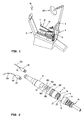
- a previously known dental treatment unit 10 comprises a chair 9 for the patient to be treated, a handpiece rest 8, which is movably attached to a pivoting arm 7, a supply unit 6 with connections to media sources such as electricity, water and pressurized gas, in particular compressed air, and a lighting device 6A , Furthermore, at least one supply line 19, which is connected to the supply unit 6 or to the connections to the media sources and which has a coupling element 15 for connecting a dental hand instrument, is provided on the dental treatment unit 10.
- the connectable dental hand instrument may comprise, for example, a hand-operated pneumatic handpiece or a hand-operated electric handpiece or handpiece for surgical, prosthetic or prophylactic applications.
- a plurality of supply lines 19, often four supply lines 19, each having a coupling element 15 for connecting different, in particular the previously mentioned, hand instruments are provided on a dental treatment unit 10.
- the hand instrument is a dental laser handle 1, which is designed to deliver laser radiation to a preparation site.
- the laser handle 1 comprises a hollow, elongated, tubular or cylindrical outer sleeve 11, inside which a laser light source 59 (see FIG. 5 ), in particular at least one laser diode.
- the outer sleeve 11 has at one of its two ends a connecting device 13 with a first coupling element 14 which is detachably connected to the second coupling element 15 of the supply line 19.
- a light emitting opening 4A, 4B for emitting the laser light radiation.
- the light emitting opening 4A is of a straight light guide 12A
- the light emitting opening 4B is penetrated by a bent light guide 12B, wherein the light guides 12A, 12B are part of the light emitting device of the laser handle 1 or alternatively connect to the provided inside the outer sleeve 11 light emitting device.
- a display device 17 and a plurality of adjusting or control elements 18A - 18E are further provided.
- a control device which preferably comprises a microcontroller, and which is connected to the display device 17 and the setting or control elements 18A-18E and to the laser light source 59.
- the user can exercise the following functions via the setting or control elements 18A-18E:
- the control element 18E which comprises a pushbutton or switch, the user can switch on or off the laser light source 59.
- the control device has a control circuit which, for example, upon actuation of the button, receives a control signal and interrupts or produces the power supply to the laser light source 59 electronically or by means of a switch in response to this control signal.
- the control element 18A serves to select different, preset operating programs for various dental applications, for example for periodontal, endodontic, surgical or prophylactic treatments. By actuating the control element 18A, the user calls up these programs and selects the desired one Program off.
- the operating programs differ in one or more operating parameters, for example in the power output by the laser light source 59, in the operating mode (pulsed or continuous laser light output), in the pulse width or pulse duration during pulsed operation or in the quantity of coolant to be dispensed onto the preparation site.
- the respective values for these or other parameters are displayed for each operating program on the display device 17, which has, for example, an LCD display.
- the programs are stored in a non-volatile memory unit of the control device, in particular in a non-rewritable memory (ROM memory).
- the control element 18D is used to change individual operating parameters of the laser light source 59, for example the power, the operating mode (pulsed or continuous laser light output), the pulse width or the pulse duration during pulsed operation.
- individual operating parameters of the laser light source 59 for example the power, the operating mode (pulsed or continuous laser light output), the pulse width or the pulse duration during pulsed operation.
- one or more operating parameters can be changed by the user.
- the changed values are stored in a memory unit in the form of a read-write memory, for example a RAM memory, the control device and serve in operation of the laser handle 1 in a known manner as a limit or default values.
- the selected values of the operating parameters particularly preferably also remain after the end of the treatment or after completion of the power supply automatically or alternatively after actuation of serving as a memory function key control element 18C stored in the non-volatile memory unit, so that the user again finds these parameters in the next treatment.
- the actuator 18B is used to turn on and off a lighting device, in particular a light emitting diode for emitting visible light, the laser handle 1 and / or for varying the illuminance.
- a lighting device in particular a light emitting diode for emitting visible light, the laser handle 1 and / or for varying the illuminance.
- the control device is connected to the lighting device and switches, depending on the control signals received from the control element 18B, the power supply to the lighting device electronically or by means of a switch or changes the illuminance, for example by means of pulse width modulation.
- Another, mechanical actuator 18F in the form of a collar serves to adjust the flow rate of a cooling fluid, in particular a spray liquid, through a channel in the first coupling element 14 and through one with the channel connected spray line in the laser handle 1 to the head piece 2A, 2B is passed.
- the adjusting ring 18F is connected to a control valve in the spray line for varying the flow rate of the cooling fluid.
- the detailed structure of the first coupling element 14 of the laser handle 1 is made FIG. 4 seen.
- the first coupling element 14 comprises six media connections 20-25 which are arranged on the first coupling element 14 in such a way that the first coupling element 14 is releasably connectable to the second coupling element 15 of the supply line 19, the second coupling element 15 initially for connection to a dental hand instrument without laser light source is provided.
- the dimensions of the six media ports 20-25 are also sized to be compatible with the media ports, for example, the media lines 16 of the second clutch element 15.
- a first media port 25 is arranged, which comprises an inlet opening and a bore and via the second coupling element 15 with a fluid source, preferably a compressed air source, is connectable.
- a fluid source preferably a compressed air source
- To the media port 25 includes in the interior of the laser handle 1, a line which directs the fluid to the head piece 2A, 2B, from where it is discharged to cool the preparation site via one or more openings.
- the fluid is mixed before delivery to the preparation site with a second fluid, for example water, in a mixing chamber of the laser handle 1.
- a second fluid for example water
- the second fluid enters the laser handle 1 via a further media connection 24, which likewise comprises an inlet opening and a bore and can be connected via the second coupling element 15 to a fluid source, preferably a water connection, and is conveyed in a separate line through the laser handle 1 led to the mixing chamber.
- a respective media connection 22, 23 is arranged, the electrical contacts, for example metallic bushings or pins. From these two media connections 22, 23, electrical lines extend to the electrical consumers in the laser handle 1, in particular to the laser light source, to the controller, to the setting or control elements 18A-18E and optionally to a heat sink for the laser light source 59.
- Both media connections 20, 21 each comprise an inlet opening and a bore.
- the medium connection 21 with the smaller diameter is in turn connectable via the second coupling element 15 to a fluid source, preferably a compressed air source, so that compressed air can be conveyed into the laser handle 1, which is used to cool the laser light source.
- the compressed air exits from the bore of the first coupling element 14 directly into the interior of the outer sleeve 11.
- the compressed air which has been heated after passing through or around the laser light source and / or a heat sink, is conducted in the outer sleeve 11 and returned to the supply line 19 through the medium connection 20.
- connection pattern of the first coupling element 14, ie the spatial arrangement of the media connections 20-25, is matched to the connection pattern of the second coupling element 15 of the supply line 19 so that the two coupling elements 14, 15 can be connected to one another, in particular can be plugged together.
- the connection diagram of the second coupling element 15 thus resembles the in FIG. 4 illustrated connection image, wherein the individual media connections, for example in the form of media lines 16 or electrical contacts, are arranged laterally reversed.
- the in FIG. 3 illustrated laser handle 3 is substantially similar to the handle 1, so that primarily the differences are described below.
- the laser handle 3 has a hollow cylindrical outer sleeve 31, at one end of which there is also a cylindrical connecting device 33 with a first coupling element 34.
- the laser handle 3 can be connected to a supply hose of a dental treatment unit via the first coupling element 34, so that the laser handle 3 can be operated with the media made available by the dental treatment unit.
- the media connections 40-44 are arranged differently on the first coupling element 34.
- the two pairs, arranged in the middle of the end face 37 media ports 40, 41 each comprise a short, projecting beyond the end face 37 pipe section and the first coupling element 34 passing through hole.
- the media port 41 with the smaller diameter is connected via the second coupling element of the supply line with a fluid source, preferably a compressed air source, connectable, so that compressed air is conveyed into the laser handle 3, which is used for cooling the laser light source.
- the compressed air exits from the bore of the first coupling element 34 directly into the interior of the outer sleeve 31.
- the compressed air which has been heated after passing through or around the laser light source and / or a heat sink, is conducted in the outer sleeve 31 and through the media connection 40 and returned to the supply line.
- the media ports 40, 41 On a first side 35 of the media ports 40, 41 are paired two other media ports 42, 43 are provided, which are designed as electrical contacts and two pins and the first coupling element 34 passes through lines.
- the lines are connected to one or more electrical consumers in the laser handle 3, in particular to the laser light source.
- the media connection 44 comprises an inlet opening and a bore and can be connected via the second coupling element of the supply line to a fluid source, preferably a water connection.
- a fluid source preferably a water connection.
- To the media port 44 includes in the interior of the laser handle 3, a line which directs the fluid to the vicinity of the laser light emitting opening, from where it is discharged to cool the preparation site via one or more openings.
- a further media connection is present instead of the closure element 45, then this is preferably connectable to a further fluid source, in particular compressed air, so that, as described above for the laser handle 1 and the two media connections 24, 25, an air-water Spray mixture produced and deliverable to the preparation site.
- a further fluid source in particular compressed air
- the closure element 45 comprises a cylindrical pin which is inserted into an opening or bore of the second coupling element arranged on the supply line can be used.
- sealing elements 45 are provided on the closure element, which additionally seal the opening of the second coupling element.
- connection diagram of the first coupling element 34 that is, the spatial arrangement of the media ports 40-44 and the closure member 45, matched to the connection diagram of the second coupling element of the supply line, so that the two coupling elements are connected to each other, in particular fauxsteckbar.
- the connection diagram of the second coupling element thus resembles that in FIG FIG. 3 illustrated connection image, wherein the individual media connections, for example in the form of media lines, holes, openings or electrical contacts, side or mirror-inverted.
- the in FIG. 5 It has an elongated, cylindrical outer sleeve 51 with an interior or cavity 52, in which the laser light source 59, for example, a laser diode and other device, for example the control device , the lighting device, media line for the spray liquid, etc. are included.
- the connecting device 53 At one end of the outer sleeve 51 is the connecting device 53 with the first coupling element 54 for releasably connecting the laser handle 5 to the supply line of the dental treatment unit, so that the laser handle 5 is again operable with the provided by the dental treatment unit available media.
- the first coupling element 54 of the laser handle 5 in turn comprises two media connections formed as electrical contacts for supplying the laser light source 59 (due to the selected cutting plane through the laser handle 5, these are not shown) and two paired media ports 60, 61.
- the media ports 60, 61 each comprise a short, over the end face 57 projecting pipe section and a first coupling element 54 passing through hole.
- the smaller diameter media port 61 is connectable to a fluid source, preferably a compressed air source, via the second coupling element of the supply line so that compressed air can be conveyed into the laser handle 5 used to cool the laser light source 59.
- the compressed air passes from the bore or from the pipe section of the first coupling element 54 in a arranged in the interior of the outer sleeve 51 and connected to the bore air line 56 via. Through one or more openings 58, the compressed air exits the air line 56 and is on the heat sink 55 is directed so that the compressed air flows around it, absorbs heat from the heat sink 55 and this convective dissipates from the heat sink 55 and from the laser handle 5. For this purpose, the heated compressed air in the outer sleeve 51 is passed back to the media port 60 and discharged through this into the supply line or to the environment.
- the heat sink 55 comprises a heat-conducting metal body, for example a metal sheet, and / or a heat sink, in the interior of which a vaporizable liquid is contained (a so-called heat pipe or heat pipe).
- the heat sink 55 is connected to the laser light source 59, preferably having an attachment or connection device 55A for the laser light source 59 at one end.
- the fastening or connecting device 55A is designed in particular as compared to the other heat sink widened platform.
- the laser light source 59 preferably the laser light source 59 and at least parts of the electrical or electronic components for transforming current parameters of the current provided by the dental treatment unit, for example capacitors, SMD resistors or a microcontroller, are particularly preferably additionally arranged at least parts of the control device of the laser handle 5.
- the laser light source 59 is preferably arranged in the laser handle 5, in particular on the fastening or connecting device 55A, such that at least a substantial part of the radiation emanatable from it can be emitted from the connection device 53 or in the direction of the light emission opening of the laser handle 5.
- at least one of the light emission surfaces of the laser light source 59 in the presence of a plurality of light emission surfaces preferably the largest area of light emission area, in the direction of the light emission opening.
- the laser light source 59 thus emits a substantial part of the radiation emanating from it along or parallel to the longitudinal axis 62 of the laser handle 5.
- the invention is not limited to the exemplary embodiments described, but encompasses all laser handles, laser treatment devices or dental treatment units which use or include the principal principle of operation of the invention.
Landscapes
- Health & Medical Sciences (AREA)
- Oral & Maxillofacial Surgery (AREA)
- Dentistry (AREA)
- Epidemiology (AREA)
- Life Sciences & Earth Sciences (AREA)
- Animal Behavior & Ethology (AREA)
- General Health & Medical Sciences (AREA)
- Public Health (AREA)
- Veterinary Medicine (AREA)
- Physics & Mathematics (AREA)
- Optics & Photonics (AREA)
- Dental Tools And Instruments Or Auxiliary Dental Instruments (AREA)
Priority Applications (1)
| Application Number | Priority Date | Filing Date | Title |
|---|---|---|---|
| EP08005555A EP2105108A1 (fr) | 2008-03-26 | 2008-03-26 | Pièce à main dentaire à laser et unité de traitement dentaire avec une telle pièce à main |
Applications Claiming Priority (1)
| Application Number | Priority Date | Filing Date | Title |
|---|---|---|---|
| EP08005555A EP2105108A1 (fr) | 2008-03-26 | 2008-03-26 | Pièce à main dentaire à laser et unité de traitement dentaire avec une telle pièce à main |
Publications (1)
| Publication Number | Publication Date |
|---|---|
| EP2105108A1 true EP2105108A1 (fr) | 2009-09-30 |
Family
ID=39691245
Family Applications (1)
| Application Number | Title | Priority Date | Filing Date |
|---|---|---|---|
| EP08005555A Withdrawn EP2105108A1 (fr) | 2008-03-26 | 2008-03-26 | Pièce à main dentaire à laser et unité de traitement dentaire avec une telle pièce à main |
Country Status (1)
| Country | Link |
|---|---|
| EP (1) | EP2105108A1 (fr) |
Citations (6)
| Publication number | Priority date | Publication date | Assignee | Title |
|---|---|---|---|---|
| DE2549177A1 (de) * | 1975-11-03 | 1977-05-05 | Siemens Ag | Kupplungsvorrichtung fuer zahnaerztliche handstuecke |
| US4826431A (en) * | 1986-06-12 | 1989-05-02 | Kabushiki Kaisha Morita Seisakusho | Medical laser handpiece |
| US4940411A (en) | 1988-08-25 | 1990-07-10 | American Dental Laser, Inc. | Dental laser method |
| EP0626229A1 (fr) * | 1993-05-21 | 1994-11-30 | LASER MEDICAL TECHNOLOGY, Inc. | Laser solide pour enlever des tissus physiologiques |
| EP0780097A2 (fr) | 1995-12-20 | 1997-06-25 | Dentalwerk Bürmoos Gesellschaft M.B.H. | Dispositifs et méthodes laser pour utilisation médicale, notamment dentaire |
| EP1726269A1 (fr) * | 2005-05-27 | 2006-11-29 | CASTELLINI S.p.A. | Unité dentaire |
-
2008
- 2008-03-26 EP EP08005555A patent/EP2105108A1/fr not_active Withdrawn
Patent Citations (6)
| Publication number | Priority date | Publication date | Assignee | Title |
|---|---|---|---|---|
| DE2549177A1 (de) * | 1975-11-03 | 1977-05-05 | Siemens Ag | Kupplungsvorrichtung fuer zahnaerztliche handstuecke |
| US4826431A (en) * | 1986-06-12 | 1989-05-02 | Kabushiki Kaisha Morita Seisakusho | Medical laser handpiece |
| US4940411A (en) | 1988-08-25 | 1990-07-10 | American Dental Laser, Inc. | Dental laser method |
| EP0626229A1 (fr) * | 1993-05-21 | 1994-11-30 | LASER MEDICAL TECHNOLOGY, Inc. | Laser solide pour enlever des tissus physiologiques |
| EP0780097A2 (fr) | 1995-12-20 | 1997-06-25 | Dentalwerk Bürmoos Gesellschaft M.B.H. | Dispositifs et méthodes laser pour utilisation médicale, notamment dentaire |
| EP1726269A1 (fr) * | 2005-05-27 | 2006-11-29 | CASTELLINI S.p.A. | Unité dentaire |
Similar Documents
| Publication | Publication Date | Title |
|---|---|---|
| DE3719561C2 (de) | Medizinisches Lichtbestrahlungshandstück | |
| DE3526877C2 (fr) | ||
| EP2548530B1 (fr) | Dispositif d'éclairage pour instrument médical, notamment dentaire | |
| DE69401949T2 (de) | Chirurgisches gerät, insbesondere für die zahnchirurgie | |
| DE3500085A1 (de) | Zahnaerztliches handstueck | |
| EP1946714B1 (fr) | Instrument chirurgical destiné au traitement de tissus tumoraux | |
| EP1740106B1 (fr) | Applicateur pour la chirurgie a jets d'eau | |
| EP1391175A2 (fr) | Pièce à main médicale ou dentaire en forme de barre comportant un écran | |
| EP2335638A1 (fr) | Dispositif de traitement médical en particulier dentaire pour délivrer une substance | |
| EP1391182A2 (fr) | Piece à main avec un élément luminescent à son extrémité avant | |
| EP1475052B1 (fr) | Appareil de photopolymérisation avec un ventilateur | |
| DE3716410A1 (de) | Anschlussvorrichtung fuer ein handstueck mit beleuchtung | |
| EP2105108A1 (fr) | Pièce à main dentaire à laser et unité de traitement dentaire avec une telle pièce à main | |
| WO2016102524A1 (fr) | Pièce à main ou coudée médicale, en particulier dentaire | |
| DE102010033240B4 (de) | Handstückeinheit für eine Einweg-Spüldüseneinheit zur Reinigung und/oder Spülung von Operationswunden | |
| EP0199808B1 (fr) | Dispositif de soins buccaux | |
| EP2012934B1 (fr) | Pomme de douche multifonctionnelle | |
| AT405365B (de) | Handstück für ein lasergerät und kupplungsstück für ein handstück eines lasergerätes | |
| EP0230010B1 (fr) | Appareil de dentisterie | |
| DE3534342C1 (en) | Light transmitting dental hand-tool - for curing polymer based fillings | |
| DE2701229A1 (de) | Zahnaerztliches handstueck | |
| DE202007013012U1 (de) | Chirurgisches Instrument | |
| EP2301472B1 (fr) | Pièce à main dentaire | |
| EP2124812A1 (fr) | Pièce à main médicale, en particulier médico-dentaire, comportant deux ouvertures de sortie distinctes pour des substances | |
| DE3706943A1 (de) | Beleuchtungseinrichtung fuer ein zahnaerztliches handinstrument |
Legal Events
| Date | Code | Title | Description |
|---|---|---|---|
| PUAI | Public reference made under article 153(3) epc to a published international application that has entered the european phase |
Free format text: ORIGINAL CODE: 0009012 |
|
| AK | Designated contracting states |
Kind code of ref document: A1 Designated state(s): AT BE BG CH CY CZ DE DK EE ES FI FR GB GR HR HU IE IS IT LI LT LU LV MC MT NL NO PL PT RO SE SI SK TR |
|
| AX | Request for extension of the european patent |
Extension state: AL BA MK RS |
|
| AKX | Designation fees paid | ||
| REG | Reference to a national code |
Ref country code: DE Ref legal event code: 8566 |
|
| STAA | Information on the status of an ep patent application or granted ep patent |
Free format text: STATUS: THE APPLICATION IS DEEMED TO BE WITHDRAWN |
|
| 18D | Application deemed to be withdrawn |
Effective date: 20100331 |