EP2105190A1 - Procédé et dispositif de séparation de dioxyde de carbone d'un gaz d'échappement d'une centrale à combustible fossile - Google Patents
Procédé et dispositif de séparation de dioxyde de carbone d'un gaz d'échappement d'une centrale à combustible fossile Download PDFInfo
- Publication number
- EP2105190A1 EP2105190A1 EP08005849A EP08005849A EP2105190A1 EP 2105190 A1 EP2105190 A1 EP 2105190A1 EP 08005849 A EP08005849 A EP 08005849A EP 08005849 A EP08005849 A EP 08005849A EP 2105190 A1 EP2105190 A1 EP 2105190A1
- Authority
- EP
- European Patent Office
- Prior art keywords
- absorption
- carbon dioxide
- absorption medium
- exhaust gas
- desorption
- Prior art date
- Legal status (The legal status is an assumption and is not a legal conclusion. Google has not performed a legal analysis and makes no representation as to the accuracy of the status listed.)
- Withdrawn
Links
- CURLTUGMZLYLDI-UHFFFAOYSA-N Carbon dioxide Chemical compound O=C=O CURLTUGMZLYLDI-UHFFFAOYSA-N 0.000 title claims abstract description 368
- 229910002092 carbon dioxide Inorganic materials 0.000 title claims abstract description 184
- 239000001569 carbon dioxide Substances 0.000 title claims abstract description 184
- 238000000034 method Methods 0.000 title claims abstract description 144
- 238000010521 absorption reaction Methods 0.000 claims abstract description 299
- 238000003795 desorption Methods 0.000 claims abstract description 97
- 238000004140 cleaning Methods 0.000 claims abstract description 55
- 239000002904 solvent Substances 0.000 claims abstract description 26
- 238000002485 combustion reaction Methods 0.000 claims abstract description 18
- 238000012546 transfer Methods 0.000 claims abstract description 12
- 239000012530 fluid Substances 0.000 claims abstract description 10
- 239000007788 liquid Substances 0.000 claims abstract description 9
- 239000002803 fossil fuel Substances 0.000 claims abstract description 7
- 150000001412 amines Chemical class 0.000 claims abstract description 5
- 239000000443 aerosol Substances 0.000 claims abstract description 4
- 239000000725 suspension Substances 0.000 claims abstract description 4
- 238000000926 separation method Methods 0.000 claims description 38
- 239000003599 detergent Substances 0.000 claims description 6
- 239000012716 precipitator Substances 0.000 claims description 6
- 238000010438 heat treatment Methods 0.000 claims description 5
- 238000011084 recovery Methods 0.000 claims description 4
- 238000013461 design Methods 0.000 claims description 3
- 239000007789 gas Substances 0.000 abstract description 86
- XLYOFNOQVPJJNP-UHFFFAOYSA-N water Substances O XLYOFNOQVPJJNP-UHFFFAOYSA-N 0.000 abstract description 2
- 238000000746 purification Methods 0.000 description 14
- 239000006096 absorbing agent Substances 0.000 description 7
- 230000008929 regeneration Effects 0.000 description 6
- 238000011069 regeneration method Methods 0.000 description 6
- 238000011161 development Methods 0.000 description 5
- 230000018109 developmental process Effects 0.000 description 5
- HZAXFHJVJLSVMW-UHFFFAOYSA-N 2-Aminoethan-1-ol Chemical compound NCCO HZAXFHJVJLSVMW-UHFFFAOYSA-N 0.000 description 4
- 238000007906 compression Methods 0.000 description 4
- 238000001816 cooling Methods 0.000 description 4
- CRVGTESFCCXCTH-UHFFFAOYSA-N methyl diethanolamine Chemical compound OCCN(C)CCO CRVGTESFCCXCTH-UHFFFAOYSA-N 0.000 description 4
- 239000007787 solid Substances 0.000 description 4
- MWUXSHHQAYIFBG-UHFFFAOYSA-N Nitric oxide Chemical compound O=[N] MWUXSHHQAYIFBG-UHFFFAOYSA-N 0.000 description 3
- 150000001875 compounds Chemical class 0.000 description 3
- 208000028659 discharge Diseases 0.000 description 3
- 239000000203 mixture Substances 0.000 description 3
- IJGRMHOSHXDMSA-UHFFFAOYSA-N Atomic nitrogen Chemical compound N#N IJGRMHOSHXDMSA-UHFFFAOYSA-N 0.000 description 2
- UGFAIRIUMAVXCW-UHFFFAOYSA-N Carbon monoxide Chemical compound [O+]#[C-] UGFAIRIUMAVXCW-UHFFFAOYSA-N 0.000 description 2
- ATUOYWHBWRKTHZ-UHFFFAOYSA-N Propane Chemical compound CCC ATUOYWHBWRKTHZ-UHFFFAOYSA-N 0.000 description 2
- RAHZWNYVWXNFOC-UHFFFAOYSA-N Sulphur dioxide Chemical compound O=S=O RAHZWNYVWXNFOC-UHFFFAOYSA-N 0.000 description 2
- 230000006978 adaptation Effects 0.000 description 2
- 230000006835 compression Effects 0.000 description 2
- 238000005265 energy consumption Methods 0.000 description 2
- 238000005516 engineering process Methods 0.000 description 2
- 230000002349 favourable effect Effects 0.000 description 2
- 239000003546 flue gas Substances 0.000 description 2
- 238000009434 installation Methods 0.000 description 2
- VNWKTOKETHGBQD-UHFFFAOYSA-N methane Chemical compound C VNWKTOKETHGBQD-UHFFFAOYSA-N 0.000 description 2
- 239000012046 mixed solvent Substances 0.000 description 2
- 238000004064 recycling Methods 0.000 description 2
- 239000000126 substance Substances 0.000 description 2
- 239000002918 waste heat Substances 0.000 description 2
- OKTJSMMVPCPJKN-UHFFFAOYSA-N Carbon Chemical compound [C] OKTJSMMVPCPJKN-UHFFFAOYSA-N 0.000 description 1
- OTMSDBZUPAUEDD-UHFFFAOYSA-N Ethane Chemical compound CC OTMSDBZUPAUEDD-UHFFFAOYSA-N 0.000 description 1
- VGGSQFUCUMXWEO-UHFFFAOYSA-N Ethene Chemical compound C=C VGGSQFUCUMXWEO-UHFFFAOYSA-N 0.000 description 1
- FFBHFFJDDLITSX-UHFFFAOYSA-N benzyl N-[2-hydroxy-4-(3-oxomorpholin-4-yl)phenyl]carbamate Chemical compound OC1=C(NC(=O)OCC2=CC=CC=C2)C=CC(=C1)N1CCOCC1=O FFBHFFJDDLITSX-UHFFFAOYSA-N 0.000 description 1
- 239000001273 butane Substances 0.000 description 1
- 229910052799 carbon Inorganic materials 0.000 description 1
- 239000003245 coal Substances 0.000 description 1
- 230000006866 deterioration Effects 0.000 description 1
- 230000002542 deteriorative effect Effects 0.000 description 1
- 238000007599 discharging Methods 0.000 description 1
- 230000000694 effects Effects 0.000 description 1
- 238000004519 manufacturing process Methods 0.000 description 1
- IJDNQMDRQITEOD-UHFFFAOYSA-N n-butane Chemical compound CCCC IJDNQMDRQITEOD-UHFFFAOYSA-N 0.000 description 1
- OFBQJSOFQDEBGM-UHFFFAOYSA-N n-pentane Natural products CCCCC OFBQJSOFQDEBGM-UHFFFAOYSA-N 0.000 description 1
- 229910052757 nitrogen Inorganic materials 0.000 description 1
- 239000002245 particle Substances 0.000 description 1
- 239000003208 petroleum Substances 0.000 description 1
- 238000010248 power generation Methods 0.000 description 1
- 238000001556 precipitation Methods 0.000 description 1
- 238000012545 processing Methods 0.000 description 1
- 239000001294 propane Substances 0.000 description 1
- 230000005855 radiation Effects 0.000 description 1
- 230000001172 regenerating effect Effects 0.000 description 1
- 238000012958 reprocessing Methods 0.000 description 1
- 239000004071 soot Substances 0.000 description 1
- 238000003860 storage Methods 0.000 description 1
- 239000002912 waste gas Substances 0.000 description 1
Images

Classifications
-
- B—PERFORMING OPERATIONS; TRANSPORTING
- B01—PHYSICAL OR CHEMICAL PROCESSES OR APPARATUS IN GENERAL
- B01D—SEPARATION
- B01D53/00—Separation of gases or vapours; Recovering vapours of volatile solvents from gases; Chemical or biological purification of waste gases, e.g. engine exhaust gases, smoke, fumes, flue gases, aerosols
- B01D53/14—Separation of gases or vapours; Recovering vapours of volatile solvents from gases; Chemical or biological purification of waste gases, e.g. engine exhaust gases, smoke, fumes, flue gases, aerosols by absorption
- B01D53/1456—Removing acid components
- B01D53/1475—Removing carbon dioxide
-
- B—PERFORMING OPERATIONS; TRANSPORTING
- B01—PHYSICAL OR CHEMICAL PROCESSES OR APPARATUS IN GENERAL
- B01D—SEPARATION
- B01D53/00—Separation of gases or vapours; Recovering vapours of volatile solvents from gases; Chemical or biological purification of waste gases, e.g. engine exhaust gases, smoke, fumes, flue gases, aerosols
- B01D53/14—Separation of gases or vapours; Recovering vapours of volatile solvents from gases; Chemical or biological purification of waste gases, e.g. engine exhaust gases, smoke, fumes, flue gases, aerosols by absorption
- B01D53/1425—Regeneration of liquid absorbents
-
- Y—GENERAL TAGGING OF NEW TECHNOLOGICAL DEVELOPMENTS; GENERAL TAGGING OF CROSS-SECTIONAL TECHNOLOGIES SPANNING OVER SEVERAL SECTIONS OF THE IPC; TECHNICAL SUBJECTS COVERED BY FORMER USPC CROSS-REFERENCE ART COLLECTIONS [XRACs] AND DIGESTS
- Y02—TECHNOLOGIES OR APPLICATIONS FOR MITIGATION OR ADAPTATION AGAINST CLIMATE CHANGE
- Y02C—CAPTURE, STORAGE, SEQUESTRATION OR DISPOSAL OF GREENHOUSE GASES [GHG]
- Y02C20/00—Capture or disposal of greenhouse gases
- Y02C20/40—Capture or disposal of greenhouse gases of CO2
Definitions
- the invention relates to a method for operating a fossil-fired power plant and in particular a method for separating carbon dioxide from an exhaust gas of a fossil-fired power plant.
- the invention also relates to a fossil-fired power plant with a separation device for separating carbon dioxide from an exhaust gas.
- the combustion of a fossil fuel a carbon dioxide-containing exhaust gas.
- the exhaust gas contains other combustion products such as e.g. the gases nitrogen, sulfur dioxide, nitrogen oxide and water vapor as well as solid particles dusts and soot.
- the exhaust gas is released after extensive separation of the solid components into the atmosphere.
- the carbon dioxide accumulating in the atmosphere impedes the heat radiation of our earth and favors by the so-called greenhouse effect an increase of the earth's surface temperature.
- carbon dioxide can be separated from the exhaust gas.
- the described separation of carbon dioxide is carried out by the absorption-desorption process with a detergent.
- the exhaust gas is in an absorption column contacted with a selective solvent as a detergent.
- the absorption of carbon dioxide takes place by a chemical or physical process.
- the purified waste gas is discharged from the absorption column for further processing or discharge.
- the loaded with carbon dioxide solvent is passed to separate the carbon dioxide and regeneration of the solvent in a desorption column.
- the separation in the desorption column can be carried out thermally. In this case, a gas-vapor mixture of gaseous carbon dioxide and evaporated solvent is expelled from the loaded solvent. The evaporated solvent is then separated from the gaseous carbon dioxide.
- the carbon dioxide can now be compressed, cooled and liquefied in several stages. In liquid or frozen state, the carbon dioxide can then be sent for storage or recycling. The regenerated solvent is returned to the absorber column, where it can again absorb carbon dioxide from the carbon dioxide-containing offgas.
- the proposed recycling plant for recovering a gaseous component from a process gas comprises an absorber using a thin solvent and a semi-thin solvent which absorbs the gaseous component from the process gas, thereby producing an enriched solvent, a semi-enriched solvent and a thin process gas ,
- a regenerator is coupled to the absorber, wherein the regenerator enriches the gaseous component Solvent, whereby the thin solvent and the semi-thin solvent are recovered.
- a solvent flow control element is coupled to the absorber and combines at least a portion of the semi-enriched solvent with at least a portion of the semi-thin solvent to form a mixed solvent.
- a cooler is coupled to the absorber, which cools the mixed solvent.
- the cooled solvent is then passed through a connecting element in the absorber.
- the economy of a fossil-fired power plant with carbon dioxide separation device, which is connected in or after the fossil-fired power plant is therefore significantly lower than without.
- An object of the invention is to propose a method for separating carbon dioxide from an exhaust gas of a fossil-fired power plant, which allows a high separation efficiency at the same time favorable overall system efficiency of the power plant process.
- Another object of the invention is to propose a fossil-fired power plant with integrated carbon dioxide separation device, which enables a high separation efficiency with a simultaneously favorable overall efficiency of the power plant.
- the object directed to a method is achieved according to the invention with a method for separating carbon dioxide from an exhaust gas of a fossil-fired power plant, in which a fossil fuel is burned in a combustion process, wherein a carbon dioxide-containing exhaust gas is generated, wherein in a pre-cleaning step with at least a first Absorption process, the carbon dioxide-containing exhaust gas is brought into contact with a first absorption medium, wherein carbon dioxide is absorbed by the absorption medium, wherein a first loaded absorption medium and a prepurified exhaust gas is formed, which is partially released from carbon dioxide, and wherein in a final cleaning step with a second absorption process the pre-cleaned in the prepurifying step exhaust gas is brought into contact with a second absorption medium, wherein carbon dioxide is absorbed by the absorption medium, wherein a second loaded absorption medium and a purified Abg As is formed, which is largely exempt from carbon dioxide.
- the invention is based on the consideration that in a combustion process by the combustion of a fossil fuel, a carbon dioxide-containing exhaust gas is generated, which is freed of carbon dioxide in at least two purification steps in an absorption process downstream of the combustion process.
- fossil fuel are gases such. Erdas (methane, ethane, propane, butane, ethene), solids such as e.g. Brown or hard coal and liquids such as e.g. Petroleum conceivable.
- the pre-cleaning step with at least one first absorption process, a pre-cleaning of the carbon dioxide-containing exhaust gas takes place first.
- the carbon dioxide-containing exhaust gas is brought into contact with at least the first absorption medium, wherein carbon dioxide is absorbed by the absorption medium.
- a first laden absorption medium and a pre-purified exhaust gas are formed.
- the pre-cleaned exhaust gas is initially partially released from carbon dioxide.
- the final cleaning step with a second absorption process, the final cleaning of the at least the first cleaning step pre-cleaned carbon dioxide-containing exhaust gas takes place.
- the prepurified carbon dioxide-containing exhaust gas is brought in the second absorption process in contact with the second absorption medium, wherein carbon dioxide is absorbed by the absorption medium.
- the second absorption process leaving a loaded absorption medium and a largely exempt from carbon dioxide exhaust.
- the loaded absorption medium from the first and the second purification step and the exhaust gas largely freed of carbon dioxide can now be supplied for further use.
- the invention initially provides a pre-cleaning step with at least one first absorption process. Depending on the configuration of the process, however, the presence of a second first or several first absorption processes may also be advantageous.
- the carbon dioxide-containing exhaust gas is first subjected to a pre-cleaning step and then to a final cleaning step.
- a significantly more efficient operation of a carbon dioxide precipitation device, in particular in a power plant is possible, which is reduced compared to a conventional mode of operation in energy demand.
- the energy to operate the carbon dioxide capture device of a fossil-fired power plant is typically provided by steam, e.g. is taken from the boiler of a steam power plant or the heat recovery steam generator of a gas and steam turbine power plant. Since a saving of this steam is achieved by the significantly more efficient operation of the carbon dioxide precipitator, the efficiency of the power plant increases.
- the invention for separating carbon dioxide from an exhaust gas of a fossil-fired power plant by a multi-stage absorption thus allows compared to the prior art, a substantially cheaper operation of a carbon dioxide precipitator.
- the invention also allows the subsequent installation of a carbon dioxide precipitator while meeting economic conditions.
- gaseous carbon dioxide is released from the loaded absorption medium in a desorption process.
- a regenerated absorption medium is formed.
- gaseous carbon dioxide is expelled thermally from the loaded absorption medium.
- this heat is provided by steam, which is taken for example from the boiler of a steam power plant or the heat recovery steam generator of a gas and steam turbine power plant.
- carbon dioxide is released from the first loaded absorption medium in the pre-purification step following the first absorption process with at least one first desorption process, wherein the absorption medium is guided in a first cycle between the first absorption process and the first desorption process.
- gaseous carbon dioxide is released from the second loaded absorption medium with a second desorption process, wherein the absorption medium is guided in a second cycle between the second absorption process and the second desorption process.
- the carbon dioxide separation process By dividing the carbon dioxide separation process into a pre-cleaning and an end-cleaning step, it is possible to adapt the respective desorption process to the carbon dioxide content in the absorption medium. Depending on the configuration of the process, however, the presence of a second first or several first desorption processes may also be advantageous. This allows optimized operation of a carbon dioxide precipitator, which is reduced compared to a conventional mode of operation in energy demand.
- the respective desorption processes from pre-cleaning and final cleaning are separated from each other in terms of process technology.
- the respective desorption processes are arranged in at least two separate housings. An arrangement of the respective desorption processes in a housing is possible. Through the first and second circulation reuse of the absorption medium is possible.
- the pre- and final cleaning in at least two steps allows a different operation of the separate processes.
- an absorption medium which was only partially freed from carbon dioxide in at least the first desorption process is sufficient. This will be first achieved a rough cleaning. By the unnecessary complete cleaning, or regeneration of the absorption medium energy in the form of heat is saved.
- an absorption medium is required which, for example, has been largely completely freed from carbon dioxide in the second desorption process in order to be able largely to liberate the exhaust gas from the residual carbon dioxide. Since this absorption medium only a fine cleaning is necessary, this must also absorb even lower amounts of carbon dioxide. Due to the small amounts of carbon dioxide that must be expelled from the absorption medium, energy in the form of heat is also saved.
- an absorption medium which is different from the absorption medium in the second circulation can also be used in at least the first circulation.
- the respective absorption medium may e.g. be optimized in terms of the carbon dioxide content in the exhaust gas or the operating temperature.
- a fluid is advantageously proposed in the carbon dioxide separation method.
- a fluid in the method according to the invention offers considerable advantages in the passage of the medium into the process.
- Liquids, gases, aerosols or suspensions are suitable as fluid.
- the use of a vaporizable solvent is preferably proposed.
- a particularly good process run is achieved by a solution of H 2 O and amine derivatives as solvent.
- solutions under the names MEA (monoethanolamine) and MDEA (methyldiethanolamine) are known.
- heat is removed from regenerated absorption medium from at least the first circuit in a heat transfer process, and released to the loaded absorption medium from at least the first or the second circuit.
- a further embodiment provides a comparable heat transfer process in which heat is removed from regenerated absorption medium from the second circuit, and is discharged to the loaded absorption medium from at least the first cycle.
- the carbon dioxide separated off by the desorption process is compressed in a subsequent compressor process.
- the compression serves to simplify the further handling of the carbon dioxide.
- the heat of compression can also be used to support the desorption process. Furthermore, it is advantageous to store the compressed carbon dioxide.
- the carbon dioxide separation process is used in a fossil-fired steam power plant.
- the carbon dioxide separation process is used in a combined cycle power plant.
- the object directed to a fossil-fueled power plant is achieved according to the invention with a combustion device downstream of a carbon dioxide-containing Exhaust gas-permeable separator for carbon dioxide, comprising an absorption device for receiving carbon dioxide from the exhaust gas, characterized in that the absorption device comprises a first absorption unit for pre-cleaning the carbon dioxide-containing exhaust gas, and a second absorption unit for final purification of the carbon dioxide-containing exhaust gas, wherein the second absorption unit in the flow direction of Exhaust gas is connected downstream of the first absorption unit.
- the invention which is directed to a fossil-fueled power plant, is based on the consideration that the absorption device is part of the separation device connected downstream of the combustion device, has a first absorption unit for pre-cleaning and a second absorption unit for final purification of the carbon dioxide-containing exhaust gas.
- the first absorption unit the carbon dioxide-containing exhaust gas is brought into contact with an absorption medium, whereby carbon dioxide is taken up by the absorption medium.
- a first laden absorption medium and a pre-purified exhaust gas are formed.
- the pre-cleaned exhaust gas is initially partially released from carbon dioxide.
- the prepurified exhaust gas is brought into contact with a second absorption medium, wherein carbon dioxide is taken up by the absorption medium.
- a second laden absorption medium and a final purified exhaust gas are formed.
- the final cleaned exhaust gas is largely freed from carbon dioxide.
- the loaded absorption medium from the first and the second absorption unit as well as the largely freed of carbon dioxide exhaust gas can now be supplied for further use.
- the invention provides for a pre-cleaning with at least one first absorption unit.
- a pre-cleaning with at least one first absorption unit.
- an adaptation of the respective absorption unit to the carbon dioxide content in the exhaust gas can be achieved.
- a much more efficient operation of a carbon dioxide separation device is possible, which is reduced compared to a conventional gas purification device in the energy requirement.
- the respective absorption units for pre- and final cleaning are spatially separated from each other, and only connected by an exhaust pipe. The arrangement of the absorption units in a housing is possible.
- the invention for separating carbon dioxide from an exhaust gas of a fossil-fired power plant with a plurality of absorption units connected in series thus enables a substantially cheaper operation of a carbon dioxide separation device compared to the prior art.
- the invention also allows the subsequent installation of a carbon dioxide separation device while meeting economic conditions.
- the absorption device is designed as a column or column for the passage of an absorption medium.
- Absorption columns are available for a wide variety of industrial applications.
- a columnar Arrangement of the absorption device is space-saving and process-supporting.
- the carbon dioxide-containing exhaust gas is the counter-current to the absorption medium for the absorption of carbon dioxide.
- the absorption medium is introduced, for example, in the upper region of the absorption unit and discharged again in the lower region.
- the carbon dioxide-containing exhaust gas is in turn introduced into the lower region of the absorption unit and discharged in the upper region.
- the absorption medium comes in the upper region, where it is still relatively free of carbon dioxide, with the exhaust gas in contact, which has already released carbon dioxide in the lower region and is now charged only less with carbon dioxide.
- the absorption medium can thereby extract further carbon dioxide from the exhaust gas containing carbon dioxide.
- the absorption medium is conducted into the lower part of the absorption unit, where it is already partially loaded with carbon dioxide, it comes into contact with exhaust gas, which is still loaded with high amounts of carbon dioxide.
- the absorption medium, which is already partially laden with carbon dioxide, can already extract part of the carbon dioxide from the exhaust gas containing carbon dioxide here.
- the absorption device is followed by a desorption device for emitting carbon dioxide, which is connected via a respective line to and from the absorption device, and thus forms a circuit for the absorption medium.
- a desorption device for emitting carbon dioxide In the desorption device gaseous carbon dioxide is released from the loaded absorption medium. In this case, a regenerated absorption medium is formed.
- the desorption device As already proposed for the absorption device, it is also advantageous to design the desorption device as a column or column for the passage of the absorption medium.
- the desorption device downstream of the absorption device has at least one first desorption unit, which is connected to and connected to at least the first absorption unit via a respective line, so that at least one first circuit is formed for the absorption medium.
- the desorption device connected downstream of the absorption device has a second desorption unit, which is connected to the second absorption unit via a respective line in a supply and discharge, so that a second circuit is formed for the absorption medium.
- the absorption and desorption By dividing the absorption and desorption into at least a first and a second unit, it is possible to adapt the respective absorption or desorption on the carbon dioxide content in the absorption medium. Depending on the design of the separation device, however, the presence of a second first or several first desorption units may also be advantageous. This allows a much more efficient operation of a carbon dioxide separation device, which is reduced in energy consumption compared to a conventional gas purification device.
- the respective desorption for pre- and final cleaning are spatially separated from each other in their arrangement.
- the respective desorption units are arranged in at least two separate housings. An arrangement of the respective desorption in a housing is possible. Through the first and second circulation reuse of the absorption medium is possible.
- the pre- and final cleaning in at least two separate units allows a different operation. So is sufficient for the pre-cleaning in at least the first absorption unit, an absorption medium which has only been partially freed of carbon dioxide in at least the first desorption unit. As a result, a rough cleaning is achieved first. By the unnecessary complete cleaning, or regeneration of the absorption medium energy in the form of heat is saved.
- an absorption medium is needed, which was largely completely freed from carbon dioxide in the second desorption unit in order to be able to substantially free the exhaust gas from the residual carbon dioxide.
- This absorption medium only needs to absorb smaller amounts of carbon dioxide. The small amounts of carbon dioxide that must be expelled from the absorption medium, energy is saved, which is provided here in the form of heat.
- a heat exchanger which is primarily zu implementedd connected to at least the first desorption and primarily dissipative with at least the first absorption unit, and the secondary zu facedd with at least the first absorption unit and secondary discharge is connected to at least the first desorption ,
- the heat exchanger is thus connected in the first circuit.
- a heat exchanger is also connected in the second circuit, which is primarily zu facedd connected to the second desorption and primarily dissipative with the second absorption unit, and secondarily zu facedd connected to the second absorption unit and secondarily dissipative with the second desorption unit.
- the primary feed compound with the respective desorption unit removes heat from the regenerated absorption medium carried in the compound and delivers it to the laden absorption medium guided in the secondary dissipative compound.
- the proposed heat exchanger on the one hand, a preheating of the loaded absorption medium to the working temperature of the downstream desorption and on the other hand, a cooling of the regenerated absorption medium achieved to the working temperature of the downstream absorption unit. This saves heating energy for the absorption medium in the desorption unit and energy for cooling the absorption medium in the absorption unit.
- the desorption device comprises a heating device for the absorption medium, so that carbon dioxide can be expelled thermally from the absorption medium.
- the heater can use the falling in the overall process of the power plant heat.
- a heat exchanger is connected to the primary side with a steam line and the secondary side with the desorption to transfer heat into the heater.
- the desorption can be operated without additional waste heat from the overall process of the power plant. This is important, for example, when starting or stopping the separation device. As a result, the arrival or departure is supported, with a particularly efficient use of heat is provided.
- the first circuit is designed for the flow through a first absorption medium
- the second circuit is designed for the flow through a second absorption medium.
- a plurality of first absorption media are accordingly provided. This makes it possible to adapt the respective absorption medium to the respective absorption or desorption unit.
- the respective absorption medium may e.g. be optimized in terms of the carbon dioxide content in the exhaust gas or the operating temperature.
- the fossil-fired power plant is expediently designed in such a way that the separating device can be operated with an absorption medium suitable for the absorption of carbon dioxide, in particular a detergent for carbon dioxide is.
- a detergent while a fluid is preferred.
- a fluid offers considerable advantages in the passage.
- Liquids, gases, aerosols or suspensions are suitable as fluid.
- the use of a vaporizable solvent is preferably proposed.
- Particularly advantageous is the use of a solution of H 2 O and amine derivatives as detergent.
- solutions under the names MEA (monoethanolamine) and MDEA (methyldiethanolamine) are known.
- the fossil-fired power plant is designed as a steam power plant comprising a fired boiler and a steam turbine.
- the fossil-fueled power plant is configured as a gas and steam turbine plant comprising a gas turbine and a waste heat steam generator connected downstream of the gas turbine on the exhaust gas side, which is connected in the water-steam circuit of a steam turbine.
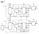
- the illustrated carbon dioxide separation method includes a combustion process 1, a pre-purification step 3, and a final purification step 3 '.
- the carbon dioxide-containing exhaust gas 2 formed in the combustion process is first supplied to a pre-purification step 3 and fed to a first absorption process 4.
- first absorption process 4 carbon dioxide from the carbon dioxide-containing exhaust gas 2 is taken up by a first regenerated absorption medium 9.
- the absorption process 4 leave a first laden absorption medium 5, as well as a pre-cleaned exhaust gas. 6
- the first loaded absorption medium 5 11 heat is removed in a first heat transfer process. Subsequently, it is guided into a desorption process 8, where it is introduced into a first desorption process 10.
- carbon dioxide is released from the first loaded absorption medium 5.
- the first regenerated absorption medium 9 and a first separated carbon dioxide 12 are discharged.
- the first separated carbon dioxide 12 is compressed in a first compression process 13 and discharged as a first compressed carbon dioxide 14.
- the first regenerated absorption medium 9 is heated in a first heat transfer process 11 and returned to the first absorption process 4.
- the absorption medium 9 is circulated, the first loaded absorption medium 5 being regenerated and returned to the absorption process as the first regenerated absorption medium 9.
- a final purification step 3 ' analogously to the pre-purification step 3, the pre-cleaned exhaust gas 6 is conducted into an absorption process 4'.
- the absorption process 4 ' carbon dioxide from the pre-purified exhaust gas 6 is taken up by a second regenerated absorption medium 9'.
- the Absorption process 4 ' leave a second loaded absorption medium 5' and a liberated from carbon dioxide exhaust gas. 7
- Heat is removed from the second loaded absorption medium 5 'in a second heat transfer process 11'. Subsequently, the second loaded absorption medium 5 'is led into the desorption process 8, where it is introduced into a second desorption process 10'. In the second desorption process 10 ', carbon dioxide is released from the second loaded absorption medium 5'. From the second desorption process 10 ', the second regenerated absorption medium 9' and a second separated carbon dioxide 12 'are discharged. The second separated carbon dioxide 12 'is compressed in a second compression process 13' and discharged as a second compressed carbon dioxide 14 '. The second regenerated absorption medium 9 'is heated in the second heat transfer process 11' and returned to the second absorption process 4 '. Thus, in the final cleaning step 3 ', the absorption medium 9' is circulated, the second loaded absorption medium 5 'being regenerated and returned to the absorption process as the second regenerated absorption medium 9'.
- the separation device 15 comprises an absorption device 16 and a desorption device 18th
- the combustion device 29 is connected to a fired boiler 25 for conducting a carbon dioxide-containing exhaust gas 2.
- the fired boiler 25 is also connected to direct steam to a steam turbine 26, which in turn drives a generator 27 for power generation.
- the fired boiler 25 for conducting the carbon dioxide-containing exhaust gas 2 is connected to a first absorption unit 17, which is part of the absorption device 16.
- the first absorption unit 17 is feeding with a first Line for regenerated absorption medium 20 connected to a first heat exchanger 22, with a first line for laden absorption medium 19 laxatively connected to the first heat exchanger 22, and for conducting a prepurified exhaust gas 6 with a second absorption unit 17 '.
- the first heat exchanger 22 is connected to a first desorption unit 21 of the desorption device 18 for conducting the loaded absorption medium 19 zu organizedd.
- the first desorption unit 21 is connected to a compressor 28 for conducting separated carbon dioxide 30.
- the first desorption unit 21 is connected to the first heat exchanger 22.
- the first heat exchanger 22 is connected to the absorption unit 17 of the absorption device 16 for conducting the regenerated absorption medium 20.
- the heat exchanger 23 is connected via a steam line 24 to the fired boiler 25 and the steam turbine 26.
- the second absorption unit 17 ' is connected to the second heat exchanger 22' for conducting a regenerated absorption medium 20 ', connected to the second heat exchanger 22' for conducting a loaded absorption medium 19 'and has a conduit for discharging a finally purified exhaust gas 7.
- the second heat exchanger 22 ' is connected to a second desorption unit 21' of the desorption device 18 for guiding the laden absorption medium 19 '.
- the second desorption unit 21 ' is connected to a compressor 28' for conducting separated carbon dioxide 30 '.
- the second desorption unit 21 ' is connected to the second heat exchanger 22'.
- the second heat exchanger 22 ' is connected to the absorption device 17' of the absorption device 16 for conducting the regenerated absorption medium 20 '.
- the heat exchanger 23 ' is via a steam line 24 connected to the fired boiler 25 and the steam turbine 26.
- the operation of a carbon dioxide-free power plant with high efficiency is possible.
- carbon dioxide is separated in several stages for the separation of carbon dioxide from a flue gas of a fossil-fired power plant, each separation stage is adapted to the respective content of carbon dioxide.
- the device for separating carbon dioxide from a flue gas is part of the fossil-fired power plant. Due to the integrated circuit improvement, a substantial increase in efficiency compared to a conventional gas purification device of a fossil-fired power plant can be achieved.
Landscapes
- Chemical & Material Sciences (AREA)
- Engineering & Computer Science (AREA)
- Analytical Chemistry (AREA)
- General Chemical & Material Sciences (AREA)
- Oil, Petroleum & Natural Gas (AREA)
- Chemical Kinetics & Catalysis (AREA)
- Treating Waste Gases (AREA)
Priority Applications (2)
| Application Number | Priority Date | Filing Date | Title |
|---|---|---|---|
| EP08005849A EP2105190A1 (fr) | 2008-03-27 | 2008-03-27 | Procédé et dispositif de séparation de dioxyde de carbone d'un gaz d'échappement d'une centrale à combustible fossile |
| PCT/EP2009/052228 WO2009118227A1 (fr) | 2008-03-27 | 2009-02-25 | Procédé et dispositif de séparation de dioxyde de carbone d'un effluent gazeux d'une centrale électrique à combustible fossile |
Applications Claiming Priority (1)
| Application Number | Priority Date | Filing Date | Title |
|---|---|---|---|
| EP08005849A EP2105190A1 (fr) | 2008-03-27 | 2008-03-27 | Procédé et dispositif de séparation de dioxyde de carbone d'un gaz d'échappement d'une centrale à combustible fossile |
Publications (1)
| Publication Number | Publication Date |
|---|---|
| EP2105190A1 true EP2105190A1 (fr) | 2009-09-30 |
Family
ID=39640572
Family Applications (1)
| Application Number | Title | Priority Date | Filing Date |
|---|---|---|---|
| EP08005849A Withdrawn EP2105190A1 (fr) | 2008-03-27 | 2008-03-27 | Procédé et dispositif de séparation de dioxyde de carbone d'un gaz d'échappement d'une centrale à combustible fossile |
Country Status (2)
| Country | Link |
|---|---|
| EP (1) | EP2105190A1 (fr) |
| WO (1) | WO2009118227A1 (fr) |
Cited By (5)
| Publication number | Priority date | Publication date | Assignee | Title |
|---|---|---|---|---|
| WO2011124425A1 (fr) * | 2010-04-07 | 2011-10-13 | Siemens Aktiengesellschaft | Dispositif de séparation pour co2 et centrale électrique |
| US20120247103A1 (en) * | 2011-03-31 | 2012-10-04 | Alstom Technology Ltd. | System and method for controlling waste heat for co2 capture |
| WO2012154313A1 (fr) * | 2011-03-31 | 2012-11-15 | Alstom Technology Ltd | Système et procédé de régulation de chaleur résiduelle pour la capture de co2 |
| WO2012135574A3 (fr) * | 2011-03-31 | 2013-08-15 | Alstom Technology Ltd | Système et procédé pour commander une chaleur perdue pour la capture de co2 |
| EP2842617A4 (fr) * | 2012-04-24 | 2016-08-10 | Ihi Corp | Dispositif et procédé de récupération de dioxyde de carbone |
Citations (3)
| Publication number | Priority date | Publication date | Assignee | Title |
|---|---|---|---|---|
| DE29924190U1 (de) | 1998-11-23 | 2002-05-02 | Fluor Corp. Legal Services Group, Aliso Viejo, Ca. | Vorrichtung für ein Split-Flow Verfahren |
| US20040253159A1 (en) * | 2003-06-12 | 2004-12-16 | Hakka Leo E. | Method for recovery of CO2 from gas streams |
| US20060032377A1 (en) * | 2002-07-03 | 2006-02-16 | Satish Reddy | Split flow process and apparatus |
-
2008
- 2008-03-27 EP EP08005849A patent/EP2105190A1/fr not_active Withdrawn
-
2009
- 2009-02-25 WO PCT/EP2009/052228 patent/WO2009118227A1/fr not_active Ceased
Patent Citations (3)
| Publication number | Priority date | Publication date | Assignee | Title |
|---|---|---|---|---|
| DE29924190U1 (de) | 1998-11-23 | 2002-05-02 | Fluor Corp. Legal Services Group, Aliso Viejo, Ca. | Vorrichtung für ein Split-Flow Verfahren |
| US20060032377A1 (en) * | 2002-07-03 | 2006-02-16 | Satish Reddy | Split flow process and apparatus |
| US20040253159A1 (en) * | 2003-06-12 | 2004-12-16 | Hakka Leo E. | Method for recovery of CO2 from gas streams |
Non-Patent Citations (2)
| Title |
|---|
| KOHL, A.L., NIELSEN, R.B.: "Gas Purification Fifth Edition, Chapter 2 : Alkanolamines for Hydrogen Sulfide and Carbon Dioxide Removal", 1997, GULF PUBLISHING COMPANY, HOUSTON, TEXAS, XP002489986 * |
| METZ, B., DAVIDSON, O., DE CONINCK, H., LOOS, M., MEYER, L.: "IPCC Special Report on Carbon Dioxide Capture and Storage - Intergovernmental Panel on Climate Change", 2005, CAMBRIDGE UNIVERSITY PRESS, CAMBRIDGE, XP002489987 * |
Cited By (6)
| Publication number | Priority date | Publication date | Assignee | Title |
|---|---|---|---|---|
| WO2011124425A1 (fr) * | 2010-04-07 | 2011-10-13 | Siemens Aktiengesellschaft | Dispositif de séparation pour co2 et centrale électrique |
| US20120247103A1 (en) * | 2011-03-31 | 2012-10-04 | Alstom Technology Ltd. | System and method for controlling waste heat for co2 capture |
| WO2012154313A1 (fr) * | 2011-03-31 | 2012-11-15 | Alstom Technology Ltd | Système et procédé de régulation de chaleur résiduelle pour la capture de co2 |
| WO2012135574A3 (fr) * | 2011-03-31 | 2013-08-15 | Alstom Technology Ltd | Système et procédé pour commander une chaleur perdue pour la capture de co2 |
| EP2842617A4 (fr) * | 2012-04-24 | 2016-08-10 | Ihi Corp | Dispositif et procédé de récupération de dioxyde de carbone |
| US9545601B2 (en) | 2012-04-24 | 2017-01-17 | Ihi Corporation | Method of recovering carbon dioxide and recovery apparatus |
Also Published As
| Publication number | Publication date |
|---|---|
| WO2009118227A1 (fr) | 2009-10-01 |
Similar Documents
| Publication | Publication Date | Title |
|---|---|---|
| EP2382028B1 (fr) | Procédéde séparation du dioxyde de carbone contenu dans un gaz d'échappement d'une centrale électrique à combustible fossile | |
| EP2145667A1 (fr) | Procédé et dispositif de séparation de dioxyde de carbone d'un gaz d'échappement d'une centrale à combustible fossile | |
| EP2105189A1 (fr) | Procédé et dispositif de séparation de dioxyde de carbone d'un gaz de fumée d'une centrale à combustible fossile | |
| EP2621609B1 (fr) | Procédé de séparation de dioxyde de carbone ainsi qu'installation de turbine à gaz à séparation de dioxyde de carbone | |
| EP2452051A2 (fr) | Centrale thermique au charbon avec lavage des fumées et récupération de chaleur | |
| WO2009109290A1 (fr) | Procédé et dispositif de séparation de gaz étrangers contenus dans un gaz utile réducteur par adsorption modulée en pression à vapeur | |
| DE102009039898A1 (de) | Verfahren und Vorrichtung zur Behandlung eines kohlendioxidhaltigen Gasstroms | |
| WO2009118274A1 (fr) | Procédé et dispositif de séparation de dioxyde de carbone d'un effluent gazeux d'une centrale électrique à combustible fossile | |
| EP2105190A1 (fr) | Procédé et dispositif de séparation de dioxyde de carbone d'un gaz d'échappement d'une centrale à combustible fossile | |
| EP2105191A1 (fr) | Procédé et dispositif de séparation de dioxyde de carbone d'un gaz d'échappement d'une centrale à combustible fossile | |
| EP2181754A1 (fr) | Procédé et dispositif de séparation de dioxyde de carbone d'un gaz d'échappement d'une centrale à combustible fossile | |
| EP2105187A1 (fr) | Procédé et dispositif de séparation de dioxyde de carbone d'un gaz d'échappement d'une centrale à combustible fossile | |
| DE3546465A1 (de) | Verfahren und anordnung zum betrieb eines verbrennungskraftwerkes | |
| DE102012202703A1 (de) | Verbesserung der enthalpieschen Prozesseffizienz einer CO2-Abscheidevorrichtung in einer Kraftwerksanlage | |
| WO2009106026A2 (fr) | Installation de chauffe et procédé pour faire fonctionner cette dernière | |
| EP0769668A2 (fr) | Procédé et dispositif de traitement de gaz naturel contenant de l'azote | |
| BE1030055B1 (de) | Kohlendioxid-Abtrennungsvorrichtung | |
| EP2416869A1 (fr) | Procédé et dispositif pour le traitement de fumées | |
| DE69226287T2 (de) | Verfahren zur energierückgewinnung aus einem brennbaren gas | |
| DE102009017215A1 (de) | Verfahren und Vorrichtung zur Behandlung eines kohlendioxidhaltigen Gasstroms | |
| DE102022133103A1 (de) | Verfahren zum Abscheiden von Schadstoffen aus einem Rauchgasstrom | |
| WO2011057601A1 (fr) | Séparation de co2 à partir de gaz de fumée par lavage chimique et intégration de chaleur avec un séchage de charbon, et dispositif pour la réalisation du procédé | |
| DE102012007832A1 (de) | Verfahren zum Betrieb einer Gasturbineneinheit | |
| WO2010145732A1 (fr) | Procédé et dispositif pour le traitement de gaz de fumées | |
| WO2023117705A1 (fr) | Appareil de séparation de dioxyde de carbone |
Legal Events
| Date | Code | Title | Description |
|---|---|---|---|
| PUAI | Public reference made under article 153(3) epc to a published international application that has entered the european phase |
Free format text: ORIGINAL CODE: 0009012 |
|
| AK | Designated contracting states |
Kind code of ref document: A1 Designated state(s): AT BE BG CH CY CZ DE DK EE ES FI FR GB GR HR HU IE IS IT LI LT LU LV MC MT NL NO PL PT RO SE SI SK TR |
|
| AX | Request for extension of the european patent |
Extension state: AL BA MK RS |
|
| AKX | Designation fees paid | ||
| STAA | Information on the status of an ep patent application or granted ep patent |
Free format text: STATUS: THE APPLICATION IS DEEMED TO BE WITHDRAWN |
|
| 18D | Application deemed to be withdrawn |
Effective date: 20100331 |
|
| REG | Reference to a national code |
Ref country code: DE Ref legal event code: 8566 |