EP2105226B2 - Mandrin magnétique - Google Patents
Mandrin magnétique Download PDFInfo
- Publication number
- EP2105226B2 EP2105226B2 EP08005538.7A EP08005538A EP2105226B2 EP 2105226 B2 EP2105226 B2 EP 2105226B2 EP 08005538 A EP08005538 A EP 08005538A EP 2105226 B2 EP2105226 B2 EP 2105226B2
- Authority
- EP
- European Patent Office
- Prior art keywords
- chuck
- jaws
- piston
- centring
- magnetic chuck
- Prior art date
- Legal status (The legal status is an assumption and is not a legal conclusion. Google has not performed a legal analysis and makes no representation as to the accuracy of the status listed.)
- Active
Links
Images


Classifications
-
- B—PERFORMING OPERATIONS; TRANSPORTING
- B23—MACHINE TOOLS; METAL-WORKING NOT OTHERWISE PROVIDED FOR
- B23B—TURNING; BORING
- B23B31/00—Chucks; Expansion mandrels; Adaptations thereof for remote control
- B23B31/02—Chucks
- B23B31/24—Chucks characterised by features relating primarily to remote control of the gripping means
- B23B31/28—Chucks characterised by features relating primarily to remote control of the gripping means using electric or magnetic means in the chuck
-
- B—PERFORMING OPERATIONS; TRANSPORTING
- B23—MACHINE TOOLS; METAL-WORKING NOT OTHERWISE PROVIDED FOR
- B23B—TURNING; BORING
- B23B31/00—Chucks; Expansion mandrels; Adaptations thereof for remote control
- B23B31/02—Chucks
- B23B31/10—Chucks characterised by the retaining or gripping devices or their immediate operating means
- B23B31/12—Chucks with simultaneously-acting jaws, whether or not also individually adjustable
- B23B31/16—Chucks with simultaneously-acting jaws, whether or not also individually adjustable moving radially
- B23B31/16233—Jaws movement actuated by oblique surfaces of a coaxial control rod
- B23B31/16237—Details of the jaws
- B23B31/16245—Fixation on the master jaw
-
- B—PERFORMING OPERATIONS; TRANSPORTING
- B23—MACHINE TOOLS; METAL-WORKING NOT OTHERWISE PROVIDED FOR
- B23Q—DETAILS, COMPONENTS, OR ACCESSORIES FOR MACHINE TOOLS, e.g. ARRANGEMENTS FOR COPYING OR CONTROLLING; MACHINE TOOLS IN GENERAL CHARACTERISED BY THE CONSTRUCTION OF PARTICULAR DETAILS OR COMPONENTS; COMBINATIONS OR ASSOCIATIONS OF METAL-WORKING MACHINES, NOT DIRECTED TO A PARTICULAR RESULT
- B23Q3/00—Devices holding, supporting, or positioning work or tools, of a kind normally removable from the machine
- B23Q3/15—Devices for holding work using magnetic or electric force acting directly on the work
- B23Q3/152—Rotary devices
Definitions
- the present invention relates to a magnetic chuck with a chuck body, which has on its front end face a clamping surface for a component to be fixed, and with electromagnetic clamping means for fixing a component to the clamping surface.
- Magnetic chucks of this type are known and are used in practice, for example, to fix workpieces to be machined on the work spindle of a lathe, cylindrical grinding machine or the like.
- Conventional magnetic chuck consist of a chuck body which is fixed with its rear end face to the work spindle of the respective machine tool and carries at its front a plurality of electromagnets which are aligned in the radial direction and arranged in the circumferential direction of the chuck body in a uniform offset from each other. The arrangement is chosen so that in alternation a north pole and a south pole are next to each other.
- the known magnetic chuck have proven themselves in practice. However, it is sometimes considered to be disadvantageous that it is sometimes relatively expensive to fix a workpiece to be machined by turning or cylindrical grinding with exact position on the magnetic chuck.
- Object of the present invention is therefore to provide a magnetic chuck of the type mentioned in such a way that a simple and automatable component positioning is possible.
- a workpiece to be machined is stored on the Werk Swissaufiage or the clamping surface of the magnetic chuck.
- the centering jaws are then moved up to the workpiece so that it is held and centered sensitively.
- the magnetic clamping means are actuated and so the workpiece clamped on the clamping surface via magnetic holding forces.
- the centering jaws can remain attached to the workpiece. If, however, the centering surface of the workpiece has to be machined or the workpiece is sensitive to deformation, the centering jaws can also be moved away from the workpiece. The stroke is suitably chosen so large that the centering surface can be edited. However, the workpiece is then no longer secured against displacement. If the Werk Swissgeornetrie is designed low, so that the holding forces of the magnetic clamping means ensure a safe voltage no additional security measures are required
- the centering jaws In case of unfavorable workpiece geometry and if the centering jaws have to be moved away, the workpiece should be secured against strong displacement paths, otherwise the workpiece or tool can be destroyed.
- the adjusting mechanism may be formed as a wedge bar mechanism having wedge bars, which are guided in below the guide grooves provided for the centering jaws pockets of the chuck body and are engaged via corresponding teeth or the like with the centering jaws.
- Such a wedge bar mechanism can be manually operated as in a hand chuck.
- the wedge-bar mechanism is power operated.
- Corresponding mechanisms are known in different embodiments for actuating the clamping jaws of power chucks, so that a detailed description does not seem necessary.
- the centering jaws are coupled about a centrally arranged in the chuck body and adjustable parallel to the chuck longitudinal axis piston in such a way that an axial movement of the piston is converted into a radial movement of the centering jaws.
- the centering jaws expediently consist of a base jaw, which is guided in a corresponding guide groove of the chuck body, and a top jaw fixed thereon, which forms the centering surface.
- the centering jaws have in principle the same structure as the clamping jaws, as they are usually used in conventional three-jaw chucks or the like.
- the base jaws are subdivided in their longitudinal direction into a first base jaw element, which carries coupling means for connection to the piston, and a second base jaw element, which carries the top jaw, wherein the two base jaw elements are coupled together in the manner that they can be adjusted and / or pivoted and / or tilted to compensate for manufacturing tolerances relative to each other.
- escape and pitch errors can be compensated, which would complicate a precise and sensitive movement of the centering jaws and are due to the fact that the guideways of the centering and the guideways in the magnetic chuck are separated.
- the two base jaw elements by a
- the arrangement is expediently made such that the two base jaw elements are guided radially in the direction of movement on the hinge pin accurately, but around the axis of the hinge pin, which is parallel to the longitudinal axis of feed, against each other can be moved.
- a constructive gap can be provided between the base jaw elements, so that an offset of the respective guides exerts no force on the components.
- the piston is slidably disposed in a pneumatic or hydraulic cylinder, which is inserted into a central bore of the chuck body from the underside thereof and fixed thereto, in particular screwed in this way forms the piston with its actuating unit a module that can be prefabricated and easily assembled.
- the piston carries at its protruding from the pneumatic or hydraulic cylinder end a piston extension, which is detachably connected to the piston, in particular screwed, and the piston extension is coupled to the centering jaws.
- the piston extension is expediently held displaceably in a guide body, which is inserted into the central bore of the chuck body from the top thereof and fixed thereto, in particular screwed.
- the guide body, the piston extension and the Grundbakkenium coupled thereto also form a closed module that can be prefabricated and mounted from the top.
- the assembly of the magnetic chuck according to the invention can be carried out in a simple manner by the first module in the central bore of the chuck body from its underside and the second module is screwed into the central bore of the chuck body from the top thereof. Subsequently, the two modules are connected to each other by the piston and the piston extension are fixed, for example by a central screw to each other.
- the guide grooves are open to the clamping surface so that the centering jaws are inserted into the guide grooves with guide webs formed thereon, wherein the open upper sides of the guide grooves by securing strips, which engage over the guide webs of the centering, under Release a trajectory for the centering jaws are closed.
- this can be formed in guide webs of the guide grooves and in the guide webs of the centering through-openings, then the fuse strips from the bottom of the guide forth on the chuck body by fastening screws which pass through the through holes, are screwed.
- the passage openings must be designed so that they allow an axial movement of the centering jaws.
- the formation of the through holes between the guide webs of guide and Centering jaw allows a space-saving design, so that sufficient space for the magnets is available Alternatively, the through holes can also be formed only in the guide webs of the guide.
- FIGS. 1 to 9 is a magnetic chuck according to the present Invention, as used for example for clamping workpieces on lathes or cylindrical grinding machines.
- a magnetic chuck according to the present Invention, as used for example for clamping workpieces on lathes or cylindrical grinding machines.
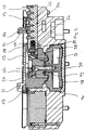
- To the magnetic chucks 1 includes a chuck body 2, which has a cylindrical basic shape and on the spindle, not shown, a machine tool can be attached.
- a total of 12 electromagnets 3 are provided, which are arranged side by side in the circumferential direction of the chuck body 2 and are aligned substantially radially to the chuck longitudinal axis.
- the electromagnets 3 are each provided with a cover 4, which define a clamping surface, as in the FIG. 2
- the electromagnets 3 are switched on and off to clamp a workpiece to be machined.
- On the clamping surface strips 5 are placed and screwed.
- the strips have radial T-slots 6, in which workpiece support elements
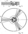
- a total of three radial guide grooves 8 are provided in the end face of the chuck body 2, which are distributed uniformly over the circumference, i. are arranged with 120 ° offset from each other.
- each centering 9 are guided radially displaceable.
- the centering jaws 9 are here formed in two parts and each consist of a base jaw 9a, which is inserted into the associated guide groove 8 and held displaceably therein, and a top jaw held on the top 9a essay jaw 9b, which protrudes beyond the clamping surface of the magnetic chuck 1 and to its radially inwardly facing end face forms a centering surface 10.
- FIGS. 5 and 6 clearly show that the base jaws 9a have on their upper side a total of five recesses 11 arranged with axial offset from each other and the top jaws 9b have on their underside a projection 12 corresponding to the recesses 11, so that the top jaws 9b at five predetermined positions on the respective Base jaw 6a can be positioned.
- the FIGS. 5 and 6 continue to show that the top jaws 9b is provided with two through holes 13 and the base jaw 9a at the webs 14 formed between the recesses 11 with corresponding threaded holes 15 through which the top jaws 9b can be screwed to the base jaws 9a.
- the centering jaws 9 can be moved together and apart by a common adjusting mechanism.
- the adjusting mechanism comprises a pneumatic cylinder 16, which isußschraupt in a central bore 17 of the chuck body 2 from the underside thereof.
- a piston 18 is inserted axially displaceable to form two pressure chambers.
- the upper end of the piston 18 passes through a through hole 19 at the top of the pneumatic cylinder 16 and is connected to a piston extension 20, screwed here.
- the piston extension 20 is held displaceably in a guide body 21, which is screwed into the central bore 17 of the chuck body 2 from the top thereof.
- the piston 18 carries in the region of the protruding from the pneumatic cylinder 16 and slidably held in the guide body 21 Piston extension 20 on its outer circumference distributed three T-shaped wedge hooks 22 which engage in corresponding T-shaped splines 23 at the radially inwardly facing end portions of the base jaws 9, the wedge surfaces of the splines 23 and the wedge hooks 22 cooperate in such a way that a Axial adjustment of the piston 18 is converted into a synchronous radial movement of the centering jaws 9.
- the piston 18 is in its lower end position, so that only the upper pressure chamber D can be seen.
- the lower pressure chamber is pressurized, so that the piston 18 is raised. If the centering jaws 9 are to be moved apart in the opposite direction, the upper pressure chamber D is pressurized and relieved the lower pressure chamber, so that the piston 18 is lowered.
- the base jaws 9a are executed axially divided and consist of a first, radially inner base jaw member 24 on which the piston 18 coupled to the keyway 22 is formed, and a radially outer second Grundbakkenelement 25 which carries the top jaws 9b.
- the two base jaw elements 24, 25 are inserted into one another.
- the outer second base jaw element 25 has at its inner end a laterally open recess 26 into which a corresponding extension 27 of the first base jaw element 24 engages.
- the connection of the two base jaw elements 24, 25 is effected by a hinge pin 28, which passes through a through hole 29 in the extension 27 of the first base jaw member 24 and fixed to the second base jaw member 25, here screwed.
- the arrangement is made such that the two base jaw members 24, 25 are guided radially in the direction of movement over the hinge pin 28 accurately, but around the axis of the hinge pin 28, which is parallel to the longitudinal axis of feed X, can be moved against each other.
- a constructive gap is provided between the base jaw elements 24, 25, so that an offset of the respective guides exerts no force on the components.
- An offset perpendicular to the feed longitudinal axis X of the guide grooves 5 is compensated for by providing a slot in the first base jaw element 24.
- a key surface not recognizable in the drawing is provided on the hinge pin 28, so that no line contact between the hinge pin 28 and the first base jaw member 24 occurs.
- the adjusting mechanism is modular, wherein it consists of a first module consisting of the pneumatic cylinder 16 and the piston 18 held therein and a second module consisting of the guide body 21 with the piston extension 20 held displaceably therein and connected to the piston extension 20 inner base jaw members 24 is formed.
- the assembly is done in a simple manner by the first module is screwed into the central bore 17 of the chuck body 2 from the underside thereof.
- the second module is inserted into the central bore 17 of the chuck body 2 from the upper side and fixed by the guide body 21 is screwed into the bore 17.
- the two modules are connected together by the piston 18 and the piston extension 20 are fixed together by the central screw 30.
- the second base jaw members 25 are inserted into the guide grooves 8 radially from the outside and the hinge pins 28 connected to the first base jaw members 24.
- the thus finished chuck is with an in FIG. 1 Cover shown 42 protected against dirt and chips.
- a component is to be clamped with the magnetic chuck 1
- this component is positioned on the workpiece support elements 7 (see FIG. 4 ) and then the piston 18 is actuated to bring the centering jaws 9 together, whereby the component is aligned centrally to the feed longitudinal axis X.
- the electromagnets 3 are turned on, so that the component is fixed to the chuck body 2.
- the centering jaws 9 can remain applied to the workpiece. However, if, for example, the centering surface of the workpiece has to be processed or the workpiece is sensitive to deformation, the centering jaws 9 can also be moved away from the workpiece.
- the stroke of the piston 18 is dimensioned so that the clamping surface can then be processed (see FIG. 3 ). However, in this case, the workpiece is no longer secured against displacement. If the workpieces are geometrically favorable, so that the holding forces of the magnetic chuck ensure a secure fixation of the workpiece, no safety measures are required. However, if the centering jaws 9 must be moved away with unfavorable workpiece geometry, the workpiece should be secured against strong displacement paths, since otherwise the workpiece or tool can be destroyed. In this case, the magnetic chuck can be equipped with alternative centering jaws 9, as shown in the FIGS. 7 to 9 are shown.
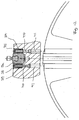
- the base jaws 9a are unchanged, however, the top jaws 9b additionally have a radially inwardly projecting extension 31, which on its upper side an upward, ie directed away from the clamping surface pin 32 carries (see FIG. 7 ). These pins serve as security elements.
- a component is to be machined in its entire circumference, as is the case for example in the inner ball bearing ring 33, as in the FIG. 9 is shown, this is positioned on the workpiece support elements 7. Subsequently, the centering jaws 9 are adjusted from their outer position to the inside, so that their centering surfaces 10 on the workpiece outside come into abutment and this center The workpiece is then magnetically fixed.
- the centering jaws 9 are moved again so far apart that a perfect processing on the tool W is possible.
- the top jaws 9b are designed so that they do not touch the workpiece 32 in this position, the pin to avoid unwanted tension on the workpiece, but are positioned with little gap and thus can prevent displacement of the workpiece in all directions.
- the base jaws 9a are inserted into the guide grooves 8 of the chuck body 2 radially outward.
- the FIGS. 10 to 15 show an alternative embodiment in which the For this purpose, the guide grooves 8 are formed so wide that the base jaws 9a can be used with the guide webs provided thereon 34 in the guide grooves 8 from the front side.
- the fixing of the base jaws 9a in the guide grooves 8 takes place by securing strips 35, which are inserted after the insertion of the base jaws 9a from the front side on both sides of the base jaws 9a in the guide grooves 8 and in each case a guide web 35 of the guide groove 8 and the corresponding guide web 34 overlap the base jaw 9a.
- the fuse strips 35 are screwed to the chuck body 2 from the bottom of the guide grooves 8 forth as in particular in the FIG. 12 is clearly recognizable.
- the guide webs 36 of the guide grooves 8 at regular intervals semicircular openings 37 and in the guide webs 34 of the base jaws 9a to the openings 37 corresponding, provided in the guide direction elongated recesses 38.
- spacers 39 are inserted, which are penetrated by fastening screws 40 which are inserted through corresponding holes 41 in the chuck body 2 below the guide grooves 8 and screwed into the fuse strips 35.
- the adjustment is determined by the length of the openings 37 in the guide webs 34 of the base jaws 9a. Specifically, the adjustment results through the length of the opening 37 less the diameter of the spacer sleeve 39.
- the formation of the through holes between the guide webs of the guide grooves 8 and the base jaws 9a allows to provide the guide jaws with a small width and thus save space. This is sufficient space for the electromagnets 3 available.
- the base jaws 9a are integrally formed in this embodiment, since it is not required. To compensate for angular misalignments between the guideways.
Landscapes
- Engineering & Computer Science (AREA)
- Mechanical Engineering (AREA)
- Jigs For Machine Tools (AREA)
Claims (10)
- Mandrin à serrage magnétique avec un corps de mandrin (2) qui présente sur son côté frontal avant une surface de serrage pour un élément de construction à fixer et avec des outils de serrage électromagnétique (3) pour la fixation d'un élément de construction sur la surface de serrage, sachant que des moyens de centrage sont prévus pour centrer un élément de construction relativement par rapport à un axe de mandrin (X) central du mandrin à serrage magnétique sur la surface de serrage entre les outils de serrage électromagnétiques (3), au moins trois rainures de guidage (8) placées avec la même déformation angulaire les unes par rapport aux autres et alignées de manière radiale par rapport à l'axe longitudinal de mandrin (X) sont formées, dans lesquelles des mors de centrage (9) sont guidés de manière radiale de manière mobile, sachant que les mors de centrage (9) peuvent être ajustés ensemble par une unité de commande, sachant que les mors de serrage (9) présentent respectivement un mors de base (9a) guidé dans le corps de mandrin (2) et un mors rapporté (9b) présentant la surface centrale, les mors rapportes (9b) formants une face de centrage à leurs surfaces intérieurs et en addition ayants une projection (31) projectante vers l'intérieure radiale, laquelle port sur son côté supérieur un pivot (32) faisant saillie vers le haut, qui lors de l'usinage externe d'une pièce à usiner, peut être positionné à proximité de sa surface interne pour sécuriser la pièce à usiner contre les déplacements.
- Mandrin à serrage magnétique selon la revendication 1, caractérisé en ce que l'unité de commande est conçue en tant que mécanisme de barre en coin, sachant que le mécanisme de barre en coin comporte des barres en coin, qui sont guidées dans des poches du corps de mandrin (2) prévues pour les mors de centrage (9) en dessous des rainures de guidage (8) et sont en prise par des engrenages correspondants ou similaires avec les mors de centrage (9).
- Mandrin à serrage magnétique selon revendication 2, caractérisé en ce que le mécanisme de barre en coin est actionné manuellement ou par une source d'énergie extérieure.
- Mandrin à serrage magnétique selon la revendication 1 ou 2, caractérisé ce que l'unité de commande est actionnée par une source d'énergie extérieure, sachant que les mors de centrage (9) sont couplés à un piston (18) réglable placé centralement dans le corps de mandrin (2) et parallèlement à l'axe longitudinal de mandrin (X), de manière à ce qu'un mouvement axial du piston (18) soit transformé en un mouvement radial des mors de centrage (9).
- Mandrin à serrage magnétique selon revendication 4, caractérisé en ce que les mors de base (9a) sont subdivisés dans leur sens longitudinal dans un premier élément de mors de base (24), qui porte un moyen d'accouplement (22) pour le raccordement avec le piston (18) et un deuxième élément de mors de base (17) qui porte le mors rapporté (6b), sachant que les deux éléments de mors de base (16, 17) sont couplés l'un avec l'autre de manière à pouvoir être ajustés et / ou basculés et / ou pivotés relativement l'un par rapport à l'autre pour l'équilibrage de tolérances de production.
- Mandrin à serrage magnétique selon revendication 5, caractérisé en ce que les deux éléments de mors de base (24, 25) sont reliés l'un à l'autre de manière à pouvoir être orientés par un axe d'articulation (28), qui est inséré dans les éléments de mors de base (24, 25) pratiquement parallèlement au sens d'axe du mandrin.
- Mandrin à serrage magnétique selon l'une des revendications 4 à 7, caractérisé en ce que le piston (18) est placé de manière amovible dans un cylindre pneumatique ou hydraulique (16), qui est logé par son côté inférieur dans un alésage central (17) du corps de mandrin (2) et y est fixé, notamment vissé à l'intérieur.
- Mandrin à serrage magnétique selon revendication 7, caractérisé en ce que le piston (18) porte sur son extrémité sortant du cylindre pneumatique ou hydraulique (16) un prolongement de piston (20) qui est relié au piston (18) de manière amovible, notamment vissé et le prolongement de piston (20) est couplé avec les mors de centrage (9).
- Mandrin à serrage magnétique selon revendication 8, caractérisé en ce que le prolongement de pison (20) est maintenu de manière mobile dans un couvercle de cylindre (21), qui est inséré par son côté supérieur dans l'alésage central (17) du corps de mandrin (2) et y est fixé, notamment vissé.
- Mandrin à serrage magnétique avec un corps de mandrin (2) qui présente sur son côté frontal avant une surface de serrage pour un élément de construction à fixer et avec des outils de serrage électromagnétique (3) pour la fixation d'un élément de construction sur la surface de serrage, sachant que des moyens de centrage sont prévus pour centrer un élément de construction relativement par rapport à un axe de mandrin (X) central du mandrin à serrage magnétique, sachant que sur la face de serrage entre les outils de serrage électromagnétique (3) sur rainures de guidage (8) aligné des manier radial par rapport à l'axe longitudinal de mandrin (X) sont formées, dans lesquelles des mors de centrage (9) sont guidés de manière radiale de manière mobile, sachant que les mors de centrage (9) peuvent être ajustés ensemble par une unité de commande, caractérisé en ce que l'unité de commande est actionnée par une source d'énergie extérieure, sachant que les mors de centrage (9) sont couplés à un piston (18) réglable placé centralement dans le corps de mandrin (2) et parallèlement à l'axe longitudinal de mandrin (X), de manière à ce qu'un mouvement axial du piston (18) soit transformé en un mouvement radial des mors de centrage (9), les mors de serrage (9) présentent respectivement un mors de base (9a) guidé dans le corps de mandrin (2) et un mors rapporté (9b) présentant la surface centrale, et les mors de base (9a) sont subdivisés dans leur sens longitudinal dans un premier élément de mors de base (24), qui porte un moyen d'accouplement (22) pour le raccordement avec le piston (18) et un deuxième élément de mors de base (17) qui porte le mors rapporté (6b), sachant que les deux éléments de mors de base (16, 17) sont couplés l'un avec l'autre de manière à pouvoir être ajustés et / ou basculés et / ou pivotés relativement l'un par rapport à l'autre pour l'équilibrage de tolérances de production.
Priority Applications (2)
| Application Number | Priority Date | Filing Date | Title |
|---|---|---|---|
| EP08005538.7A EP2105226B2 (fr) | 2008-03-25 | 2008-03-25 | Mandrin magnétique |
| AT08005538T ATE522305T1 (de) | 2008-03-25 | 2008-03-25 | Magnetspannfutter |
Applications Claiming Priority (1)
| Application Number | Priority Date | Filing Date | Title |
|---|---|---|---|
| EP08005538.7A EP2105226B2 (fr) | 2008-03-25 | 2008-03-25 | Mandrin magnétique |
Publications (3)
| Publication Number | Publication Date |
|---|---|
| EP2105226A1 EP2105226A1 (fr) | 2009-09-30 |
| EP2105226B1 EP2105226B1 (fr) | 2011-08-31 |
| EP2105226B2 true EP2105226B2 (fr) | 2016-05-25 |
Family
ID=39731456
Family Applications (1)
| Application Number | Title | Priority Date | Filing Date |
|---|---|---|---|
| EP08005538.7A Active EP2105226B2 (fr) | 2008-03-25 | 2008-03-25 | Mandrin magnétique |
Country Status (2)
| Country | Link |
|---|---|
| EP (1) | EP2105226B2 (fr) |
| AT (1) | ATE522305T1 (fr) |
Families Citing this family (14)
| Publication number | Priority date | Publication date | Assignee | Title |
|---|---|---|---|---|
| JP5431126B2 (ja) * | 2009-11-19 | 2014-03-05 | 富士機械製造株式会社 | ハイブリッド化可能な調芯機能付き高精度チャック |
| EP2383058B1 (fr) * | 2010-04-27 | 2013-04-03 | SMW-AUTOBLOK Spannsysteme GmbH | Mandrin actionné par la force |
| DE202012102578U1 (de) * | 2012-07-12 | 2013-10-14 | Röhm Gmbh | Magnetspannvorrichtung |
| DE102015113583B4 (de) | 2015-08-17 | 2018-02-01 | Schunk Gmbh & Co. Kg Spann- Und Greiftechnik | Positioniereinrichtung |
| CN109175425B (zh) * | 2018-10-09 | 2023-11-24 | 杭州泽正机械有限公司 | 一种辅助定心长行程工装夹具 |
| CN112935305A (zh) * | 2021-04-21 | 2021-06-11 | 烟台众和机床附件有限公司 | 一种专用于薄壁件加工的卡盘 |
| CN115502760A (zh) * | 2021-06-22 | 2022-12-23 | 江阴市惠尔信精密装备股份有限公司 | 用于风力发电机连接盘的加工工装 |
| US12076794B2 (en) * | 2022-03-18 | 2024-09-03 | Hammill Manufacturing Company, Co-op Tool Division | Multipurpose chuck |
| CN115780844B (zh) * | 2022-12-07 | 2025-01-07 | 宁波市镇海金海轴承有限公司 | 一种用于注塑机的钢套的夹持工装 |
| DE102023207984B3 (de) * | 2023-08-21 | 2025-01-16 | Zf Friedrichshafen Ag | Werkstückträger für einen Werkstückförderer |
| CN117226006B (zh) * | 2023-11-16 | 2024-02-13 | 山东豪迈机械制造有限公司 | 一种钢筋折弯装置 |
| CN119282770B (zh) * | 2024-12-06 | 2025-04-15 | 山东豪迈精密机械有限公司 | 一种工件装夹装置及装夹方法 |
| CN120438660A (zh) * | 2025-06-11 | 2025-08-08 | 浙江铭振电子股份有限公司 | 一种薄壁件车削大直径内孔的设备及方法 |
| CN120791466A (zh) * | 2025-09-10 | 2025-10-17 | 山东豪迈机械制造有限公司 | 一种环形薄壁类工件加工装置及加工方法 |
Family Cites Families (4)
| Publication number | Priority date | Publication date | Assignee | Title |
|---|---|---|---|---|
| US2741481A (en) * | 1954-06-14 | 1956-04-10 | Federal Mogul Bower Bearings | Rotary magnetic chuck |
| US2769642A (en) * | 1954-12-31 | 1956-11-06 | Norma Hoffmann Bearings Corp | Self-centering magnetic chuck |
| DE10049070C2 (de) * | 2000-10-02 | 2002-10-24 | Schunk Gmbh & Co Kg | Kraftspannfutter |
| ITPD20040171A1 (it) * | 2004-06-29 | 2004-09-29 | Maus Spa | Dispositivo per il bloccaggio di pezzi soggetti a lavorazioni meccaniche e macchina utensile includente detto dispositivo |
-
2008
- 2008-03-25 EP EP08005538.7A patent/EP2105226B2/fr active Active
- 2008-03-25 AT AT08005538T patent/ATE522305T1/de active
Also Published As
| Publication number | Publication date |
|---|---|
| ATE522305T1 (de) | 2011-09-15 |
| EP2105226B1 (fr) | 2011-08-31 |
| EP2105226A1 (fr) | 2009-09-30 |
Similar Documents
| Publication | Publication Date | Title |
|---|---|---|
| EP2105226B2 (fr) | Mandrin magnétique | |
| EP2559507B1 (fr) | Mandrin pouvant être actionné manuellement | |
| EP2383058B1 (fr) | Mandrin actionné par la force | |
| DE69800037T2 (de) | Spannfutter | |
| EP2566644B1 (fr) | Mandrin centré | |
| DE202008018093U1 (de) | Magnetspannfutter | |
| EP2918379B1 (fr) | Dispositif d'embrayage pour un appareil de manipulation | |
| DE102013001355B4 (de) | Spann- oder Greifeinrichtung sowie Grundbacke zur Verwendung in einer Spann- oder Greifeinrichtung | |
| EP0753368B1 (fr) | Dispositif de serrage pour la fixation relative précise de 2 pièces | |
| WO2013037458A1 (fr) | Système de serrage et corps de base, pince de serrage et outil rotatif associé, et procédé permettant d'installer l'outil rotatif dans le système de serrage | |
| DE102005031142A1 (de) | Spannvorrichtung, Grundbacken und Aufsatzbacken dafür | |
| DE202013012214U1 (de) | Verstellbare Dübellehre | |
| WO2018046036A2 (fr) | Outil d'usinage par enlèvement de copeaux multi-lames et procédé d'usinage d'un chemin laser | |
| EP2318165A1 (fr) | Outil d'usinage doté d'une plaquette de coupe réglable | |
| EP4257271A1 (fr) | Outil d'usinage par enlèvement de copeaux avec barre de guidage réglable | |
| EP0275923A2 (fr) | Dispositif de serrage de pièces | |
| DE4118376A1 (de) | Spanneinrichtung | |
| EP3509780B1 (fr) | Porte-lame et outil d'usinage par enlèvement de copeaux comportant un porte-lame | |
| EP2103367A1 (fr) | Dispositif de serrage pour objets, par exemple pour des pièces usinées devant être traitées | |
| EP3658319B1 (fr) | Outil d'usinage par enlèvement de copeaux et procédé pour l'usinage d'une roulement d'un palier | |
| DE69033337T2 (de) | Rohrendbearbeitungswerkzeug mit verbesserten Torsionreaktion und Spannmöglichkeiten | |
| DE102006052051A1 (de) | Werkzeughalter | |
| EP1862241B1 (fr) | Mandrin de serrage actionné mécaniquement | |
| EP3670045B1 (fr) | Mandrin de serrage à extension hydraulique ainsi qu'unité d'avance du forage | |
| DE3700841A1 (de) | Kupplungselement, insbesondere zum kraft- und formschluessigen verbinden eines werkzeugkopfes mit einem werkzeugtraeger |
Legal Events
| Date | Code | Title | Description |
|---|---|---|---|
| PUAI | Public reference made under article 153(3) epc to a published international application that has entered the european phase |
Free format text: ORIGINAL CODE: 0009012 |
|
| AK | Designated contracting states |
Kind code of ref document: A1 Designated state(s): AT BE BG CH CY CZ DE DK EE ES FI FR GB GR HR HU IE IS IT LI LT LU LV MC MT NL NO PL PT RO SE SI SK TR |
|
| AX | Request for extension of the european patent |
Extension state: AL BA MK RS |
|
| 17P | Request for examination filed |
Effective date: 20100304 |
|
| 17Q | First examination report despatched |
Effective date: 20100330 |
|
| AKX | Designation fees paid |
Designated state(s): AT CH DE FR IT LI |
|
| GRAP | Despatch of communication of intention to grant a patent |
Free format text: ORIGINAL CODE: EPIDOSNIGR1 |
|
| GRAS | Grant fee paid |
Free format text: ORIGINAL CODE: EPIDOSNIGR3 |
|
| GRAA | (expected) grant |
Free format text: ORIGINAL CODE: 0009210 |
|
| AK | Designated contracting states |
Kind code of ref document: B1 Designated state(s): AT CH DE FR IT LI |
|
| REG | Reference to a national code |
Ref country code: CH Ref legal event code: EP |
|
| REG | Reference to a national code |
Ref country code: DE Ref legal event code: R096 Ref document number: 502008004635 Country of ref document: DE Effective date: 20111027 |
|
| PLBI | Opposition filed |
Free format text: ORIGINAL CODE: 0009260 |
|
| PLAX | Notice of opposition and request to file observation + time limit sent |
Free format text: ORIGINAL CODE: EPIDOSNOBS2 |
|
| 26 | Opposition filed |
Opponent name: WAGNER MAGNETE GMBH & CO. KG Effective date: 20120531 |
|
| REG | Reference to a national code |
Ref country code: DE Ref legal event code: R026 Ref document number: 502008004635 Country of ref document: DE Effective date: 20120531 |
|
| PLBB | Reply of patent proprietor to notice(s) of opposition received |
Free format text: ORIGINAL CODE: EPIDOSNOBS3 |
|
| PLAB | Opposition data, opponent's data or that of the opponent's representative modified |
Free format text: ORIGINAL CODE: 0009299OPPO |
|
| R26 | Opposition filed (corrected) |
Opponent name: WAGNER MAGNETE GMBH & CO. KG Effective date: 20120531 |
|
| REG | Reference to a national code |
Ref country code: FR Ref legal event code: PLFP Year of fee payment: 9 |
|
| PUAH | Patent maintained in amended form |
Free format text: ORIGINAL CODE: 0009272 |
|
| STAA | Information on the status of an ep patent application or granted ep patent |
Free format text: STATUS: PATENT MAINTAINED AS AMENDED |
|
| 27A | Patent maintained in amended form |
Effective date: 20160525 |
|
| AK | Designated contracting states |
Kind code of ref document: B2 Designated state(s): AT CH DE FR IT LI |
|
| REG | Reference to a national code |
Ref country code: DE Ref legal event code: R102 Ref document number: 502008004635 Country of ref document: DE |
|
| REG | Reference to a national code |
Ref country code: CH Ref legal event code: AELC |
|
| REG | Reference to a national code |
Ref country code: FR Ref legal event code: PLFP Year of fee payment: 10 |
|
| REG | Reference to a national code |
Ref country code: FR Ref legal event code: PLFP Year of fee payment: 11 |
|
| P01 | Opt-out of the competence of the unified patent court (upc) registered |
Effective date: 20230628 |
|
| REG | Reference to a national code |
Ref country code: DE Ref legal event code: R081 Ref document number: 502008004635 Country of ref document: DE Owner name: SCHUNK SE & CO. KG SPANNTECHNIK GREIFTECHNIK A, DE Free format text: FORMER OWNER: SCHUNK GMBH & CO. KG SPANN- UND GREIFTECHNIK, 74348 LAUFFEN AM NECKAR, DE |
|
| PGFP | Annual fee paid to national office [announced via postgrant information from national office to epo] |
Ref country code: CH Payment date: 20250401 Year of fee payment: 18 |
|
| REG | Reference to a national code |
Ref country code: CH Ref legal event code: U11 Free format text: ST27 STATUS EVENT CODE: U-0-0-U10-U11 (AS PROVIDED BY THE NATIONAL OFFICE) Effective date: 20260401 |
|
| PGFP | Annual fee paid to national office [announced via postgrant information from national office to epo] |
Ref country code: DE Payment date: 20260319 Year of fee payment: 19 |
|
| PGFP | Annual fee paid to national office [announced via postgrant information from national office to epo] |
Ref country code: AT Payment date: 20260320 Year of fee payment: 19 |
|
| PGFP | Annual fee paid to national office [announced via postgrant information from national office to epo] |
Ref country code: IT Payment date: 20260324 Year of fee payment: 19 |
|
| PGFP | Annual fee paid to national office [announced via postgrant information from national office to epo] |
Ref country code: FR Payment date: 20260320 Year of fee payment: 19 |