EP2105253B1 - Vorrichtung zur Messung von Brillenfassungsformen - Google Patents
Vorrichtung zur Messung von Brillenfassungsformen Download PDFInfo
- Publication number
- EP2105253B1 EP2105253B1 EP09156491.4A EP09156491A EP2105253B1 EP 2105253 B1 EP2105253 B1 EP 2105253B1 EP 09156491 A EP09156491 A EP 09156491A EP 2105253 B1 EP2105253 B1 EP 2105253B1
- Authority
- EP
- European Patent Office
- Prior art keywords
- value
- measurement
- amount change
- shaft
- moving radius
- Prior art date
- Legal status (The legal status is an assumption and is not a legal conclusion. Google has not performed a legal analysis and makes no representation as to the accuracy of the status listed.)
- Ceased
Links
- 238000005259 measurement Methods 0.000 claims description 248
- 238000004364 calculation method Methods 0.000 claims description 35
- 230000033001 locomotion Effects 0.000 claims description 25
- 230000003247 decreasing effect Effects 0.000 claims description 10
- 239000011521 glass Substances 0.000 claims description 10
- 238000000034 method Methods 0.000 description 31
- 238000001514 detection method Methods 0.000 description 29
- 238000010586 diagram Methods 0.000 description 8
- 230000010354 integration Effects 0.000 description 4
- 230000003287 optical effect Effects 0.000 description 4
- 238000006073 displacement reaction Methods 0.000 description 3
- 230000005540 biological transmission Effects 0.000 description 2
- 230000026058 directional locomotion Effects 0.000 description 2
- 230000000694 effects Effects 0.000 description 2
- 238000012986 modification Methods 0.000 description 2
- 230000004048 modification Effects 0.000 description 2
- 230000010076 replication Effects 0.000 description 2
- 238000013461 design Methods 0.000 description 1
- 238000002474 experimental method Methods 0.000 description 1
- 239000000463 material Substances 0.000 description 1
Images






Classifications
-
- B—PERFORMING OPERATIONS; TRANSPORTING
- B24—GRINDING; POLISHING
- B24B—MACHINES, DEVICES, OR PROCESSES FOR GRINDING OR POLISHING; DRESSING OR CONDITIONING OF ABRADING SURFACES; FEEDING OF GRINDING, POLISHING, OR LAPPING AGENTS
- B24B9/00—Machines or devices designed for grinding edges or bevels on work or for removing burrs; Accessories therefor
- B24B9/02—Machines or devices designed for grinding edges or bevels on work or for removing burrs; Accessories therefor characterised by a special design with respect to properties of materials specific to articles to be ground
- B24B9/06—Machines or devices designed for grinding edges or bevels on work or for removing burrs; Accessories therefor characterised by a special design with respect to properties of materials specific to articles to be ground of non-metallic inorganic material, e.g. stone, ceramics, porcelain
- B24B9/08—Machines or devices designed for grinding edges or bevels on work or for removing burrs; Accessories therefor characterised by a special design with respect to properties of materials specific to articles to be ground of non-metallic inorganic material, e.g. stone, ceramics, porcelain of glass
- B24B9/14—Machines or devices designed for grinding edges or bevels on work or for removing burrs; Accessories therefor characterised by a special design with respect to properties of materials specific to articles to be ground of non-metallic inorganic material, e.g. stone, ceramics, porcelain of glass of optical work, e.g. lenses, prisms
-
- G—PHYSICS
- G01—MEASURING; TESTING
- G01B—MEASURING LENGTH, THICKNESS OR SIMILAR LINEAR DIMENSIONS; MEASURING ANGLES; MEASURING AREAS; MEASURING IRREGULARITIES OF SURFACES OR CONTOURS
- G01B5/00—Measuring arrangements characterised by the use of mechanical techniques
- G01B5/20—Measuring arrangements characterised by the use of mechanical techniques for measuring contours or curvatures
Definitions
- the present invention relates to an eyeglass frame shape-measuring apparatus that measures a lens frame shape of an eye glass frame.
- an apparatus for measuring an eyeglass frame shape is known (for reference, see JP3695988B ).
- the apparatus predicts variations of a moving radius of an unmeasured part based on changes in information of an already measured moving radius. Then the apparatus controls driving of a drive motor in correspondence to the predicted variations of the moving radius. Next, the apparatus changes a pressing pressure of a feeler that measures a shape of an eyeglass frame.
- the term "moving radius” means changes in distance from a geometrical center or optical center of the eyeglass frame to a periphery of an internal side of the eyeglass frame.
- US 2003/0105612 A1 describes an apparatus according to the preamble of claim 1.
- the present invention provides an eyeglass frame shape-measuring apparatus that measures a shape of a lens frame of a glass frame, comprising:
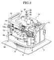
- FIG. 1 A general constitution of an eyeglass frame shape-measuring apparatus, a measuring mechanism and a slider driving mechanism of the eyeglass frame shape-measuring apparatus according to an embodiment 1 is described based on FIG. 1 through FIG. 5D .
- the eyeglass frame shape-measuring apparatus includes a main body 1.
- the main body 1 includes a case part 1a for storing a measuring mechanism situated at a lower part and a lens frame holding mechanism 1b disposed at an upper part of the case part 1a.
- a base 2 illustrated in FIG. 2 is disposed at a bottom part within the case part 1a of FIG. 1 .
- the lens frame holding mechanism 1b includes a parallel pair of guide rods 1c and 1c fixed to the case part. Besides, a pair of slide frames 3 and 3 is held in the pair of guide members 1c and 1c to be able to mutually come close or move apart from each other. The slide frames 3 and 3 mutually come close to each other in a direction and are urged in the direction by a not-illustrated coil spring or the like.
- the slide frames 3 and 3 are mutually opposed and include longitudinal walls 3a and 3a. The longitudinal walls 3a and 3a make a lens frame (not illustrated) of a glass to come into contact thereof.
- the slide frames 3 and 3 also include a lens frame holding device 3b that holds the lens frame.
- the lens frame holding device 3b includes a holding stick 3b1 of a lower part side protruded from the longitudinal wall 3a and a holding stick 3b2 of an upper side fitted on the slide frame 3 which is openable and closable from the upper side against the holding stick 3b1.
- the lens frame holding device 3b is disposed respectively against a left and a right lens frame of a not-illustrated glass.
- a constitution disclosed in, for example, JP H10-328992A or other well-known prior arts can be adopted for the lens frame holding mechanism 1b as such. Therefore, detailed descriptions of the lens frame holding mechanism 1b are abbreviated.
- a measuring mechanism 1d is disposed on the base 2.
- the measuring mechanism 1d includes a base supporting member 4 fixed on the base 2.
- a driven gear 5 of a large diameter is fitted on the base supporting member 4 and is capable of free horizontal rotations with a vertical axis as the center.
- a drive motor 6 illustrated in a frame format in FIG. 5A is mounted adjacent to the driven gear (timing gear) 5 on the base 2.
- a pinion (timing gear) 7 is fixed on an output axis 6a of the drive motor 6.
- a timing belt 8 is chained around the pinion 7 and the driven gear 5.
- a rotational base 9 is fixed in integration on the driven gear 5.
- An original point detection device for example, a photosensor 9a is fitted on the rotational base 9.
- a light emitting device 9b for indicating a position of the original point is for example disposed on the base 2.
- Line shaped or point shaped light beams are irradiated upwardly from the light emitting device 9b as a mark for the original point.
- the photo sensor 9a detects such light beams as the mark for the original point, the position of the original point of horizontal rotations of the rotational base 9 can be set.
- a transmission type photosensor and a reflection type photosensor or well known prior arts of a proximity sensor or the like can be adopted as the original point detection device.
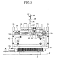
- a pair of mutually facing and parallel rail fixing plates 10 and 11 extending upwardly and downwardly is fixed in integration at both end parts of a longitudinal direction of the rotational base 9.
- end parts of a longitudinal direction of a side plate 12 are respectively fixed to a side part of the rail fixing plate 10 and a side part of the rail fixing plate 11.
- end parts of a longitudinal direction of a side plate 13 are respectively fixed to another side part of the rail fixing plate 10 and another side part of the rail fixing plate 11.
- a pair of mutually parallel and shaft shaped guide rails 14 and 14 is disposed horizontally. Both end parts of each guide rail 14 are fixed to the rail fixing plate 10 and 11. A pair of slider 15 is held to be able to move forwardly and backwardly in a longitudinal direction on guide rails 14 and 14.
- a pulley support plate part 12a protruding laterally in a horizontal direction and in close contact with the rail fixing plate 10 is shaped integrally by replication. Also on the side plate 12, a bracket 16 for motor mounting use is fixed and in close contact with the rail fixing plate 11.
- a driven pulley 17 is fitted on with a shaft line extending upwardly and downwardly as a center and capable of free horizontal rotation.
- a drive motor 18 for moving the slider is fixed.
- a DC motor or the like is used as the drive motor 18.
- an output shaft 18a of the drive motor 18 has a shaft line directed upwardly and downwardly.
- a drive pulley 19 is fitted onto the output shaft 18a.
- a circular shaped wire 20 is chained around both pulleys 17 and 19. A part in the vicinity of one end part of the wire 20 is held by a shaft shaped wire holding member 21.
- the wire holding member 21 is fixed to the slider 15 via brackets 22 and 22'.
- both end parts of the wire 20 are connected via a coil spring 23. Therefore, when the drive motor 18 is rotated normally or reversely, the drive shaft 18a and the drive pulley 19 are rotated normally or reversely so that the slider 15 is moved leftward or rightward within the FIG. 3 .
- an original point sensor 20a for detecting an original point of a movement position (movement amount) of the slider 15 is interposed.
- a reflective type sensor or the like is for example used as the original point sensor 20a.
- the original point sensor 20a includes a reflective plate 20b in which a slit shaped reflective surface (not illustrated) extending upwardly and downwardly is disposed.
- the original point sensor also includes a reflective type photosensor 20c having a light emitting device and a light receiving device.
- the reflective plate 20b is disposed on the bracket 22'.
- the photosensor 20c is disposed on the side plate 12.
- well known prior arts such as a transmission type photosensor and a proximity sensor or the like can be adopted as the original point sensor 20a.
- a supporting plate part 13a protruding laterally in a horizontal direction is integrally shaped by replication.
- a linear scale 24 is interposed as a moving radius detection sensor that detects positions of horizontal directional movements of the slider 15 which moves towards an extending direction of the guide rail 14.
- the linear scale 24 includes a shaft shaped main scale 25 held by the slider 15 to be parallel to the guide rail 14 and a detection head 26 fixed to the supporting plate part 13a that reads out positional information of the main scale 25.
- the detection head 26 detects positions of horizontal directional movements of the slider 15 from information of the main scale 25 for positional detection use (information for movement amount detection use).
- a well known magnetic type or optical type linear scale can be used as the linear scale 24.
- a magnetic pattern of magnetic poles S, N is disposed alternatively at minute intervals in a shaft line direction of the main scale 25 as information for positional detection use (information for movement amount detection use).
- the detection head 26 a head for detecting magnetic changes so that a movement amount (a movement position) of the slider 15 can be detected.
- the main scale 25 is formed into a plate shape and slits of a minute interval are disposed in a longitudinal direction of this main scale 25.
- a light emitting device and a light receiving device are disposed so that the main scale 25 is interleaved in-between. Then light from the light emitting device is detected by the light receiving device via slits of the main scale 25.
- a movement amount (a movement position) of the slider 15 can be detected by calculating the number of slits.
- a through hole 15a is formed, as illustrated in FIG. 2 , on an approximately central part of the slider 15.
- a guide barrel 27 extending upwardly and downwardly is inserted through the through hole 15a.
- a supporting frame 28 is disposed, as illustrated in FIG. 4 , at a lower side of the slider 15.
- the supporting frame includes longitudinal frames 29 and 30 with their upper end parts held by the slider 15 and a lateral plate (bottom plate) 31 fixed to lower end parts of the longitudinal frames 29 and 30.
- a constitution of the elevator mechanism and a constitution of the feeler of the eyeglass frame shape-measuring apparatus of the embodiment 1 are described based on FIG. 6 through FIG. 10 .
- lower end parts of a pair of shaft shaped supporting members 32 and 32 disposed mutually parallel and extending upwardly and downwardly are fixed to the lateral plate (bottom plate) 31.
- a holding member 33 is fixed to upper end parts of these supporting members 32 and 32.
- a longitudinal wall 34a of a guide supporting member 34 with an "L" letter shaped side surface formed thereof is fixed to the holding member 33.
- a lower end part of the guide barrel 27 is fixed onto a lateral wall (superior wall) of the guide supporting member 34.
- a feeler shaft 35 extending upwardly and downwardly is fitted into the guide barrel 27 and held thereby with free capability of upward and downward movement.
- a feeler mounting member 36 is disposed integrally on an upper end part of the feeler shaft 35.
- the feeler mounting member 36 is "L" letter shaped to include a mounting part 36a fitted vertically onto the upper end part of the feeler shaft 35 and a vertical part 36b extending upwardly from the mounting part 36a.
- a feeler 37 for a lens frame is disposed integrally on an upper end part of the vertical part 36b and parallel to the mounting part 36a
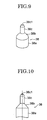
- a feeler 38 for a lens frame protruding upwardly is disposed integrally on an upper end of the feeler mounting member 36.
- the feeler 38 for the lens frame includes a shaft shape-measuring part 38a fitted on the upper end of the vertical part 36b of the feeler mounting member 36 and parallel to a shaft line of the feeler shaft 35, a tapered part 38b that tapers off to a point and disposed on an upper end part of the shaft shape-measuring part 38a and a shaft part 38c with an engaging hole of a small diameter provided in a coupled manner to an upper end of the tapered part 38b.
- an upper end (pointy end) part of the shaft part 38c with the engaging hole is half spherical shaped. A pointy end 38c1 thereof matches a shaft line of the shaft shape-measuring part 38a.
- a bracket 39 is fixed to a lower end part of the feeler shaft 35.
- the linear scale 40 includes a shaft shaped main scale 41 disposed parallel to the feeler shaft 35 in an upward and downward direction and a detection head 42 that detects a position of a movement of the feeler 37 and the feeler 38 towards an upward and downward direction from an amount of movement by the main scale 41 in an upward and downward direction.
- An upper end part of the main scale 41 is fixed to the holding member 33.
- a lower end part of the main scale 41 is fixed to (or held by) the bracket 39.
- the detection head 42 is held by the holding member 33.
- a magnetic type or an optical type linear scale can be adopted as the linear scale 40.
- a coil spring 43 is interposed between the bracket 39 and the lateral plate (bottom plate) 31 to urge the feeler shaft 35 upwardly by a spring. Furthermore, an engaging shaft 44 is fitted in the vicinity of the lower end part of the feeler shaft 35. The engaging shaft 44 is situated upward to the bracket 39 and orthogonal to the feeler shaft 35.
- a bracket 45 formed with a "U" character shape is fixed on the lateral plate (bottom plate) 31. Both end parts of a supporting shaft 46 is held on opposing walls 45a and 45a of the bracket 45 and capable of free rotation around a shaft line. A hold down lever 47 is fixed onto the supporting shaft 46.
- the hold down lever 47 comes into contact with an upper part of the engaging shaft 44.
- a tension coil spring 48 for pulling down the lever is interposed between the hold down lever 47 and the lateral plate 31.
- a tension spring force of the tension coil spring 48 is set to be larger than a spring force of the coil spring 43.
- a lever 49 for controlling an elevation position is fixed on the supporting shaft 46.
- the lever 49 controls an elevation position of the engaging shaft 44 elevated by the hold down lever 47.
- the lever 49 is used for setting an elevation position of the feeler shaft 35 and the feeler 37 for a lens frame as well as an elevation position of the feeler 38 for the lens frame.
- the lever 49 for controlling an elevation position is extended in a same direction as the hold down lever 47.
- an actuator motor 50 is disposed on a lower side of the lever 49 for controlling an elevation position.
- the actuator motor 50 includes a motor main body 50a fixed to the lateral plate 31.
- the actuator motor 50 also includes a shaft 51 protruding towards an upside from the motor main body 50a and disposed with its shaft line parallel to the feeler shaft 35.
- a position control lever 49 comes into contact with an upper end of the shaft 51 by the tension spring force of the tension coil spring 48.
- a DC motor or the like is used as the actuator motor 50.
- the shaft 51 advances upwardly.
- the actuator motor is rotated reversely, the shaft 51 moves downwardly.
- the coil spring 43, the supporting shaft 46, the hold down lever 47, the tension coil spring 48, the lever 49 for controlling an elevation position and the actuator motor 50 or the like constitute the elevator mechanism of the feeler 37 and the feeler 38.
- FIG. 10A A constitution of the system for measurement, driving and calculation control in the eyeglass frame shape-measuring apparatus of the embodiment 1 is described based on FIG. 10A hereinbelow.
- a detection signal from the photosensor 9a of an original point position corresponding to a horizontal position of the rotational base 9 and a detection signal from the photosensor 20c of an original point position corresponding to a movement of the slider 15 are inputted to a calculation control circuit 52.
- a detection signal of a slider movement amount from the detection head 26 of the linear scale 24 and a detection signal of a Z shaft movement amount from the detection head 42 of the linear scale 40 are inputted to the calculation control circuit 52.
- a holder detection device 53 is disposed on a side wall of the slide frame 3 and 3 situated at one side.
- a micro switch or the like is used for the holder detection device 53.
- a detection signal from the holder detection device 53 is inputted to the calculation control circuit 52.
- a switch signal from a start switch 54 for starting measurement is also inputted to the calculation control circuit 52.
- the calculation control circuit 52 includes a motor drive circuit which converts a control command value to a motor drive current.
- the calculation control circuit 52 in correspondence to the control command value, drive-controls the drive motor 6 that drives the rotational base 9, the drive motor 18 for use in the above described slider movement and the actuator motor 50 that moves the feeler 37 and the feeler 38 upwardly and downwardly within a control range of an elevation position.
- a memory 55 for recording necessary data is connected to the calculation control circuit 52 to be capable of reading out writings.
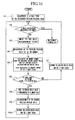
- FIG. 11 is a flow chart that illustrates a flow of a control process implemented in the calculation control circuit 52 that measures and calculates a lens frame shape of the eyeglass frame shape-measuring apparatus of the embodiment 1.
- a control device for measuring and calculating a lens frame shape a control device for measuring and calculating a lens frame shape.
- a switch signal is inputted from a start switch 54 for starting measurement.
- a moving radius value and a Z shaft value at a first point that is, a first measurement point are measured at a preliminarily set prescribed pressing pressure value and then the control process proceeds to step S2.
- the "prescribed pressing pressure value” is set according to a measurement speed.
- the faster the speed the larger is a resistance to a movement during a slide movement so that the higher the pressing pressure value is applied by the feeler 37 for a lens frame pressing against a lens frame.
- the "preliminarily set prescribed pressing pressure" is set to a value of a comparatively faster part of the measurement speed because as many lens frames as possible need to be measured in a short period of time.
- the measurement speed is slowed in correspondence in the case where the prescribed pressing pressure value is too high.
- step S2 in continuation to the measurement of the first point at the step S1, it is determined whether a measurement of a moving radius and a Z shaft value around a whole circumference of the lens frame is over or not. In the case of YES (the whole circumference measurement is over), the control process switches over to measurement termination. In the case of NO (the whole circumference measurement is not over), the control process switches over to a step S3.
- step S3 in continuation to the determination in the step S2 of the whole circumference measurement being not over, rotation is performed for a portion of a prescribed amount and movement to a next measurement point is performed.
- the control process then switches over to a step S4.
- moving to the next measurement point it is moved at a pressing pressure value set a previous time.
- step S4 in continuation to moving to the next measurement point in the step S3, a moving radius value and a Z shaft value are measured at the pressing pressure value set the previous time.
- the control process then switches over to a step S5.
- an amount change of a moving radius value is calculated from a measured moving radius value and an already measured moving radius value.
- an amount change of a Z shaft value is calculated from a measured Z shaft value and an already measured Z shaft value.
- the control process then switches over to a step S6.
- the calculation method of the amount change of the moving radius value and the amount change of the Z shaft value can be a comparison between the value measured at the step S4 and a value just before the value measured at the step S4 or a comparison between all measurement values extended back to a few points before including the value measured at the step S4 and an average value of any a few points already measured previously.
- the value of the amount change (the moving radius value and the Z shaft value) can be represented directly by a difference of numerical values or calculated as a slope.
- step S6 in continuation to the calculations of the amount change of the moving radius value and the amount change of the Z shaft value in the step S5, the amount change calculated in the step S5 is compared to a preliminarily set prescribed value (a target value for comparison).
- a target value for comparison a target value for comparison
- the control process switches over to a step S7.
- the control process switches over to a step S8.
- a comparison is made between the amount change of the moving radius value and a prescribed value of the amount change of the moving radius value.
- Another comparison is made between the amount change of the Z shaft value and another prescribed value of the amount change of the Z shaft value.
- the control process switches over to the step S7 in which a pressing pressure value is not changed.
- the control process then switches over to the step S8 in which the pressing pressure value is changed.
- step S7 in continuation to the determination in the step S6 that the amount changes are less than the prescribed values, the moving radius value and the Z shaft value measured at the step S4 are recorded together with a rotational angle information that indicates a measurement point.
- the control process then returns to the step S2.
- step S8 in continuation to the determination in the step S6 that the amount change is greater than or equal to the prescribed value, increasing or decreasing directions of the moving radius value and the Z shaft value are determined.
- a pressing pressure value is reset in correspondence to a size of the amount change.
- the control process then switches over to a step S9.
- a case in which the pressing pressure value exceeds an optimum value (or optimum range) leads to a deformation of the frame.
- a case in which the pressing pressure value is less than the optimum value (or optimum range) leads to a drop off of the feeler during a measurement. Therefore, the pressing pressure value is controlled to an optimum value.
- optimum value data is obtained preliminarily by an experiment or the like.
- a pressing pressure value table is developed from the optimum value data.
- the pressing pressure value table is preliminarily recorded in a memory that is capable of writing.
- a change of the pressing pressure value by resetting is performed by a change in measurement speed in which the measurement speed is slowed. Therefore, the pressing pressure value table developed using the optimum value is set in detail using a combination of the amount change of the moving radius value, the increasing or decreasing directions of the moving radius value and the measurement speed.
- the pressing pressure value table developed using the optimum value is set in detail also using a combination of the amount change of the Z shaft value, the increasing or decreasing directions of the Z shaft value and the measurement speed.
- the measurement speed is selected based on the respective amount change, the respective change direction and the respective pressing pressure value table (when one measurement speed is calculated, the one measurement speed is selected, when two measurement speeds are calculated, the slower measurement speed is selected).
- the selected measurement speed becomes the pressing pressure value by resetting.
- step S9 in continuation to resetting in the step S8 the pressing pressure value in correspondence to the amount change, a moving radius value and a Z shaft value of a measurement point with the amount change determined to be greater than or equal to the prescribed value are measured again using the reset pressing pressure value.
- the control process then switches over to a step S 10. That is, in the step S6, in the case the amount change is determined to be greater than or equal to the prescribed value, then the eyeglass frame can be considered to be easily deformable so that measurement speed thereafter is set to be slow.
- step S10 in continuation to the re-measuring in the step S9 using a changed pressing pressure value, the re-measured moving radius value and Z shaft value are recorded together with information of a rotational angle that indicates a measurement point.
- the control process then returns to the step S2.
- the operations of the eyeglass frame shape-measuring apparatus of the embodiment 1 are classified into, firstly, “preparatory operations of a lens frame shape measurement”, secondly, “operations of a lens frame shape measurement of a not easily deformable glass frame” and thirdly, “operations of a lens frame shape measurement of an easily deformable glass frame” and described according to the classifications.
- the upper end of the shaft 51 of the actuator motor 50 should be set to a lowest end position (bottom dead point).
- the hold down lever 47 is rotatably urged by the tension coil spring 48 with a stronger spring force than the coil spring 43 to rotate with the supporting shaft 46 as the center towards a lower side.
- the hold down lever 47 pushes down the feeler shaft 35 towards the lower side via the engaging shaft 44.
- the feeler 37 for a lens frame and the feeler 38 for a lens frame are set to lowest end positions.
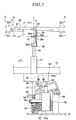
- an eyeglass frame MF having a left lens frame LF and a right lens frame RF is disposed between the slide frame 3 and 3 of FIG. 1 (illustration of the eyeglass frame MF is abbreviated in FIG. 1 ) so that the lens frame LF (RF), as illustrated in FIG. 7 , is sandwiched between the holding stick 3b1 and 3b2. This holding is the same to that of JP H10-328992A .
- the photosensor 9a detects an original point of a horizontal rotation of the rotational base 9 from light beams emitted from the light emitting device 9b. Besides, the original point sensor 20a detects an original point of a movement position of the slider 15.
- a holding part held by the holding stick 3b1 and 3b2 of the lens frame is set to a lowest height in comparison to other parts.
- a height of a V-shaped groove Ym of the lens frame LF(RF) also becomes the set height which is a position B for starting lens frame shape measurement.
- the calculation control circuit 52 rotates normally the actuator motor 50 and makes the shaft 51 to proceed upwardly for a predetermined amount (move-up) from the position illustrated in FIG. 6 through FIG. 8 .
- the shaft 51 lifts upwardly for a predetermined amount a free end part of the lever 49 for controlling an elevation position against the spring force of the tension coil spring 48.
- the hold down lever 47 rotates integrally with the supporting shaft 46 with its free end part moving upwardly for a predetermined amount. Due to the move up of the free end part of the hold down lever 47, the engaging shaft 44 is moved upwardly by the spring force of the coil spring 43 tracking the free end part of the hold down lever 47 so that the feeler shaft 35 is moved upwardly for a predetermined amount.
- the upward moving amount of the feeler shaft 35 is equal to an amount L in which a tip end of the feeler 37 for the lens frame moves upwardly from the initial position ( ⁇ ) to a height ( ⁇ ) facing a V-shaped groove Ym of the above described position B for starting shape measurement.
- the calculation control circuit 52 drive controls the drive motor 18 to rotate the drive pulley 19 and move the slider 15 along the guide rail 14 by the wire 20 illustrated in FIG. 2 and FIG. 5B .
- the slider 15 is moved in a direction of an arrow A1 of FIG. 7 .
- This movement is performed until the tip end of the feeler 37 for the lens frame comes into contact with the V-shaped groove Ym at the position B for starting shape measurement.
- the feeler 37 for the lens frame actually elastically comes into contact with the V-shaped groove Ym by the spring force of the coil spring 23.
- the drive motor 18 is stopped in such a state.
- the calculation control circuit 52 furthermore rotates normally the actuator motor 50 and makes the shaft 51 to proceed upwardly for a predetermined amount (move-up). At this moment, the shaft 51 lifts upwardly for a predetermined amount the free end part of the lever 49 for controlling an elevation position against the spring force of the tension coil spring 48.
- the hold down lever 47 rotates integrally with the supporting shaft 46 with its free end part moving upwardly for a predetermined amount.
- the free end part of the hold down lever 47 is seceded from the engaging shaft 44 for a predetermined amount so that the feeler shaft 35 becomes possible to move in an upward and downward direction (Z shaft direction).
- the calculation control circuit 52 drive-controls the drive motor 6 and rotates normally the drive motor 6.
- the rotation of the drive motor 6 is transferred to the driven gear 5 via the pinion 7 and the timing belt 8 so that the driven gear 5 is rotated horizontally in integration to the rotational base 9 (refer to FIG. 5A ).
- the slider 15 and a number of parts disposed on the slider 15 rotate horizontally in integration to the rotational base 9. Besides, the tip end of the feeler 37 for the lens frame moves in sliding contact along the V-shaped groove Ym.
- rotational operations of the rotational base 9 are an intermittent rotation that repeats rotations of a portion of a prescribed amount according to a set measurement speed and divides a whole circumference of the V-shaped groove to a plurality of measurement points. Then the tip end of the feeler 37 for the lens frame is pressure pressed to the V-shaped groove Ym at each measurement point while a moving radius value pn and a Z shaft value Zn are measured so that together with a rotational angle ⁇ n, three dimensional lens frame shape information ( ⁇ n , pn, Zn) is obtained and the lens frame shape is measured.
- the moving radius value pn is a distance from a moving radius center O to an edge of an internal side of a frame trim (refer to FIG. 12 ).
- the Z shaft value Zn is a displacement amount of the moving radius center O of a direction orthogonal to the moving radius direction (refer to FIG. 13 ).
- Such an eyeglass frame has a property such that even if whole circumference measurement is performed at a prescribed pressing pressure value set by values of a comparatively faster side of measurement speed, an amount change of a moving radius value and an amount change of a Z shaft value can be suppressed to below the prescribed value.
- a measurement process proceeds in an order of step S1 ⁇ step S2 ⁇ step S3 ⁇ step S4 ⁇ step S5 ⁇ step S6 ⁇ step S7.
- step S7 a moving radius value ⁇ 1 of the first point and a Z shaft value Z1 are recorded together with a rotational angle ⁇ 1 that indicates the measurement point.
- step S7 a process flow that proceeds in an order of step S2 ⁇ step S3 ⁇ step S4 ⁇ step S5 ⁇ step S6 ⁇ step S7 is repeated for the number of set measurement points while a fast measurement speed due to the preliminarily set prescribed pressing pressure value is maintained.
- step S7 a moving radius value pn and a Z shaft value Zn of each point are recorded together with a rotational angle ⁇ n that indicates a measurement point.
- the measurement process proceeds from the step S2 to an end of measurement so that the lens frame shape measurement is terminated.
- the slider 15 moves along the guide rail 14 and integrally with the feeler 37 for the lens frame. Therefore, a movement amount of the slider 15 when the slider 15 is moved from an original point position is the same to a movement amount of a tip end of the feeler 37 for the lens frame.
- the movement amount is calculated by the calculation control circuit 52 from a detection signal of the detection head 26 of the linear scale 24. Besides, a dimension (length) from a center of the feeler shaft 35 to the tip end of the feeler 37 for the lens frame is already known.
- a rotational angle ⁇ n of the rotational base 9 due to rotations of the drive motor 6 is calculated from a driving pulse number of the drive motor 6 and a moving radius value pn corresponding to the rotational angle ⁇ n is calculated so that shapes of a circumferential direction of the V-shaped groove Ym of the lens frame LF(RF) (lens frame shape) can be calculated as lens frame shape information ( ⁇ n, pn) of a circular cylindrical coordinates format.
- the tip end of the feeler 37 for the lens frame moves in sliding contact along the V-shaped groove Ym
- the lens frame LF(RF) is curved in upward and downward directions
- the curved state towards the upward and downward directions is calculated by the calculation control circuit 52 from a detection signal of the detection head 42 of the linear scale 40 as a displacement amount in upward and downward directions.
- the displacement amount towards the upward and downward directions becomes the Z shaft value Zn.
- the whole circumference measurement can be finished at a prescribed pressing pressure value in which a value of a side of a comparatively fast measurement speed is adopted so that three dimensional lens frame shape information ( ⁇ n, ⁇ n, Zn) of a lens frame shape of the lens frame LF(RF) can be obtained in a short time.
- FIG. 12 is a functional schematic diagram that illustrates measurement operations of a moving radius value within measurement of a lens frame shape of an easily deformable eyeglass frame by the eyeglass frame shape-measuring apparatus of the embodiment 1.
- FIG. 13 is a functional schematic diagram that illustrates measurement operations of a Z value within measurement of a lens frame shape of an easily deformable eyeglass frame by the eyeglass frame shape-measuring apparatus of the embodiment 1.
- JP3695988B as a conventional eyeglass frame shape-measuring apparatus, a method is known to predict moving radius changes of a non-measured part and control a drive motor so that a pressing pressure can be changed.
- this method is fine in the case if the moving radius of the unmeasured part changes as predicted.
- the moving radius changes in a direction that differs from prediction there are cases in which the moving radius changes in a direction that differs from prediction. In such cases, it is possible that the pressing pressure changes in a direction that reversely deforms the eyeglass frame so that shape measurement is not correctly done.
- the measurement speed must be set slower by judgments of a measurer so that operations become burdensome.
- the inventors of the present invention propose the eyeglass frame shape-measuring apparatus of the embodiment 1 in correspondence to the above requirements. For example, in the case a whole circumference measurement needs to be performed for an easily deformable eyeglass frame of a thin rim or the like at a prescribed pressing pressure value in which a value of a side of a comparatively fast measurement speed is adopted, operations of the lens frame shape measurement of the eyeglass frame are described hereinbelow in which amount changes of a moving radius value and amount changes of a Z shaft value are suppressed to below the prescribed value.
- a measurement process proceeds in an order of step S1 ⁇ step S2 ⁇ step S3 ⁇ step S4 ⁇ step S5 ⁇ step S6 ⁇ step S7.
- step S7 a moving radius value ⁇ 1 of the first point and a Z shaft value Z1 are recorded together with a rotational angle ⁇ 1 that indicates the measurement point.
- step S7 a measurement process flow that proceeds in an order of step S2 ⁇ step S3 ⁇ step S4 ⁇ step S5 ⁇ step S6 ⁇ step S7 is repeated until the measurement of the (m-1) point is over while a fast measurement speed due to the preliminarily set prescribed pressing pressure value is maintained.
- step S7 a moving radius value of each point ( ⁇ 2, ..., ⁇ m-1) and a Z shaft value of each point (Z2, ..., Zm-1) are recorded together with a rotational angle ( ⁇ 2, ..., ⁇ m-1) that indicates a measurement point.
- the measurement process enters a measurement of a (m) point.
- the measurement process proceeds in an order of step S2 ⁇ step S3 ⁇ step S4 ⁇ step S5 ⁇ step S6.
- a comparison is made between an amount change of a moving radius value (for example,
- a Z shaft value for example,
- the measurement process then proceeds from the step S6 towards a step S8 ⁇ a step S9 ⁇ a step S10.
- step S8 increasing or decreasing directions of the moving radius value and the Z shaft value are determined and a pressing pressure value is reset in correspondence to the size of the amount change.
- step S9 using the reset pressing pressure value, a moving radius value ⁇ m and a Z shaft value Zm of a measurement point (point m or the (m)th point) with the amount change determined to be greater than or equal to the prescribed value are re-measured.
- the re-measured moving radius value ⁇ m and the Z shaft value Zm are recorded together with a rotational angle ⁇ m that indicates a measurement point.
- the measurement process returns to the step S2 in which the measurement speed is slowed by the pressing pressure value reset in the step S8.
- the measurement process then proceeds in an order of step S2 ⁇ step S3 ⁇ step S4 ⁇ step S5 ⁇ step S6.
- measurement of a (m+1)th point is performed at the step S4.
- the measurement speed remains slowed according to the pressing pressure value reset at the step S8, with reference to the flow chart illustrated in FIG.
- step S7 a measurement process flow that proceeds from step S2 ⁇ step S3 ⁇ step S4 ⁇ step S5 ⁇ step S6 ⁇ step S7 is repeated until the measurement of the final point is finished.
- step S7 a moving radius value of each point ( ⁇ m+1, ..., ⁇ n) and a Z shaft value of each point (Zn+1, ..., Zn) are recorded together with a rotational angle ( ⁇ m+1, ..., ⁇ n) that indicates a measurement point.
- a comparison is made between an actual measurement value, that is, an amount change of a moving radius value and a prescribed value of the amount change of the moving radius value.
- Another comparison is made between an actual measurement value, that is, an amount change of a Z shaft value and a prescribed value of the amount change of the Z shaft value.
- shape measurement is performed at a comparatively fast measurement speed SP1 according to the preliminarily set prescribed pressing pressure value.
- the measurement speed is automatically switched over to a measurement speed SP2 slower than the first measurement speed SP1 so that moving radius values are measured at the measurement speed SP2 from the moving radius value ⁇ m of the (m)th point until the moving radius value pn of the final point.
- the comparison is made between the amount change of the moving radius value and the prescribed value of the amount change of the moving radius value.
- the another comparison is made between the amount change of the Z shaft value and the prescribed value of the amount change of the Z shaft value.
- the eyeglass frame shape-measuring apparatus of the embodiment 1 can obtain the effects listed hereinbelow.
- the eyeglass frame shape-measuring apparatus of the present invention is described above based on the embodiment 1 but the specific constitutions are not limited to the embodiment 1. Design modifications and changes are allowed as long as they do not deviate from the scope of the invention set in each of the claims.
- an example of changing the measurement speed by the drive motor 6 is illustrated as an embodiment of the changes of the pressing pressure value.
- an example of changing a motor torque of the drive motor 6 can be adopted.
- Another example of changing simultaneously the motor torque of the drive motor 6 and the measurement speed can also be adopted.
- an example can be adopted in which the spring force applied to press the feeler 37 for the lens frame towards the lens frame can be changed by operations of the actuator.
- the frame shape value re-measurement part (step S9) of the control device ( FIG. 11 ) for measurement and calculation of the shape of the lens frame re-measures the frame shape value of the measurement point with the amount change determined to be greater than or equal to the prescribed value.
- the point to be measured can return to couple points before where re-measurement can be started from the couple points before under a state in which the measurement speed is slowed.
- the point to be measured can return to the first point where re-measurement can be started from the first point under a state in which the measurement speed is slowed.
- the initial setting part for the prescribed pressing pressure value of the control device ( FIG. 11 ) for measurement and calculation of the shape of the lens frame performs initial settings of the prescribed pressing pressure value. That is, when starting lens frame shape measurement, the prescribed pressing pressure value is initially set to a comparatively high measurement speed in which the duration of the measurement terminates in a short time.
- the initial prescribed pressing pressure value is provided by a switch-over setting by a manual operation.
- partial preparatory measurements of one point through couple points are performed. Based on deformation information by the preparatory measurements, the initial prescribed pressing pressure value is provided by the manual switch-over setting or an automatic switch-over setting.
- an example is illustrated in which the frame shape value of any one point of the eyeglass frame is measured once and compared to an already measured frame shape value to detect shape deformations of the eyeglass frame.
- an example can be adopted to include a detection device that measures a plurality of times any one point of the eyeglass frame so that changes of the moving radius at the measurement points and shape deformations of the eyeglass frame can be detected.
- the eyeglass frame shape-measuring apparatus of the present invention when measuring the lens frame shape, a whole circumference of the lens frame shape is divided into a plurality of measurement points.
- the frame shape values at each measurement point measured by moving the feeler for the lens frame so that the feeler is in sliding contact along the lens frame shape are obtained as frame shape information.
- a comparison between the frame shape value at one measurement point and another already measured frame shape value is made in the control device for measurement and calculation of the shape of the lens frame.
- a pressing pressure value is determined in correspondence to the amount change of the frame shape detected at the one measurement point.
- this pressing pressure value differs from a preliminarily set pressing pressure value
- the pressing pressure value is reset and frame shape is re-measured at the already measured measurement point.
- deformation of the frame shape is determined at each measurement point based on the actual measurement values and even in the case where the frame shape changes in a direction that differs from prediction, measurement of the lens frame shape of the eyeglass frame can be performed precisely.
Landscapes
- Engineering & Computer Science (AREA)
- Physics & Mathematics (AREA)
- General Physics & Mathematics (AREA)
- Chemical & Material Sciences (AREA)
- Ceramic Engineering (AREA)
- Inorganic Chemistry (AREA)
- Mechanical Engineering (AREA)
- A Measuring Device Byusing Mechanical Method (AREA)
- Eyeglasses (AREA)
- Length Measuring Devices With Unspecified Measuring Means (AREA)
Claims (7)
- Vorrichtung zum Messen von Brillenfassungsformen, mit der sich eine Form einer Brillenglasfassung messen lässt und die aufweist:einen Abtaster (37) für eine Brillenglasfassung, der ausgeführt ist, eine Richtung eines sich bewegenden bzw. eines laufenden Radius einer Brillenglasfassung zu messen;einen Antriebsmotor (6), der ausgeführt ist, den Abtaster (37) für die Brillenglasfassung mit einer bestimmten, zu dieser hin gerichteten Andruckkraft zu beaufschlagen;eine Steuereinrichtung zum Messen und Berechnen der Form der Brillenglasfassung, mit der der Gesamtumfang der Form des Brillenglasrahmens zu einer Vielzahl von Messpunkten unterteilbar ist; für den sich bewegenden bzw. laufenden Radius einen Radiuswert sowie einen Wert eines Z-Schafts messbar ist, die rechtwinklig zur Richtung des laufenden Radius liegen, und dies an jedem Messpunkt, während der Abtaster (37) für die Brillenglasfassung diese entlang läuft; und der laufende Radiuswert und der Wert des Z-Schafts sich als Information der Fassungsform gewinnen lassen; wobeidie Steuereinrichtung einen Größenänderungs-Vergleichsteil aufweist, mit dem der laufende Radiuswert und der Wert des Z-Schafts an einem Messpunkt mit dem bereits erfassten laufenden Radiuswert und dem Wert des Z-Schafts an einem bereits erfassten Messpunkt vergleichbar sind; das Ausmaß der Änderung des laufenden Radiuswerts und dem Wert des Z-Schafts an dem einen Messpunkt berechenbar ist und die berechnete Änderung des laufenden Radiuswerts und des Wertes des Z-Schafts jeweils mit einem vorgeschriebenen bzw. Sollwert vergleichbar sind;dadurch gekennzeichnet, dass mit der Steuereinrichtung der Wert der Andruckkraft entsprechend der Änderung des laufenden Radiuswert und dem Wert des Z-Schafts neu einstellbar ist, falls die im Änderungs-Vergleichsteil berechnete Änderung des laufenden Radiuswerts und dem Wert des Z-Schafts jeweils gleich dem oder größer als der Sollwertwert ist; der laufende Radiuswert und der Wert des Z-Schafts am bereits erfassten Messpunkt auf Grund der verstellten Andruckkraft erneut messbar ist; und der erneut gemessene laufende Radiuswert und der erneut gemessene Wert des Z-Schafts aufzeichenbar sind; wonach, falls die Messung des gesamten Umfangs noch nicht abgeschlossen ist, zum nächsten Messpunkt übergegangen wird.
- Vorrichtung zum Messen von Brillenglas-Fassungsformen nach Anspruch 1, bei der:mit der Steuereinrichtung zum Messen und Berechnen der Form der Brillenglasfassung der bereits gemessene laufende Radiuswert und der Wert des Z-Schafts aufzeichenbar sind, falls die an dem einen Messpunkt erfasste Änderung des laufenden Radiuswerts und des Werts des Z-Schafts geringer ist als der jeweilige Sollwert; und der Abtaster bei erhaltener, momentan eingestellter Andruckkraft zum nächsten Messpunkt weiterführbar ist; undmit der Steuereinrichtung bei erhaltener nachgestellter Andruckkraft der Abtaster zum nächsten Messpunkt weiterführbar ist, falls die Änderung des laufenden Radiuswerts und des Werts des Z-Schafts an dem einen Messpunkt jeweils gleich oder größer als der Sollwert ist.
- Vorrichtung zum Messen der Brillenglas-Fassungsform nach Anspruch 2, bei der:mit dem Vergleichsteil einer Größenänderung beim Bewegen des Abtasters zum Messpunkt der laufende Radiuswert und der Wert des Z-Schafts durch die momentanen Andruckkraft messbar sind.
- Vorrichtung zum Messen der Brillenglas-Fassungsform nach Anspruch 2 oder 3, bei der:Einstelländerungen der Andruckkraft in der Steuereinrichtung zum Messen und Berechnen der Form der Brillenglasfassung Einstellungen sind, die Änderungen der Messgeschwindigkeit entsprechen; unddie Steuereinrichtung weiterhin einen Nachstellteil für die Andruckkraft aufweist, der die Messgeschwindigkeit entsprechend der Größe der Änderung des laufenden Radius und des Werts der Z-Achse ändert, wenn die Änderung des laufenden Radius und des Werts der Z-Achse des einen Messpunkt gleich oder größer als der Sollwert ist.
- Vorrichtung zum Messen der Brillenglas-Fassungsform nach Anspruch 4, bei der:mit dem Andruckkraft-Nachstellteil, um eine meistgeeignete Andruckkraft ohne Verformen der Brillenglasfassung oder Abfallen des Abtasters (37) zu ermitteln, eine Andruckkrafttabelle vorläufig setzbar ist, die die Zu- oder Abnahmerichtung und die Messgeschwindigkeit der Änderung des laufenden Radiuswerts und der Wert des Z-Schafts sowie die Änderung des laufenden Radiuswerts und des Werts des Z-Schafts selbst zusammenfasst;mit dem Andruckkraft-Nachstellteil unter Anwendung der aus den Messdaten gewonnenen Änderungen des laufenden Radiuswerts und des Werts des Z-Schafts und der aus den Messdaten gewonnnen Zu- bzw. Abnahmerichtung des laufenden Radiuswerts und des Z-Schaftwerts sowie der vorläufig eingestellten Tabelle der Andruckkraft die Messgeschwindigkeit ermittelbar ist, wenn die Änderung des laufenden Radiuswerts und der Wert des Z-Schafts eines Messpunkts jeweils gleich oder größer ist als der Sollwert; und mit dem Nachstellteil für die Andruckkraft die Messgeschwindigkeit auf die ermittelte Messgeschwindigkeit umsetzbar ist.
- Vorrichtung zum Messen der Brillenglas-Fassungsform nach Anspruch 1, bei der:die Steuereinrichtung zum Messen und Berechnen der Form der Brillenglasfassung weiterhin einen Teil zum erneuten Messen eines Brillenglas-Formwerts aufweist, der mit der neu eingestellten Andruckkraft den laufenden Radiuswert und der Wert des Z-Schafts des Messpunkts mit der Änderung nachmisst, die als gleich oder größer als der Sollwert ermittelt wurde.
- Vorrichtung zum Messen der Fassungsform eines Brillenglases nach Anspruch 1, bei der:die Steuereinrichtung zum Messen und Berechnen der Form der Brillenglasfassung weiterhin einen Anfangseinstellteil für die Soll-Andruckkraft aufweist, der die Anfangseinstellungen der Soll-Andruckkraft besorgt; undder Anfangseinstellteil beim Einleiten der Fassungsmessung eines Brillenglases die Soll-Andruckkraft anfänglich auf eine vergleichweise hohe Messgeschwindigkeit einstellt, bei der die Messung nach kurzer Zeit abgeschlossen wird.
Applications Claiming Priority (1)
| Application Number | Priority Date | Filing Date | Title |
|---|---|---|---|
| JP2008088201A JP5377876B2 (ja) | 2008-03-28 | 2008-03-28 | 眼鏡枠形状測定装置 |
Publications (2)
| Publication Number | Publication Date |
|---|---|
| EP2105253A1 EP2105253A1 (de) | 2009-09-30 |
| EP2105253B1 true EP2105253B1 (de) | 2014-03-26 |
Family
ID=40626750
Family Applications (1)
| Application Number | Title | Priority Date | Filing Date |
|---|---|---|---|
| EP09156491.4A Ceased EP2105253B1 (de) | 2008-03-28 | 2009-03-27 | Vorrichtung zur Messung von Brillenfassungsformen |
Country Status (4)
| Country | Link |
|---|---|
| US (1) | US7870676B2 (de) |
| EP (1) | EP2105253B1 (de) |
| JP (1) | JP5377876B2 (de) |
| CN (1) | CN101545769B (de) |
Families Citing this family (6)
| Publication number | Priority date | Publication date | Assignee | Title |
|---|---|---|---|---|
| JP2009300427A (ja) * | 2008-05-14 | 2009-12-24 | Topcon Corp | 玉型形状測定装置及び玉型形状測定方法 |
| JP5562624B2 (ja) * | 2009-12-09 | 2014-07-30 | 株式会社ニデック | 眼鏡枠形状測定装置 |
| JP6080002B2 (ja) * | 2012-03-09 | 2017-02-15 | 株式会社ニデック | 眼鏡レンズ加工装置 |
| JP6018889B2 (ja) | 2012-11-26 | 2016-11-02 | Hoya株式会社 | レンズ加工システム、加工サイズ管理装置、加工サイズ管理方法および眼鏡レンズの製造方法 |
| CN103322935B (zh) * | 2013-06-09 | 2016-05-18 | 复旦大学附属金山医院 | 一种眼镜架配戴变形移位测定器及其测定方法 |
| US9535269B2 (en) * | 2013-06-24 | 2017-01-03 | Nidek Co., Ltd. | Eyeglass frame shape measuring apparatus |
Family Cites Families (12)
| Publication number | Priority date | Publication date | Assignee | Title |
|---|---|---|---|---|
| US5515612A (en) * | 1993-01-08 | 1996-05-14 | Hoya Corporation | Apparatus for measuring the shape of a frame of spectacles |
| JP3989593B2 (ja) | 1997-05-26 | 2007-10-10 | 株式会社トプコン | 眼鏡フレームの玉型形状測定装置 |
| JP3695988B2 (ja) | 1999-04-30 | 2005-09-14 | 株式会社ニデック | 眼鏡枠形状測定装置 |
| JP4289769B2 (ja) * | 2000-07-19 | 2009-07-01 | 株式会社トプコン | レンズ枠形状測定装置 |
| JP4003039B2 (ja) * | 2001-10-16 | 2007-11-07 | 株式会社シギヤ精機製作所 | 眼鏡枠形状測定装置 |
| JP4267228B2 (ja) * | 2001-12-03 | 2009-05-27 | 株式会社トプコン | レンズ枠形状測定装置 |
| FR2870933B1 (fr) * | 2004-05-28 | 2008-03-14 | Essilor Int | Appareil de lecture de contour comportant un capteur d'effort |
| FR2898690B1 (fr) | 2006-03-17 | 2008-05-23 | Essilor Int | Methode de pilotage de palpeur pour lecture de drageoir de monture de lunettes et appareil de lecture correspondant |
| FR2910136B1 (fr) * | 2006-12-18 | 2009-02-27 | Essilor Int | Procede de correction de la geometrie d'une couche palpee approchant un brin longitudinal d'un drageoir de monture de lunettes et procede d'acquisition de la geometrie d'un contour d'un tel drageoir |
| DE102007015808A1 (de) | 2007-03-30 | 2008-10-02 | Buchmann Deutschland Gmbh | Verfahren zum Abtasten der Kontur von Brillenfassungsöffnungen und Verwendung der Vorrichtung zum Abtasten der Kontur von Brillenfassungsöffnungen für das Umfangsschleifen von Brillengläsern |
| JP4920514B2 (ja) * | 2007-07-04 | 2012-04-18 | 株式会社ニデック | 玉型形状測定装置 |
| JP2009300427A (ja) * | 2008-05-14 | 2009-12-24 | Topcon Corp | 玉型形状測定装置及び玉型形状測定方法 |
-
2008
- 2008-03-28 JP JP2008088201A patent/JP5377876B2/ja active Active
-
2009
- 2009-03-24 US US12/382,794 patent/US7870676B2/en not_active Expired - Fee Related
- 2009-03-26 CN CN2009101295428A patent/CN101545769B/zh not_active Expired - Fee Related
- 2009-03-27 EP EP09156491.4A patent/EP2105253B1/de not_active Ceased
Also Published As
| Publication number | Publication date |
|---|---|
| CN101545769B (zh) | 2012-03-21 |
| EP2105253A1 (de) | 2009-09-30 |
| US20090241355A1 (en) | 2009-10-01 |
| JP5377876B2 (ja) | 2013-12-25 |
| CN101545769A (zh) | 2009-09-30 |
| US7870676B2 (en) | 2011-01-18 |
| JP2009243952A (ja) | 2009-10-22 |
Similar Documents
| Publication | Publication Date | Title |
|---|---|---|
| EP2105253B1 (de) | Vorrichtung zur Messung von Brillenfassungsformen | |
| JP5139792B2 (ja) | 玉型形状測定装置 | |
| US8359908B2 (en) | Surface texture measuring device | |
| JP5204527B2 (ja) | 玉型形状測定装置 | |
| JP2010071650A (ja) | 眼鏡レンズ枠形状測定装置 | |
| EP2706323B1 (de) | Gerät zur Messung von Brillenfassungsformen | |
| JP2001105293A (ja) | 玉型形状測定装置及びこれを有する眼鏡レンズ加工装置、並びに玉型形状測定装置のキャリブレーション方法 | |
| US6871158B2 (en) | Apparatus for measuring shape of lens-frames | |
| US7866053B2 (en) | Apparatus for sensing a mount for optical lenses and associated method | |
| US10921551B2 (en) | Moving speed control method of optical element switching device | |
| US7895758B2 (en) | Shape measuring apparatus and method for eyeglass element | |
| JP5435918B2 (ja) | 玉型形状測定方法及びその装置 | |
| CA2283495A1 (en) | Eyeglass frame and lens tracing apparatus and method | |
| KR101141813B1 (ko) | 안경 프레임 형상 측정 장치 | |
| JP2009243950A (ja) | 玉型形状測定装置 | |
| JP5328222B2 (ja) | 眼鏡枠測定装置 | |
| JPH06241772A (ja) | フレーム形状測定装置 | |
| KR101169130B1 (ko) | 안경용 형상 측정 장치 | |
| JP2806971B2 (ja) | レンズ研削装置 | |
| KR101877719B1 (ko) | 학습기능을 이용한 프레임 형상 검출 방법 | |
| JPH07285057A (ja) | レンズ枠形状測定装置 | |
| JPH079315A (ja) | フレーム形状測定装置 |
Legal Events
| Date | Code | Title | Description |
|---|---|---|---|
| PUAI | Public reference made under article 153(3) epc to a published international application that has entered the european phase |
Free format text: ORIGINAL CODE: 0009012 |
|
| AK | Designated contracting states |
Kind code of ref document: A1 Designated state(s): AT BE BG CH CY CZ DE DK EE ES FI FR GB GR HR HU IE IS IT LI LT LU LV MC MK MT NL NO PL PT RO SE SI SK TR |
|
| AX | Request for extension of the european patent |
Extension state: AL BA RS |
|
| 17P | Request for examination filed |
Effective date: 20100223 |
|
| 17Q | First examination report despatched |
Effective date: 20100406 |
|
| AKX | Designation fees paid |
Designated state(s): FR |
|
| REG | Reference to a national code |
Ref country code: DE Ref legal event code: 8566 |
|
| GRAP | Despatch of communication of intention to grant a patent |
Free format text: ORIGINAL CODE: EPIDOSNIGR1 |
|
| INTG | Intention to grant announced |
Effective date: 20131016 |
|
| GRAS | Grant fee paid |
Free format text: ORIGINAL CODE: EPIDOSNIGR3 |
|
| GRAA | (expected) grant |
Free format text: ORIGINAL CODE: 0009210 |
|
| AK | Designated contracting states |
Kind code of ref document: B1 Designated state(s): FR |
|
| PLBE | No opposition filed within time limit |
Free format text: ORIGINAL CODE: 0009261 |
|
| STAA | Information on the status of an ep patent application or granted ep patent |
Free format text: STATUS: NO OPPOSITION FILED WITHIN TIME LIMIT |
|
| 26N | No opposition filed |
Effective date: 20150106 |
|
| REG | Reference to a national code |
Ref country code: FR Ref legal event code: PLFP Year of fee payment: 8 |
|
| REG | Reference to a national code |
Ref country code: FR Ref legal event code: PLFP Year of fee payment: 9 |
|
| REG | Reference to a national code |
Ref country code: FR Ref legal event code: PLFP Year of fee payment: 10 |
|
| PGFP | Annual fee paid to national office [announced via postgrant information from national office to epo] |
Ref country code: FR Payment date: 20210210 Year of fee payment: 13 |
|
| PG25 | Lapsed in a contracting state [announced via postgrant information from national office to epo] |
Ref country code: FR Free format text: LAPSE BECAUSE OF NON-PAYMENT OF DUE FEES Effective date: 20220331 |