EP2105269A2 - Verfahren und Maschine zur Profilierung verlängerter Holzkomponenten oder ähnlicher Elemente, insbesondere für Tür- und Fensterrahmen - Google Patents
Verfahren und Maschine zur Profilierung verlängerter Holzkomponenten oder ähnlicher Elemente, insbesondere für Tür- und Fensterrahmen Download PDFInfo
- Publication number
- EP2105269A2 EP2105269A2 EP09155985A EP09155985A EP2105269A2 EP 2105269 A2 EP2105269 A2 EP 2105269A2 EP 09155985 A EP09155985 A EP 09155985A EP 09155985 A EP09155985 A EP 09155985A EP 2105269 A2 EP2105269 A2 EP 2105269A2
- Authority
- EP
- European Patent Office
- Prior art keywords
- component
- resting plane
- clamping vice
- belt conveyors
- profiling
- Prior art date
- Legal status (The legal status is an assumption and is not a legal conclusion. Google has not performed a legal analysis and makes no representation as to the accuracy of the status listed.)
- Granted
Links
Images


Classifications
-
- B—PERFORMING OPERATIONS; TRANSPORTING
- B27—WORKING OR PRESERVING WOOD OR SIMILAR MATERIAL; NAILING OR STAPLING MACHINES IN GENERAL
- B27M—WORKING OF WOOD NOT PROVIDED FOR IN SUBCLASSES B27B - B27L; MANUFACTURE OF SPECIFIC WOODEN ARTICLES
- B27M1/00—Working of wood not provided for in subclasses B27B - B27L, e.g. by stretching
- B27M1/08—Working of wood not provided for in subclasses B27B - B27L, e.g. by stretching by multi-step processes
-
- B—PERFORMING OPERATIONS; TRANSPORTING
- B27—WORKING OR PRESERVING WOOD OR SIMILAR MATERIAL; NAILING OR STAPLING MACHINES IN GENERAL
- B27F—DOVETAILED WORK; TENONS; SLOTTING MACHINES FOR WOOD OR SIMILAR MATERIAL; NAILING OR STAPLING MACHINES
- B27F1/00—Dovetailed work; Tenons; Making tongues or grooves; Groove- and- tongue jointed work; Finger- joints
- B27F1/02—Making tongues or grooves, of indefinite length
Definitions
- the present invention relates to a method for profiling elongated wood components or the like, specifically components for door and window frames.
- a machine of the type comprising a feeding device for feeding at least one component along a substantially horizontal resting plane and in a feeding direction transversal to the longitudinal faces of the component itself; and at least one first clamping vice having a lower jaw substantially coplanar to the resting plane and an upper jaw movable over the resting plane between a position of clamping and a position of releasing the component.
- the component is fed by the feeding device through the two jaws of the first clamping vice and against a stopper device arranged transversally to the feeding direction to correctly stop the component in the feeding direction itself.
- an operating head transversally movable to the feeding direction longitudinally profiles a first longitudinal face of the component, i.e. the longitudinal face protruding out from the first clamping vice itself.
- the machine further comprises a second clamping vice, which is entirely similar to the first clamping vice, and is adapted to receive the component from the first clamping vice to allow the operating head to longitudinally profile a second longitudinal face of the component, i.e. the longitudinal face protruding out from the second clamping vice itself.
- the present invention further relates to a machine for profiling elongated wood components or the like.
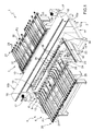
- numeral 1 indicates as a whole a machine for profiling elongated wood components 2 or the like for door and window frames, comprising an operating unit 3 for profiling the components 2; a feeding line 4 adapted to feed the components 2 in a substantially horizontal direction 5 and comprising, in turn, two feeding units 6, 7 arranged on opposite sides of unit 3 along direction 5; and a gripping and conveying unit 8, which is mounted at the operating unit 3, and is connected to units 6 and 7 at respective transferring stations 9, 10 for receiving the components 2 to be profiled from unit 6, holding the components 2 while profiling, and releasing the newly profiled components 2 onto unit 7.
- Operating unit 3 comprises a gantry frame 11 comprising, in turn, two vertical uprights 12 parallel to each other and a crosspiece 13, which is fixed at the free ends of the uprights 12, extends in a substantially horizontal direction 14 which is transversal to direction 5, and is laterally limited along the direction 5 itself by two flat faces 15a, 15b, on each of which a corresponding operating head 16 is mounted.
- Head 16 is coupled to the crosspiece 13 in a known manner, in order to make rectilinear movements in the direction 14, along the crosspiece 13 and under the bias of an actuating device of known type (not shown), and supports at least one electrospindle 17, which is mounted to the head 16 in a known manner for making rectilinear movements in a vertical direction 18 which is orthogonal to the directions 5 and 14, with respect to the head 16 and under the bias of an actuating device of known type (not shown), and is provided with a profiling tool 19 ( figure 4 ) of known type which is engaged on the electrospindle 17 itself.
- Feeding unit 6 is adapted to feed the components 2 in sequence from an inlet station 20 to the station 9, and comprises a plurality of belt conveyors 21 parallel to one another, which extend in the direction 5, and define a substantially horizontal resting plane P1 for the components 2.
- Unit 6 further comprises a plurality of supporting bars 22, each front of which protrudes from a corresponding conveyor 21 in direction 5, is limited at the top by a resting plane substantially coplanar to plane P1, and has a stopper element 23 protruding upwards from a free end of the corresponding bar 22, and cooperates with the stopper elements 23 of the other bars 22 to ensure a correct positioning of each component 2 in the direction 5.
- components 2 are transferred by the conveyors 21 onto the bars 22 and against the elements 23 by means of a pushing device 24 comprising a slide (not shown) movable in the direction 5 with respect to the conveyors 21, and a supporting bar 25 parallel to the direction 14 and coupled to the mentioned slide (not shown) in a known manner, in order to make rectilinear movements in the direction 18 with respect to the slide itself (not shown).
- a pushing device 24 comprising a slide (not shown) movable in the direction 5 with respect to the conveyors 21, and a supporting bar 25 parallel to the direction 14 and coupled to the mentioned slide (not shown) in a known manner, in order to make rectilinear movements in the direction 18 with respect to the slide itself (not shown).
- Bar 25 supports a plurality of elongated pushing elements 26, which are distributed along the bar 25 in the direction 14, which fronts protrude from the bar 25 in the direction 5, and are moved by the bar 25 itself in the direction 18 between a lowered position, in which the elements 26 are arranged underneath the plane P1, and a raised position in which the elements 26 protrude over the plane P1 to engage the back of each component 2 in the direction 5.
- feeding unit 7 is adapted to feed the components 2 in sequence from the station 10 to an outlet station 27, and comprises a plurality of belt conveyors 28 parallel to one another, which extend in the direction 5, and define a substantially horizontal resting plane P2 for the components 2 which is parallel to plane P1.
- unit 7 comprises a dragging device 29 comprising, in turn, a slide 30, which extends in the direction 14 and is coupled to the conveyor 28 in a known manner in order to make rectilinear movements in the direction 5 with respect to the conveyors 28 themselves, and a plurality of supporting and dragging bars 31 distributed along the slide 30 in the direction 14.
- a dragging device 29 comprising, in turn, a slide 30, which extends in the direction 14 and is coupled to the conveyor 28 in a known manner in order to make rectilinear movements in the direction 5 with respect to the conveyors 28 themselves, and a plurality of supporting and dragging bars 31 distributed along the slide 30 in the direction 14.
- the bars 31 have a substantially elongated L-shape, protrude from the back of slide 30 in the direction 5, are each provided with a respective end tooth 31a protruding upwards in the direction 18, are limited at the top by respective flat surfaces which are substantially coplanar to plane P2, and are moved by the slide 30 itself between an extracted position ( figure 4g ), in which the bars 31 protrude from the back of conveyors 28 in the direction 5, and a retracted position ( figure 4h ).
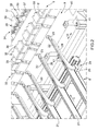
- the gripping and conveying unit 8 comprises two longitudinal guiding members 32, which extend in the direction 5, and are mounted to the frame 11 on opposite sides of the feeding line 4 in the direction 14, and two gripping and conveying devices 33, 34 facing each other and mounted in sequence on the longitudinal members 32 in the direction 5 itself.
- Each device 33, 34 comprises two runners 35, which are coupled to the longitudinal members 32 so as to slide and make rectilinear movements in the direction 5, along the longitudinal members 32 and under the bias of a known actuating device (not shown), and support a slide 36, which extends between the two runners 35 in the direction 14, and is coupled 35 so as to slide and make rectilinear movements in the direction 18, with respect to the runners 35 themselves and under the bias of a known actuating device (not shown).
- a plurality of lower jaws 37 are fixed onto the upper surface of the slide 36 (in this case twenty lower jaws 37) of corresponding clamping vices 38 further comprising respective upper jaws 39, which are equal in number to the number of jaws 37, are substantially L-shaped and are divided into a plurality of groups of jaws 39 (in this case two groups of jaws 39) independent from one another.
- each group of jaws 39 protrude upwards from a corresponding supporting slide 40 coupled to the slide 36 in a known manner to make rectilinear movements in the direction 18 between a position of clamping and a position of releasing at least one component 2, with respect to the slide 36 and under the bias of a plurality of actuating cylinders 41 (in this case three actuating cylinders 41) fixed to the slide 36 itself.
- the vices 38 of the device 33 are mounted in a staggered position with respect to supporting bars 22 and pushing elements 26 of unit 6 in the direction 14, while the vices 38 of the device 34 face the jaws 38 of the device 33 and are mounted in a staggered position with respect to the supporting bars 31 of unit 7 in the direction 14.
- Component 2 is thus fed by the pushing elements 26 of the pushing device 24 along the supporting bars 22 and against the stopper elements 23 to correctly place the component 2 in the direction 5 and to ensure that the component 2 itself is perfectly parallel to the direction 14 ( figure 4b ).
- the clamping vices 38 of the gripping and conveying device 33 are moved to a raised position, in which the corresponding lower jaws 37 are arranged substantially coplanar to plane P1 and the corresponding upper jaws 39 protrude over the plane P1; the device 33 is fed in the direction 5; and the jaws 39 themselves are moved to the their position of clamping the component 2 ( figure 4c ).
- the component 2 is raised from plane P1 and fed downstream of the stopper elements 23 to allow the operating head 16 mounted to the face 15a to longitudinally profile the face 2b protruding out from the vices 38 themselves in the direction 14 ( figure 4d ).
- the component 2 is transferred from the vices 38 of the device 33 to the vices 38 of the device 34 ( figure 4e ), and the operating head 16 mounted to the face 15b is moved in the direction 14 for longitudinally profiling the face 2a protruding out from the vices 38 themselves ( figure 4f ).
- the supporting bars 31 of the dragging device 29 are moved to the extracted position thereof, and the component 2 is firstly moved over the teeth 31a and then released onto the bars 31 themselves by combining the movement of the device 34 in the direction 5 with the movement of the corresponding vices 38 in the direction 18 ( figure 4g ).
- the supporting bars 22 are movable between a lowered position, in which the corresponding stopper elements 23 are arranged underneath the plane P1, and a raised position in which the corresponding elements 23 protrude over the plane P1 itself.
- the supporting bars 31 are movable between a lowered position, in which the corresponding teeth 31a are arranged underneath the plane P2, and a raised position in which the corresponding teeth 31a protrude over the plane P2 itself.
Landscapes
- Engineering & Computer Science (AREA)
- Life Sciences & Earth Sciences (AREA)
- Mechanical Engineering (AREA)
- Wood Science & Technology (AREA)
- Forests & Forestry (AREA)
- Automatic Assembly (AREA)
- Dovetailed Work, And Nailing Machines And Stapling Machines For Wood (AREA)
- Turbine Rotor Nozzle Sealing (AREA)
Applications Claiming Priority (1)
| Application Number | Priority Date | Filing Date | Title |
|---|---|---|---|
| ITBO20080186 ITBO20080186A1 (it) | 2008-03-25 | 2008-03-25 | Metodo e macchina per la profilatura di componenti di legno o simili di forma allungata, in particolare componenti per infissi |
Publications (3)
| Publication Number | Publication Date |
|---|---|
| EP2105269A2 true EP2105269A2 (de) | 2009-09-30 |
| EP2105269A3 EP2105269A3 (de) | 2012-04-11 |
| EP2105269B1 EP2105269B1 (de) | 2014-02-12 |
Family
ID=40292671
Family Applications (1)
| Application Number | Title | Priority Date | Filing Date |
|---|---|---|---|
| EP20090155985 Active EP2105269B1 (de) | 2008-03-25 | 2009-03-24 | Verfahren und Maschine zur Profilierung verlängerter Holzkomponenten oder ähnlicher Elemente, insbesondere für Tür- und Fensterrahmen |
Country Status (2)
| Country | Link |
|---|---|
| EP (1) | EP2105269B1 (de) |
| IT (1) | ITBO20080186A1 (de) |
Cited By (5)
| Publication number | Priority date | Publication date | Assignee | Title |
|---|---|---|---|---|
| ITMO20100051A1 (it) * | 2010-03-02 | 2011-09-03 | Scm Group Spa | Apparato per la lavorazione di pezzi |
| ITPD20100317A1 (it) * | 2010-10-21 | 2012-04-22 | Working Process S R L | Centro di lavoro con piano di riscontro e raddrizzamento separato |
| WO2017055111A1 (de) * | 2015-09-29 | 2017-04-06 | Homag Gmbh | Bearbeitungsvorrichtung |
| IT201600093296A1 (it) * | 2016-09-16 | 2018-03-16 | Cms Spa | Centro di lavoro a controllo numerico |
| IT202000024955A1 (it) * | 2020-10-22 | 2022-04-22 | Lorenzo Lattanzi | Metodo e macchina per la realizzazione di componenti di legno o simili |
Family Cites Families (2)
| Publication number | Priority date | Publication date | Assignee | Title |
|---|---|---|---|---|
| IT1187376B (it) * | 1985-05-15 | 1987-12-23 | S C M Spa | Macchina tenonatrice |
| ITMO20060021A1 (it) * | 2006-01-20 | 2007-07-21 | Scm Group Spa | Macchina utensile |
-
2008
- 2008-03-25 IT ITBO20080186 patent/ITBO20080186A1/it unknown
-
2009
- 2009-03-24 EP EP20090155985 patent/EP2105269B1/de active Active
Cited By (10)
| Publication number | Priority date | Publication date | Assignee | Title |
|---|---|---|---|---|
| ITMO20100051A1 (it) * | 2010-03-02 | 2011-09-03 | Scm Group Spa | Apparato per la lavorazione di pezzi |
| EP2363260A1 (de) * | 2010-03-02 | 2011-09-07 | SCM Group S.p.A. | Einrichtung zum Bearbeiten von Werkstücken |
| ITPD20100317A1 (it) * | 2010-10-21 | 2012-04-22 | Working Process S R L | Centro di lavoro con piano di riscontro e raddrizzamento separato |
| WO2017055111A1 (de) * | 2015-09-29 | 2017-04-06 | Homag Gmbh | Bearbeitungsvorrichtung |
| CN108025451A (zh) * | 2015-09-29 | 2018-05-11 | 豪迈公司 | 加工设备 |
| US20180272557A1 (en) * | 2015-09-29 | 2018-09-27 | Homag Gmbh | Machining device |
| US10940607B2 (en) | 2015-09-29 | 2021-03-09 | Homag Gmbh | Machining device |
| IT201600093296A1 (it) * | 2016-09-16 | 2018-03-16 | Cms Spa | Centro di lavoro a controllo numerico |
| IT202000024955A1 (it) * | 2020-10-22 | 2022-04-22 | Lorenzo Lattanzi | Metodo e macchina per la realizzazione di componenti di legno o simili |
| EP3988267A1 (de) * | 2020-10-22 | 2022-04-27 | SCM Group S.p.A. | Verfahren und maschine zur herstellung von bauteilen aus holz oder dergleichen |
Also Published As
| Publication number | Publication date |
|---|---|
| EP2105269B1 (de) | 2014-02-12 |
| EP2105269A3 (de) | 2012-04-11 |
| ITBO20080186A1 (it) | 2009-09-26 |
Similar Documents
| Publication | Publication Date | Title |
|---|---|---|
| US10668643B2 (en) | Machining device | |
| EP2241425B1 (de) | Bearbeitungsverfahren von einem Bauteil aus Holz oder dergleichen, insbesondere für Bestandteile von Tür- oder Fensterrahmen | |
| EP2105269B1 (de) | Verfahren und Maschine zur Profilierung verlängerter Holzkomponenten oder ähnlicher Elemente, insbesondere für Tür- und Fensterrahmen | |
| EP1810802A1 (de) | Werkzeugmaschine | |
| CA2645172A1 (en) | Stamping apparatus with feed device | |
| KR102358140B1 (ko) | 철망 절곡장치 | |
| CN105015815B (zh) | 一种电池盒包膜机 | |
| EP1832402B1 (de) | Formmaschine zum Bearbeiten von länglichen Werkstücken aus Holz oder dergleichen in Längsrichtung, insbesondere für Bestandteile von Tür- oder Fensterrahmen | |
| EP2159023A2 (de) | Bearbeitungszentrum zur Verarbeitung von Komponenten aus Holz oder dergleichen mit einer länglichen Form, insbesondere Komponenten für Rahmen | |
| EP2098344B1 (de) | Verfahren und Vorrichtung zur maschinellen Verarbeitung von Holzkomponenten oder Ähnlichem | |
| CN105438571B (zh) | 一种剥料机构 | |
| EP2508314A1 (de) | Vorrichtung und Verfahren zur Bearbeitung von Platten | |
| CN111889913A (zh) | 一种桁架端面自动焊接设备 | |
| EP3167969B1 (de) | Maschine zur herstellen von stangen aus aluminium, leichtlegierungen, pvc oder dergleichen | |
| EP2159022A2 (de) | Hobelmaschine zum Hobeln von Bauteilen aus Holz oder ähnliches. | |
| CN219859093U (zh) | 一种送料设备 | |
| EP1475204B1 (de) | Werkzeugmaschine zur Bearbeitung von Holzplatten oder dergleichen | |
| EP2210723A1 (de) | Machine und Verfahren für die Bearbeitung von Holz oder ähnlichen Materialien | |
| EP2667985B1 (de) | Vorrichtung zur herstellung eines verstärkungsnetzes | |
| EP3069838B1 (de) | Maschine zur verarbeitung von paneelen aus holz und dergleichen | |
| CN204668407U (zh) | 一种电池盒包膜平台 | |
| CN210908363U (zh) | 长条形型材自动喂料切割装置 | |
| KR20150009279A (ko) | 몰딩 공급장치 | |
| CN209094908U (zh) | 一种矩形边框自动组框机 | |
| CN221396473U (zh) | 一种片材拾取堆叠装置 |
Legal Events
| Date | Code | Title | Description |
|---|---|---|---|
| PUAI | Public reference made under article 153(3) epc to a published international application that has entered the european phase |
Free format text: ORIGINAL CODE: 0009012 |
|
| AK | Designated contracting states |
Kind code of ref document: A2 Designated state(s): AT BE BG CH CY CZ DE DK EE ES FI FR GB GR HR HU IE IS IT LI LT LU LV MC MK MT NL NO PL PT RO SE SI SK TR |
|
| AX | Request for extension of the european patent |
Extension state: AL BA RS |
|
| PUAL | Search report despatched |
Free format text: ORIGINAL CODE: 0009013 |
|
| AK | Designated contracting states |
Kind code of ref document: A3 Designated state(s): AT BE BG CH CY CZ DE DK EE ES FI FR GB GR HR HU IE IS IT LI LT LU LV MC MK MT NL NO PL PT RO SE SI SK TR |
|
| AX | Request for extension of the european patent |
Extension state: AL BA RS |
|
| RIC1 | Information provided on ipc code assigned before grant |
Ipc: B27F 1/08 20060101ALI20120308BHEP Ipc: B27M 1/08 20060101ALI20120308BHEP Ipc: B27F 1/02 20060101AFI20120308BHEP |
|
| 17P | Request for examination filed |
Effective date: 20121011 |
|
| AKX | Designation fees paid |
Designated state(s): AT BE BG CH CY CZ DE DK EE ES FI FR GB GR HR HU IE IS IT LI LT LU LV MC MK MT NL NO PL PT RO SE SI SK TR |
|
| GRAP | Despatch of communication of intention to grant a patent |
Free format text: ORIGINAL CODE: EPIDOSNIGR1 |
|
| INTG | Intention to grant announced |
Effective date: 20130828 |
|
| GRAS | Grant fee paid |
Free format text: ORIGINAL CODE: EPIDOSNIGR3 |
|
| GRAA | (expected) grant |
Free format text: ORIGINAL CODE: 0009210 |
|
| AK | Designated contracting states |
Kind code of ref document: B1 Designated state(s): AT BE BG CH CY CZ DE DK EE ES FI FR GB GR HR HU IE IS IT LI LT LU LV MC MK MT NL NO PL PT RO SE SI SK TR |
|
| REG | Reference to a national code |
Ref country code: GB Ref legal event code: FG4D |
|
| REG | Reference to a national code |
Ref country code: CH Ref legal event code: EP |
|
| REG | Reference to a national code |
Ref country code: AT Ref legal event code: REF Ref document number: 651928 Country of ref document: AT Kind code of ref document: T Effective date: 20140215 |
|
| REG | Reference to a national code |
Ref country code: IE Ref legal event code: FG4D |
|
| REG | Reference to a national code |
Ref country code: DE Ref legal event code: R096 Ref document number: 602009021761 Country of ref document: DE Effective date: 20140327 |
|
| REG | Reference to a national code |
Ref country code: NL Ref legal event code: VDEP Effective date: 20140212 |
|
| REG | Reference to a national code |
Ref country code: AT Ref legal event code: MK05 Ref document number: 651928 Country of ref document: AT Kind code of ref document: T Effective date: 20140212 |
|
| REG | Reference to a national code |
Ref country code: LT Ref legal event code: MG4D |
|
| PG25 | Lapsed in a contracting state [announced via postgrant information from national office to epo] |
Ref country code: IS Free format text: LAPSE BECAUSE OF FAILURE TO SUBMIT A TRANSLATION OF THE DESCRIPTION OR TO PAY THE FEE WITHIN THE PRESCRIBED TIME-LIMIT Effective date: 20140612 Ref country code: NO Free format text: LAPSE BECAUSE OF FAILURE TO SUBMIT A TRANSLATION OF THE DESCRIPTION OR TO PAY THE FEE WITHIN THE PRESCRIBED TIME-LIMIT Effective date: 20140512 Ref country code: LT Free format text: LAPSE BECAUSE OF FAILURE TO SUBMIT A TRANSLATION OF THE DESCRIPTION OR TO PAY THE FEE WITHIN THE PRESCRIBED TIME-LIMIT Effective date: 20140212 |
|
| PG25 | Lapsed in a contracting state [announced via postgrant information from national office to epo] |
Ref country code: AT Free format text: LAPSE BECAUSE OF FAILURE TO SUBMIT A TRANSLATION OF THE DESCRIPTION OR TO PAY THE FEE WITHIN THE PRESCRIBED TIME-LIMIT Effective date: 20140212 Ref country code: NL Free format text: LAPSE BECAUSE OF FAILURE TO SUBMIT A TRANSLATION OF THE DESCRIPTION OR TO PAY THE FEE WITHIN THE PRESCRIBED TIME-LIMIT Effective date: 20140212 Ref country code: CY Free format text: LAPSE BECAUSE OF FAILURE TO SUBMIT A TRANSLATION OF THE DESCRIPTION OR TO PAY THE FEE WITHIN THE PRESCRIBED TIME-LIMIT Effective date: 20140212 Ref country code: ES Free format text: LAPSE BECAUSE OF FAILURE TO SUBMIT A TRANSLATION OF THE DESCRIPTION OR TO PAY THE FEE WITHIN THE PRESCRIBED TIME-LIMIT Effective date: 20140212 Ref country code: FI Free format text: LAPSE BECAUSE OF FAILURE TO SUBMIT A TRANSLATION OF THE DESCRIPTION OR TO PAY THE FEE WITHIN THE PRESCRIBED TIME-LIMIT Effective date: 20140212 Ref country code: PT Free format text: LAPSE BECAUSE OF FAILURE TO SUBMIT A TRANSLATION OF THE DESCRIPTION OR TO PAY THE FEE WITHIN THE PRESCRIBED TIME-LIMIT Effective date: 20140612 Ref country code: SE Free format text: LAPSE BECAUSE OF FAILURE TO SUBMIT A TRANSLATION OF THE DESCRIPTION OR TO PAY THE FEE WITHIN THE PRESCRIBED TIME-LIMIT Effective date: 20140212 |
|
| PG25 | Lapsed in a contracting state [announced via postgrant information from national office to epo] |
Ref country code: LV Free format text: LAPSE BECAUSE OF FAILURE TO SUBMIT A TRANSLATION OF THE DESCRIPTION OR TO PAY THE FEE WITHIN THE PRESCRIBED TIME-LIMIT Effective date: 20140212 Ref country code: BE Free format text: LAPSE BECAUSE OF FAILURE TO SUBMIT A TRANSLATION OF THE DESCRIPTION OR TO PAY THE FEE WITHIN THE PRESCRIBED TIME-LIMIT Effective date: 20140212 Ref country code: HR Free format text: LAPSE BECAUSE OF FAILURE TO SUBMIT A TRANSLATION OF THE DESCRIPTION OR TO PAY THE FEE WITHIN THE PRESCRIBED TIME-LIMIT Effective date: 20140212 |
|
| PG25 | Lapsed in a contracting state [announced via postgrant information from national office to epo] |
Ref country code: EE Free format text: LAPSE BECAUSE OF FAILURE TO SUBMIT A TRANSLATION OF THE DESCRIPTION OR TO PAY THE FEE WITHIN THE PRESCRIBED TIME-LIMIT Effective date: 20140212 Ref country code: DK Free format text: LAPSE BECAUSE OF FAILURE TO SUBMIT A TRANSLATION OF THE DESCRIPTION OR TO PAY THE FEE WITHIN THE PRESCRIBED TIME-LIMIT Effective date: 20140212 Ref country code: CZ Free format text: LAPSE BECAUSE OF FAILURE TO SUBMIT A TRANSLATION OF THE DESCRIPTION OR TO PAY THE FEE WITHIN THE PRESCRIBED TIME-LIMIT Effective date: 20140212 Ref country code: RO Free format text: LAPSE BECAUSE OF FAILURE TO SUBMIT A TRANSLATION OF THE DESCRIPTION OR TO PAY THE FEE WITHIN THE PRESCRIBED TIME-LIMIT Effective date: 20140212 |
|
| REG | Reference to a national code |
Ref country code: CH Ref legal event code: PL |
|
| REG | Reference to a national code |
Ref country code: DE Ref legal event code: R097 Ref document number: 602009021761 Country of ref document: DE |
|
| PG25 | Lapsed in a contracting state [announced via postgrant information from national office to epo] |
Ref country code: PL Free format text: LAPSE BECAUSE OF FAILURE TO SUBMIT A TRANSLATION OF THE DESCRIPTION OR TO PAY THE FEE WITHIN THE PRESCRIBED TIME-LIMIT Effective date: 20140212 Ref country code: MC Free format text: LAPSE BECAUSE OF FAILURE TO SUBMIT A TRANSLATION OF THE DESCRIPTION OR TO PAY THE FEE WITHIN THE PRESCRIBED TIME-LIMIT Effective date: 20140212 Ref country code: SK Free format text: LAPSE BECAUSE OF FAILURE TO SUBMIT A TRANSLATION OF THE DESCRIPTION OR TO PAY THE FEE WITHIN THE PRESCRIBED TIME-LIMIT Effective date: 20140212 |
|
| PLBE | No opposition filed within time limit |
Free format text: ORIGINAL CODE: 0009261 |
|
| STAA | Information on the status of an ep patent application or granted ep patent |
Free format text: STATUS: NO OPPOSITION FILED WITHIN TIME LIMIT |
|
| REG | Reference to a national code |
Ref country code: FR Ref legal event code: ST Effective date: 20141128 |
|
| REG | Reference to a national code |
Ref country code: IE Ref legal event code: MM4A |
|
| 26N | No opposition filed |
Effective date: 20141113 |
|
| GBPC | Gb: european patent ceased through non-payment of renewal fee |
Effective date: 20140512 |
|
| PG25 | Lapsed in a contracting state [announced via postgrant information from national office to epo] |
Ref country code: CH Free format text: LAPSE BECAUSE OF NON-PAYMENT OF DUE FEES Effective date: 20140331 Ref country code: IE Free format text: LAPSE BECAUSE OF NON-PAYMENT OF DUE FEES Effective date: 20140324 Ref country code: LI Free format text: LAPSE BECAUSE OF NON-PAYMENT OF DUE FEES Effective date: 20140331 Ref country code: FR Free format text: LAPSE BECAUSE OF NON-PAYMENT OF DUE FEES Effective date: 20140414 |
|
| REG | Reference to a national code |
Ref country code: DE Ref legal event code: R097 Ref document number: 602009021761 Country of ref document: DE Effective date: 20141113 |
|
| PG25 | Lapsed in a contracting state [announced via postgrant information from national office to epo] |
Ref country code: GB Free format text: LAPSE BECAUSE OF NON-PAYMENT OF DUE FEES Effective date: 20140512 Ref country code: SI Free format text: LAPSE BECAUSE OF FAILURE TO SUBMIT A TRANSLATION OF THE DESCRIPTION OR TO PAY THE FEE WITHIN THE PRESCRIBED TIME-LIMIT Effective date: 20140212 |
|
| PG25 | Lapsed in a contracting state [announced via postgrant information from national office to epo] |
Ref country code: MT Free format text: LAPSE BECAUSE OF FAILURE TO SUBMIT A TRANSLATION OF THE DESCRIPTION OR TO PAY THE FEE WITHIN THE PRESCRIBED TIME-LIMIT Effective date: 20140212 |
|
| PG25 | Lapsed in a contracting state [announced via postgrant information from national office to epo] |
Ref country code: GR Free format text: LAPSE BECAUSE OF FAILURE TO SUBMIT A TRANSLATION OF THE DESCRIPTION OR TO PAY THE FEE WITHIN THE PRESCRIBED TIME-LIMIT Effective date: 20140513 Ref country code: BG Free format text: LAPSE BECAUSE OF FAILURE TO SUBMIT A TRANSLATION OF THE DESCRIPTION OR TO PAY THE FEE WITHIN THE PRESCRIBED TIME-LIMIT Effective date: 20140212 |
|
| PG25 | Lapsed in a contracting state [announced via postgrant information from national office to epo] |
Ref country code: TR Free format text: LAPSE BECAUSE OF FAILURE TO SUBMIT A TRANSLATION OF THE DESCRIPTION OR TO PAY THE FEE WITHIN THE PRESCRIBED TIME-LIMIT Effective date: 20140212 Ref country code: HU Free format text: LAPSE BECAUSE OF FAILURE TO SUBMIT A TRANSLATION OF THE DESCRIPTION OR TO PAY THE FEE WITHIN THE PRESCRIBED TIME-LIMIT; INVALID AB INITIO Effective date: 20090324 Ref country code: LU Free format text: LAPSE BECAUSE OF NON-PAYMENT OF DUE FEES Effective date: 20140324 |
|
| PG25 | Lapsed in a contracting state [announced via postgrant information from national office to epo] |
Ref country code: MK Free format text: LAPSE BECAUSE OF FAILURE TO SUBMIT A TRANSLATION OF THE DESCRIPTION OR TO PAY THE FEE WITHIN THE PRESCRIBED TIME-LIMIT Effective date: 20140212 |
|
| PGFP | Annual fee paid to national office [announced via postgrant information from national office to epo] |
Ref country code: DE Payment date: 20260320 Year of fee payment: 18 |
|
| PGFP | Annual fee paid to national office [announced via postgrant information from national office to epo] |
Ref country code: IT Payment date: 20260302 Year of fee payment: 18 |