EP2105278B1 - Installation de thermoformage destinée à la fabrication de corps en feuille de matière plastique, et son procédé de fabrication - Google Patents
Installation de thermoformage destinée à la fabrication de corps en feuille de matière plastique, et son procédé de fabrication Download PDFInfo
- Publication number
- EP2105278B1 EP2105278B1 EP09006715A EP09006715A EP2105278B1 EP 2105278 B1 EP2105278 B1 EP 2105278B1 EP 09006715 A EP09006715 A EP 09006715A EP 09006715 A EP09006715 A EP 09006715A EP 2105278 B1 EP2105278 B1 EP 2105278B1
- Authority
- EP
- European Patent Office
- Prior art keywords
- tool table
- upper tool
- drive
- drive means
- intermediary
- Prior art date
- Legal status (The legal status is an assumption and is not a legal conclusion. Google has not performed a legal analysis and makes no representation as to the accuracy of the status listed.)
- Expired - Lifetime
Links
Images




Classifications
-
- B—PERFORMING OPERATIONS; TRANSPORTING
- B29—WORKING OF PLASTICS; WORKING OF SUBSTANCES IN A PLASTIC STATE IN GENERAL
- B29C—SHAPING OR JOINING OF PLASTICS; SHAPING OF MATERIAL IN A PLASTIC STATE, NOT OTHERWISE PROVIDED FOR; AFTER-TREATMENT OF THE SHAPED PRODUCTS, e.g. REPAIRING
- B29C51/00—Shaping by thermoforming, i.e. shaping sheets or sheet like preforms after heating, e.g. shaping sheets in matched moulds or by deep-drawing; Apparatus therefor
- B29C51/04—Combined thermoforming and prestretching, e.g. biaxial stretching
-
- B—PERFORMING OPERATIONS; TRANSPORTING
- B29—WORKING OF PLASTICS; WORKING OF SUBSTANCES IN A PLASTIC STATE IN GENERAL
- B29C—SHAPING OR JOINING OF PLASTICS; SHAPING OF MATERIAL IN A PLASTIC STATE, NOT OTHERWISE PROVIDED FOR; AFTER-TREATMENT OF THE SHAPED PRODUCTS, e.g. REPAIRING
- B29C51/00—Shaping by thermoforming, i.e. shaping sheets or sheet like preforms after heating, e.g. shaping sheets in matched moulds or by deep-drawing; Apparatus therefor
- B29C51/18—Thermoforming apparatus
- B29C51/20—Thermoforming apparatus having movable moulds or mould parts
- B29C51/22—Thermoforming apparatus having movable moulds or mould parts rotatable about an axis
-
- B—PERFORMING OPERATIONS; TRANSPORTING
- B29—WORKING OF PLASTICS; WORKING OF SUBSTANCES IN A PLASTIC STATE IN GENERAL
- B29C—SHAPING OR JOINING OF PLASTICS; SHAPING OF MATERIAL IN A PLASTIC STATE, NOT OTHERWISE PROVIDED FOR; AFTER-TREATMENT OF THE SHAPED PRODUCTS, e.g. REPAIRING
- B29C51/00—Shaping by thermoforming, i.e. shaping sheets or sheet like preforms after heating, e.g. shaping sheets in matched moulds or by deep-drawing; Apparatus therefor
- B29C51/26—Component parts, details or accessories; Auxiliary operations
-
- B—PERFORMING OPERATIONS; TRANSPORTING
- B29—WORKING OF PLASTICS; WORKING OF SUBSTANCES IN A PLASTIC STATE IN GENERAL
- B29C—SHAPING OR JOINING OF PLASTICS; SHAPING OF MATERIAL IN A PLASTIC STATE, NOT OTHERWISE PROVIDED FOR; AFTER-TREATMENT OF THE SHAPED PRODUCTS, e.g. REPAIRING
- B29C51/00—Shaping by thermoforming, i.e. shaping sheets or sheet like preforms after heating, e.g. shaping sheets in matched moulds or by deep-drawing; Apparatus therefor
- B29C51/26—Component parts, details or accessories; Auxiliary operations
- B29C51/30—Moulds
- B29C51/38—Opening, closing or clamping means
-
- B—PERFORMING OPERATIONS; TRANSPORTING
- B29—WORKING OF PLASTICS; WORKING OF SUBSTANCES IN A PLASTIC STATE IN GENERAL
- B29C—SHAPING OR JOINING OF PLASTICS; SHAPING OF MATERIAL IN A PLASTIC STATE, NOT OTHERWISE PROVIDED FOR; AFTER-TREATMENT OF THE SHAPED PRODUCTS, e.g. REPAIRING
- B29C51/00—Shaping by thermoforming, i.e. shaping sheets or sheet like preforms after heating, e.g. shaping sheets in matched moulds or by deep-drawing; Apparatus therefor
- B29C51/26—Component parts, details or accessories; Auxiliary operations
- B29C51/46—Measuring, controlling or regulating
-
- B—PERFORMING OPERATIONS; TRANSPORTING
- B29—WORKING OF PLASTICS; WORKING OF SUBSTANCES IN A PLASTIC STATE IN GENERAL
- B29C—SHAPING OR JOINING OF PLASTICS; SHAPING OF MATERIAL IN A PLASTIC STATE, NOT OTHERWISE PROVIDED FOR; AFTER-TREATMENT OF THE SHAPED PRODUCTS, e.g. REPAIRING
- B29C2791/00—Shaping characteristics in general
- B29C2791/002—Making articles of definite length, i.e. discrete articles
-
- B—PERFORMING OPERATIONS; TRANSPORTING
- B29—WORKING OF PLASTICS; WORKING OF SUBSTANCES IN A PLASTIC STATE IN GENERAL
- B29C—SHAPING OR JOINING OF PLASTICS; SHAPING OF MATERIAL IN A PLASTIC STATE, NOT OTHERWISE PROVIDED FOR; AFTER-TREATMENT OF THE SHAPED PRODUCTS, e.g. REPAIRING
- B29C2791/00—Shaping characteristics in general
- B29C2791/004—Shaping under special conditions
- B29C2791/006—Using vacuum
-
- B—PERFORMING OPERATIONS; TRANSPORTING
- B29—WORKING OF PLASTICS; WORKING OF SUBSTANCES IN A PLASTIC STATE IN GENERAL
- B29C—SHAPING OR JOINING OF PLASTICS; SHAPING OF MATERIAL IN A PLASTIC STATE, NOT OTHERWISE PROVIDED FOR; AFTER-TREATMENT OF THE SHAPED PRODUCTS, e.g. REPAIRING
- B29C2791/00—Shaping characteristics in general
- B29C2791/004—Shaping under special conditions
- B29C2791/007—Using fluid under pressure
-
- B—PERFORMING OPERATIONS; TRANSPORTING
- B29—WORKING OF PLASTICS; WORKING OF SUBSTANCES IN A PLASTIC STATE IN GENERAL
- B29C—SHAPING OR JOINING OF PLASTICS; SHAPING OF MATERIAL IN A PLASTIC STATE, NOT OTHERWISE PROVIDED FOR; AFTER-TREATMENT OF THE SHAPED PRODUCTS, e.g. REPAIRING
- B29C2793/00—Shaping techniques involving a cutting or machining operation
- B29C2793/009—Shaping techniques involving a cutting or machining operation after shaping
-
- B—PERFORMING OPERATIONS; TRANSPORTING
- B29—WORKING OF PLASTICS; WORKING OF SUBSTANCES IN A PLASTIC STATE IN GENERAL
- B29C—SHAPING OR JOINING OF PLASTICS; SHAPING OF MATERIAL IN A PLASTIC STATE, NOT OTHERWISE PROVIDED FOR; AFTER-TREATMENT OF THE SHAPED PRODUCTS, e.g. REPAIRING
- B29C35/00—Heating, cooling or curing, e.g. crosslinking or vulcanising; Apparatus therefor
- B29C35/16—Cooling
-
- B—PERFORMING OPERATIONS; TRANSPORTING
- B29—WORKING OF PLASTICS; WORKING OF SUBSTANCES IN A PLASTIC STATE IN GENERAL
- B29C—SHAPING OR JOINING OF PLASTICS; SHAPING OF MATERIAL IN A PLASTIC STATE, NOT OTHERWISE PROVIDED FOR; AFTER-TREATMENT OF THE SHAPED PRODUCTS, e.g. REPAIRING
- B29C51/00—Shaping by thermoforming, i.e. shaping sheets or sheet like preforms after heating, e.g. shaping sheets in matched moulds or by deep-drawing; Apparatus therefor
- B29C51/26—Component parts, details or accessories; Auxiliary operations
- B29C51/42—Heating or cooling
- B29C51/428—Heating or cooling of moulds or mould parts
-
- B—PERFORMING OPERATIONS; TRANSPORTING
- B29—WORKING OF PLASTICS; WORKING OF SUBSTANCES IN A PLASTIC STATE IN GENERAL
- B29C—SHAPING OR JOINING OF PLASTICS; SHAPING OF MATERIAL IN A PLASTIC STATE, NOT OTHERWISE PROVIDED FOR; AFTER-TREATMENT OF THE SHAPED PRODUCTS, e.g. REPAIRING
- B29C51/00—Shaping by thermoforming, i.e. shaping sheets or sheet like preforms after heating, e.g. shaping sheets in matched moulds or by deep-drawing; Apparatus therefor
- B29C51/26—Component parts, details or accessories; Auxiliary operations
- B29C51/44—Removing or ejecting moulded articles
-
- B—PERFORMING OPERATIONS; TRANSPORTING
- B29—WORKING OF PLASTICS; WORKING OF SUBSTANCES IN A PLASTIC STATE IN GENERAL
- B29C—SHAPING OR JOINING OF PLASTICS; SHAPING OF MATERIAL IN A PLASTIC STATE, NOT OTHERWISE PROVIDED FOR; AFTER-TREATMENT OF THE SHAPED PRODUCTS, e.g. REPAIRING
- B29C51/00—Shaping by thermoforming, i.e. shaping sheets or sheet like preforms after heating, e.g. shaping sheets in matched moulds or by deep-drawing; Apparatus therefor
- B29C51/26—Component parts, details or accessories; Auxiliary operations
- B29C51/44—Removing or ejecting moulded articles
- B29C51/445—Removing or ejecting moulded articles from a support after moulding, e.g. by cutting
-
- B—PERFORMING OPERATIONS; TRANSPORTING
- B29—WORKING OF PLASTICS; WORKING OF SUBSTANCES IN A PLASTIC STATE IN GENERAL
- B29K—INDEXING SCHEME ASSOCIATED WITH SUBCLASSES B29B, B29C OR B29D, RELATING TO MOULDING MATERIALS OR TO MATERIALS FOR MOULDS, REINFORCEMENTS, FILLERS OR PREFORMED PARTS, e.g. INSERTS
- B29K2023/00—Use of polyalkenes or derivatives thereof as moulding material
- B29K2023/10—Polymers of propylene
- B29K2023/12—PP, i.e. polypropylene
-
- B—PERFORMING OPERATIONS; TRANSPORTING
- B29—WORKING OF PLASTICS; WORKING OF SUBSTANCES IN A PLASTIC STATE IN GENERAL
- B29K—INDEXING SCHEME ASSOCIATED WITH SUBCLASSES B29B, B29C OR B29D, RELATING TO MOULDING MATERIALS OR TO MATERIALS FOR MOULDS, REINFORCEMENTS, FILLERS OR PREFORMED PARTS, e.g. INSERTS
- B29K2025/00—Use of polymers of vinyl-aromatic compounds or derivatives thereof as moulding material
-
- B—PERFORMING OPERATIONS; TRANSPORTING
- B29—WORKING OF PLASTICS; WORKING OF SUBSTANCES IN A PLASTIC STATE IN GENERAL
- B29K—INDEXING SCHEME ASSOCIATED WITH SUBCLASSES B29B, B29C OR B29D, RELATING TO MOULDING MATERIALS OR TO MATERIALS FOR MOULDS, REINFORCEMENTS, FILLERS OR PREFORMED PARTS, e.g. INSERTS
- B29K2027/00—Use of polyvinylhalogenides or derivatives thereof as moulding material
- B29K2027/06—PVC, i.e. polyvinylchloride
-
- B—PERFORMING OPERATIONS; TRANSPORTING
- B29—WORKING OF PLASTICS; WORKING OF SUBSTANCES IN A PLASTIC STATE IN GENERAL
- B29K—INDEXING SCHEME ASSOCIATED WITH SUBCLASSES B29B, B29C OR B29D, RELATING TO MOULDING MATERIALS OR TO MATERIALS FOR MOULDS, REINFORCEMENTS, FILLERS OR PREFORMED PARTS, e.g. INSERTS
- B29K2055/00—Use of specific polymers obtained by polymerisation reactions only involving carbon-to-carbon unsaturated bonds, not provided for in a single one of main groups B29K2023/00 - B29K2049/00, e.g. having a vinyl group, as moulding material
- B29K2055/02—ABS polymers, i.e. acrylonitrile-butadiene-styrene polymers
-
- B—PERFORMING OPERATIONS; TRANSPORTING
- B29—WORKING OF PLASTICS; WORKING OF SUBSTANCES IN A PLASTIC STATE IN GENERAL
- B29K—INDEXING SCHEME ASSOCIATED WITH SUBCLASSES B29B, B29C OR B29D, RELATING TO MOULDING MATERIALS OR TO MATERIALS FOR MOULDS, REINFORCEMENTS, FILLERS OR PREFORMED PARTS, e.g. INSERTS
- B29K2067/00—Use of polyesters or derivatives thereof, as moulding material
-
- B—PERFORMING OPERATIONS; TRANSPORTING
- B29—WORKING OF PLASTICS; WORKING OF SUBSTANCES IN A PLASTIC STATE IN GENERAL
- B29L—INDEXING SCHEME ASSOCIATED WITH SUBCLASS B29C, RELATING TO PARTICULAR ARTICLES
- B29L2031/00—Other particular articles
- B29L2031/56—Stoppers or lids for bottles, jars, or the like, e.g. closures
- B29L2031/565—Stoppers or lids for bottles, jars, or the like, e.g. closures for containers
-
- B—PERFORMING OPERATIONS; TRANSPORTING
- B29—WORKING OF PLASTICS; WORKING OF SUBSTANCES IN A PLASTIC STATE IN GENERAL
- B29L—INDEXING SCHEME ASSOCIATED WITH SUBCLASS B29C, RELATING TO PARTICULAR ARTICLES
- B29L2031/00—Other particular articles
- B29L2031/712—Containers; Packaging elements or accessories, Packages
- B29L2031/7132—Bowls, Cups, Glasses
-
- B—PERFORMING OPERATIONS; TRANSPORTING
- B29—WORKING OF PLASTICS; WORKING OF SUBSTANCES IN A PLASTIC STATE IN GENERAL
- B29L—INDEXING SCHEME ASSOCIATED WITH SUBCLASS B29C, RELATING TO PARTICULAR ARTICLES
- B29L2031/00—Other particular articles
- B29L2031/712—Containers; Packaging elements or accessories, Packages
- B29L2031/7162—Boxes, cartons, cases
Definitions
- the present invention relates to a thermoforming plant for the production of moldings of plastic film, such as cups, containers, lids, food packaging or the like., With a two-part mold having forming station, according to the preamble of claim 1, and a method for producing such moldings according to the preamble of claim 8.
- Thermoforming plants have become known in various variants and embodiments in practice.
- a two-part mold is used to produce container-shaped article or molded body made of thermoplastic material.
- a mold half, the so-called upper tool is attached to the upper tool table and connected to this adjustable adjustable fest aus usually connected to the frame or frame of the thermoforming system, so that the upper tool can be adjusted to the moldings to be produced in each case.
- the other mold half, the so-called lower tool is movably guided in the frame or frame of the thermoforming system.
- the mold halves To mold the moldings are the mold halves, so the upper and the lower tool, in a mutually facing closed position. Between the upper and the lower tool, a frequently preheated and thus readily plastically deformable plastic film is arranged, which is supplied in cycles in the form of a film web from a supply roll cyclically.
- the plastic film is clamped between the upper and the lower tool and thus fixed in its position. Then, the plastic film is pressed by the pre-stretchers of the upper tool in the cavities of the lower tool, while the edge of the molded body to be generated is still clamped between the upper and the lower tool.
- the film By generating a negative pressure in the cavities or by blowing in air, the film applies to the inner walls of the cavities in the lower tool and thus assumes the desired shape.
- the separation of the shaped body from the plastic film takes place.
- the lower tool is moved upwards by about the amount of the film thickness.
- Corresponding cutting edges of the two-part mold thereby cut out the individual moldings from the film web.
- the remaining foil grid is often fed in turn cyclically to a take-up unit.
- the lower tool For removal of the molded body from the cavities, the lower tool is then moved away from the upper tool and thereby pivoted about its longitudinal axis, that the lower tool points to a stacking device and thus the shaped body of the stacking device can be transferred.
- thermoforming plants examples are, for example in the US 6,135,756 or the DE 33 46 628 A1 described.
- thermoforming systems have the significant economic disadvantage that only low clock frequencies, for example, up to about 30 cycles per minute can be realized. Higher clock frequencies are not possible without damaging the moving components. However, these low clock rates are no longer acceptable in the face of today's high cost pressures.
- thermoforming works in detail with a two-part mold, the upper tool fixed to the frame and the lower tool is designed to be movable.
- the lower tool is aligned for closing or opening in a combined lifting and pivoting movement to the upper tool and away from it and at the same time to a stacking device and oriented away from this back to the upper tool.
- the lifting and pivoting movement of the lower tool is generated by a cam toggle joint gearbox.
- the lower tool should thus be moved vertically and simultaneously pivoted about its own longitudinal axis.
- thermoforming system used combination of toggle joint mechanism in conjunction with a cam drive is designed very complex.
- the cam disk drive as such already has the systematic disadvantage that only limited forces can be transmitted.
- no high clock frequencies can be realized.
- cam drives tend to wear quickly, so that they must be serviced frequently, what the operating costs of such a thermoforming system drives up unacceptably.
- thermoforming system discussed herein according to the DE 33 46 628 A1 with their complex toggle joint mechanism on another group of components which also allows system only low clock frequencies.
- thermoforming plant according to US 6,135,756 also has a two-part molding tool in detail.
- the guide device is here combined with the drive means of the lower tool table and the lower tool and generated by means of a cam crank mechanism a combined lifting and pivoting movement of the lower tool, wherein two respectively arranged on the outer end faces of the lower tool cam crank mechanism are present.
- the lower tool on each of its outer sides three pins, which run in the frame-fixed associated Nutkurven.
- These groove curves have an extremely complex geometry and are designed so that the lower tool when opening the mold from the upper tool moves downwards and can be pivoted to orient it to a stacking device and to be able to pivot away from this again.
- the drive of the pre-stretchers is at the US 6,135,756 described as a combination of rack and gear.
- high clock frequencies are not feasible.
- the lifting movement of the pre-stretchers must be increased in parallel to at least the same extent, so that the pre-stretchers can be operated in the same cycle as the mold ,
- thermoforming system according to the preamble of the independent claims is the subject of DE 199 48 768 C1 .
- thermoforming systems such that significantly higher clock frequencies can be achieved and thus an economic operation of such improved thermoforming equipment is possible. Furthermore, it is an object of the present invention to propose an economical process for the production of molded articles from plastic film.
- thermoforming plant for the production of molded articles from plastic film, such as cups, containers, lids, food packaging or the like, with a two-part mold having forming station proposed.
- the two-part mold has an adjustable ascertainable upper tool table with an upper tool with movably mounted pre-stretchers and a movable lower tool table with a lower tool with cavities.
- the movable lower tool table is guided by means of a guide device and by a drive device relative to the upper tool table on this and movable away therefrom.
- the upper tool table has a first associated with him drive means for setting up the upper tool table in position relative to the top dead center of the lower tool table in coordination with each mold to be produced, and that the upper tool table a second associated drive device for driving the having in the upper tool movably mounted pre-stretchers.
- the first drive device for setting up the upper tool table is designed as an electric servomotor.
- This offers the advantage of exact controllability, with its speed profile is freely selectable.
- both fast feed movements to overcome large adjustment paths as well as particularly slow and accurate feed movements for an exact setting up of the upper tool table in the millimeter or even tenths of a millimeter range can be achieved depending on the desired accuracy.
- electric servomotors are available on the market at low cost in every required design variant.
- thermoforming system is provided that this first drive means via a synchronization shaft arranged thereon, for example, arranged worms / wheels via two associated adjusting spindles, which in turn act on the upper tool table, that this in its horizontal orientation is vertically movable up and down, so that the upper tool table is adjustable to each mold to be produced.
- a freely selectable velocity profile of a servomotor can be translated in a synergistic manner optimally both in large advancing movements and in small or fine adjustment movements.
- the second drive device of the upper tool table for driving the pre-stretchers has a hydraulic drive or a crank drive driven by means of an electric servomotor.
- high clock frequencies can be achieved. These high clock frequencies may be at least 40 clocks, 50 clocks or more clocks.
- Vorvorrecker of at least 40 kN at a working stroke of at least 120 mm and a moving mass of at least 200 kg can be realized, the time for sweeping the working stroke of 120 mm less than 200 ms is.
- this acts via a push rod, a rocker arm and a push rod on the pre-stretchers in the upper tool, which represents a particularly simple design solution.
- the rocker arm has a displaceably configured pivot point, so that its lever arms and, consequently, its force relationships can be adapted to the particular application.
- the operation of the pre-stretchers via a push rod, a rocker arm and a push rod allows the arrangement of the second drive outside of the Area of the upper tool, in particular advantageously not directly above this, so that when using a hydraulic drive not always completely excluded minor leakage of hydraulic oil is not of much importance, since this can not drip down on the film web in an advantageous manner.
- the second drive for the pre-stretchers in transferring its driving forces via a push rod, a rocker arm and a push rod on the pre-stretchers are arranged laterally from the upper tool table, that the second drive with the upper tool table with this and thus is not moved relative to this, so that the second drive controls only the movement of the pre-straightener and thus can be optimized particularly advantageous with respect to high clock frequencies.
- Another advantage is that the displacement of the pivot point for setting a variable Vorumblerhubes is available.
- the fulcrum displacement advantageously results in a constant stroke of the drive and a stepless adjustment of Vorumblerhubes, so that the top dead center of the pre-stretchers remains constant and the bottom dead center can be adjusted depending on product or molded body height.
- thermoforming system in a further embodiment of the thermoforming system according to the invention, the pre-straightener is drivable by means of the second drive device such that a stroke of at least 120 mm or more in less than 300 ms, preferably less than 200 ms, is executable.
- This advantageously clock frequencies over 60 cycles per minute can be realized, so that in a thermoforming system according to the invention, which provides, for example, a crank drive for a linear guided lower tool table, total so far not as feasible believed high clock frequencies can be achieved.
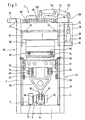
- thermoforming system 1 in a front view.
- the movable assemblies of the thermoforming unit 1 are arranged in a frame 2.
- the frame 2 can be constructed, for example, in Vorm of frame plates made of sheet steel, which are annealed stress-free.
- a bottom, that is arranged to the bottom cross member 4 connects the frame plates 2 and also serves as a bed for the bearings of the crankshaft drive 6.
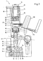
- the crankshaft drive 6 is driven in the variant shown here via an electric servo motor 8. Whose driving force is driven by a belt 10 and pulleys 12 and 14, which is particularly in Fig. 2 better visible in the lateral view.
- the crankshaft drive 6 is symmetrically mounted on both sides symmetrically in the variant shown here in relatively short lever arms 16, wherein the lever arms 16 are in turn hinged to a bearing block 18 mounted on the cross member 4.
- Fig. 1 As well as in Fig. 2
- the two-part mold 20 of the forming station of the thermoforming unit 1 is shown in the closed state.
- One in the upper part of the picture Fig. 1 and Fig. 2 recognizable Traverse 24 connects the two frame plates 2 above the two-part mold 20 and serves as the basis for a drive 26 for adjusting the upper tool table 28 with the attached upper tool 30.
- the drive 26 for adjusting the upper tool table 28 may, for example as Fine stroke be formed with threaded clearance compensation.
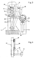
- a lower tool table 32 carries the lower tool 34 and is by means of appropriately designed linear guides 36 between the pivotable guide rails 38 of the pivotable guide rail assembly 40 (see. 3 and 4 ) of the guide device 42.
- Auswerferzylinder 44 and the upper connecting rod bearings 46 are attached.
- a chain transport 48 is shown, by means of which the plastic film 50 is fed to the two-part mold 20 and transported away after molding and punching the mold body not shown here, wherein the plastic film 50 preferably with appropriate means in the region of the two-part mold 20 bidirectionally planar tensioned.
- the upper tool table 28 is guided in correspondingly designed linear guides 52 between the frame plates 2.
- the lower tool 34 may for example have a mounting surface of 490 mm x 1040 mm.
- four rows of eight cavities for 32 moldings with a molding diameter of about 75 mm can be realized. This means a total punching length of all punched through edges of 7640 mm, which makes a total punching force of about 400 kN necessary.
- the upper tool 30 is attached, for example, not shown spacers on the upper tool table 28. Guide rails, not shown, facilitate the assembly of the tools.
- a thread play compensation 54 is used to compensate for game, for example, the Feinhubantrieb 26 of the upper tool table 28.
- the linear guides 36 for the lower tool table 32 have a backlash-free setting and ensure an exact guidance of the lower tool 34.
- the linear guides 52 of the upper tool table 28 have unspecified adjustable sliding guides on.
- the connecting rod 58 driven by the crankshaft drive 6, which may also be referred to as a connecting rod for the lifting drive of the lower tool table 32, is designed in the form of a triangle or Y-shaped in the variant shown here.
- the connecting rod 58 is articulated with a first connecting rod portion 60 on the eccentric shaft portion 62 of the crankshaft drive 6.
- the two in Fig. 1 and 2 upwardly facing arms 64 of the Y-shaped connecting rod 58 are hinged to the connecting rod bearings 46 of the lower tool table 32.
- These two upper connecting rod bearings 46 are here as possible arranged such that a deflection of the lower tool table 32 and its own weight can be kept as low as possible.
- the Y-shaped connecting rod 58 has at the lower connecting rod portion 60 of the variant shown here advantageously only one bearing, so that already satisfies a crank mechanism.
- crankshaft drive 6 is provided with a double bearing in a rigid construction.
- the related crank bearings may be split for ease of assembly.
- the crankshaft drive 6 is mounted centrally in lever arms 16, which form a kind of double rocker. This is in turn mounted with its right side by means of the bearing block 18 on the traverse 4.
- the punch drive 64 engages.
- the punch drive 64 consists for example of a hydraulic cylinder and an associated Hydraulic system, which generates a sudden punching stroke on the hydraulic cylinder, which is transmitted via the double rocker 16, the crankshaft drive 6, the connecting rod 58, the bearing 46 on the lower tool table 32 and thus on the lower tool 34.
- the drive of the crankshaft drive 6 can - as already mentioned above - as a lifting drive have a servo motor 8, which acts on the crankshaft drive 6 via gear, timing belt, sprocket drives or the like in low-play design.
- the closing and opening of the two-part mold 20 then corresponds to 160 ° rotation on the crankshaft.
- pivot lever 38 for pivotally receiving the lower tool table 32 have in the variant shown here, for example, the closer in Fig. 3 illustrated, designed as cam rollers, pivot lever side guides 66.
- the trained example as cam rollers lateral guides 66 of the pivot lever 38 run on not shown hardened rails and are free of play adjustable for exact guidance of the lower tool 34th
- a crank rod 68 is provided on both sides of the lower tool table 32.
- drive 70 for generating the pivoting movement of the lower tool 34 via the pivotable guide rails 38 may be provided on both guide rails 38 acting Kurbelstangenschwenkantrieb 68, which is driven for example by a servo geared motor 72 and a synchronizing shaft 74.
- pivot lever stop 76 is provided, as in Fig. 3 shown. This stop 76 for the pivot lever 38 is adjustable for exact positioning of the lower tool 32.
- the drive 84 for adjusting the upper tool table 28, which may be formed, for example, as a fine drive, not only serves for example for setting the punching stroke, but can also be used to turn on or turn off the punching stroke.
- Two in Fig. 1 and 2 only slightly visible threaded spindles 78 are driven, for example via worm gear 80 via a synchronizing shaft 82 by means of a geared motor 84.
- two thread clearance compensators 54 which are designed, for example, as pneumatic bellows cylinders, can pull the upper tool table 28 upwards via tie rods, not shown, in order to eliminate the backlash between the spindle and the nut.
- a pre-stretching unit 86 has, inter alia, in the variant shown here, a pre-stretching drive 88 in the form of a servo motor, which has an infeed drive 88 in the form of a servomotor Fig. 2 Not shown toothed belt drive and planetary roller screw, the mother is connected by releasable couplings with the Vorumblerplatte 90 and the prestretchers 92 disposed thereon on. In this case, the Vortierrantrieb also have a highly dynamic servo motor 88.
- FIG. 1 illustrated alternative variant of the Vorumblerantriebs of the pre-stretching unit 86, this may have a console 94 which carries a hydraulic cylinder 96 as Vorumblerantrieb.
- the hydraulic cylinder 96 is moved with the console 94 relative to the upper tool table 28 resting with this linear. The distance between the hydraulic cylinder 96 to the upper tool table 28 thus always remains constant.
- the hydraulic cylinder 96 is encapsulated by a housing 98 so that no hydraulic oil can escape even with minor leaks.
- a push rod 100 is hinged to the hydraulic cylinder 96 as in FIG Fig. 1 shown, and is articulated with her, the hydraulic cylinder 96 facing away from the end in the right variant of a rocker arm 102 in the variant shown here.
- the rocker arm 102 is pivotally supported by means of a bearing 104.
- the bearing 104 engages on a suitable bracket in turn on the upper tool table 28.
- the pre-stretching rod 106 is articulated, which communicates with the pre-stretching plate 90 and the pre-stretchers 92 arranged thereon.
- the hydraulic cylinder 96 for driving the pre-stretchers 92 may include a servo-controller that includes a programmable controller for the stroke of the cylinder 96.
- the required hydraulic unit can be arranged in the machine base.
- the Vorierstange 106 may be connected via a compensating coupling with the Vorumblerplatte 90 in the upper tool 30.
- the housing 98 for the hydraulic cylinder 96 not only serves to catch any leaks, but can also carry the servo control and also contain sensors or the like to report any leaks occurring and have means to dissipate them. The same applies to the hydraulic lines.
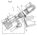
- the thermoforming plant I can be assigned a stacking device 108, which receives, stacks and removes the finished molded articles after ejection from the cavities of the lower tool 34.
- the stacking device 108 can, for example, have a rake 110 for removing the ejected molded bodies.
- FIG. 6 is another variant of the already in Fig. 1 to 5 Vorumblerantriebe 88 shown.
- a crank mechanism 140 acts via a push-pull rod 100 on a rocker arm 102, the here in Fig. 6 simplified dash-dotted line is shown to illustrate second different positions, namely the one position in the execution of the working stroke and thus lowering the Vorumbler 92 and the return stroke, ie when lifting the Vorumblerplatte 90 arranged Vorumbler 92.
- the rocker arm 102 which tilts about a pivot point in the bearing 104, which is designed to be transversely displaceable in the variant shown here, as indicated by the arrow 142, on the prestretch rod 106, which is articulated to the Vorstrekkerplatte 90.
- the stroke 146 can be varied in an advantageous manner and, in contrast, the stroke 148 of the pre-stretching drive can be kept constant.
- the downward working stroke, the pre-straightener 92 with the further arrow 150 and the relevant return stroke with the arrow 152 are marked.
- FIG. 7 is again in a simplified manner in a schematic representation of a possible embodiment of a Vorumblerantriebs 88 drive side closer shown.
- the crank mechanism 140 is supported on the housing side by means of a bearing 154.
- a transmission 156 and a clutch / brake combination 158 connect the crank drive 140 to a motor 160.
- Fig. 8 a further alternative embodiment of a Vorumblerantriebs 88 is shown in a schematically simplified sketch.
- the gearbox construction is essentially the same as in Fig. 6 discussed.
- crank mechanism 140 is in Fig. 8 a hydraulic cylinder 162 is provided, as for example in the in Fig. 1 to 5 hydraulic Vorstreckzylinder 96 discussed is the case.
- the fulcrum shift is again symbolized by the arrow 142.
- an electric motor 164 and an adjusting spindle 166 are provided.
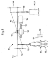
- FIG. 9 another variant of a prestretcher drive 88 is shown schematically.
- a hydraulic pre-stretch cylinder 96 or 162 serves to generate the force.
- This is connected to the push-pull rod 100 at point A.
- the push-pull rod 100 is in turn articulated at point B on the rocker arm 102.
- the rocker arm 102 is in turn articulated at point C on the prestretch rod 106.
- the Vorchirrstange 106 in turn is at point D with the Vorrowrplatte 90 hingedly connected.
- Vorumbler 92 are hinged, which in turn are mounted linearly displaceable in the upper tool 30.
- the upper tool 30 is attached to the upper tool table 28.
- the rocker arm 102 is rotatably supported about the point B0 in the bearing 104.
- the hydraulic cylinder 96 or 162 is arranged in front of and behind the upper tool 30.
- An alternative arrangement of the cylinder 96 or 162 adjacent to the tool 30 is also possible.
- the pre-stretchers 92 are in Fig. 9 shown in the parking position. Accordingly, the pre-stretchers 92 in the schematic sketch according to Fig. 10 shown in the extended position. For the rest, the presentation is similar Fig. 10 the in Fig. 9 shown variant of an exemplary embodiment of Vorsummerantriebes 88th
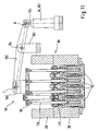
- FIG. 11 another alternative embodiment of a pre-stretch drive 88 is shown.
- This is similar to the one in Fig. 9 and 10 shown variant, however, has an alternative lever mechanism.
- longitudinal holes are provided in the articulation points B and C, which allow an axial displaceability of these articulation points, so that the hydraulic cylinder 96 or 162 can be hinged directly to the rocker arm 102 at point B, so that the thrust drawbar 100 can be dispensed with.
- the Vorrowrstange 106 in which the former pivot points C and D coincide in common pivot point C, in which the rocker arm 102 is connected directly to a suitably designed shoulder or storage 168 with the Vorumble 90.
- the heated plastic film 50 is pressed into the mold cavities or cavities of the lower tool 34 with the aid of the pre-stretchers 92, which are mounted in a linearly displaceable manner in the upper tool 30, for molding the cup-shaped moldings, for example.
- the film is applied to the walls of the mold cavities or cavities.
- the Vorumbler 92 are doing again in their parking position (see. Fig. 9 ) in the upper tool 30 (see arrows 150 and 152 in FIG Fig. 6 and 8th ).
- a Vorumblerantrieb 88 is proposed with high dynamics.
- a duration of at most 300 ms, preferably at most 250 ms and particularly preferably at most 200 ms is achieved.
- the in Fig. 6 to 11 discussed Vorumblerantrieb 88 able to the pre-stretching of the plastic film 50 required forces produce.
- the sum of the forces acting on the individual Vorumbler 92 forces can be up to 50,000 N depending on the embodiment.
- a pretensioner drive 88 is provided with a hydraulic cylinder 96 or 162 for generating the necessary forces.
- the pre-stretchers 92 are in the illustrations according to Fig. 9 to 11 by means of a pre-stretching punch rod 170 with a bridge or the so-called. Vorumble 90 firmly connected.
- the stamping rods 190 run in a straight manner guided in guide bushes 172 of the upper tool 30, so that the entire pre-stretching unit 86 can be moved vertically.
- the drive of the Vorumbler 92 takes place as discussed above with the aid of the hydraulic cylinder 96 and 162 is - as in Fig. 1 to 5 shown - firmly connected to a bracket 94, which in turn is supported by the upper tool table 28.
- the linear movement of the piston rod 174 is first transmitted through the coupling or push-pull rod 100 with the pivot joints A and B on the rocker arm 102.
- the rocker arm 102 is - as discussed above - rotatably supported at the point B 0 relative to the upper tool table 28.
- the coupling or Vorumblerstange 106 with the pivot joints C and D finally transmits the movement of the rocker arm 102 to the pre-stretching unit 86th
- transmission 88 can be varied in many forms.
- the movement of the rocker arm 102 can be transmitted to the pre-stretching unit 86 by means of a bolt and a link.
- the cylinder 96 or 162 may be alternatively hinged only to the fixed connection with the bracket 94 relative to the bracket 94 and thus held pivotally.
- the present invention thus advantageously provides a thermoforming plant for the production of molded articles made of plastic film, such as cups, containers, lids, food wrappers or the like, with a forming station having a two-part mold.
- the two-part mold has an adjustably lockable upper tool table with an upper tool with pre-stretchers mounted movably therein and a movable lower tool table with a lower tool with cavities.
- the movable lower tool table is guided by means of a guide device and by a drive device relative to the upper tool table on this and movable away therefrom.
- the upper tool table has a first drive device assigned to it for setting up the upper tool table in its position relative to the top dead center of the lower tool table in coordination with the molding to be produced in each case.
- the upper tool table has a second drive device assigned to it for driving the pre-stretchers movably mounted in the upper tool.
- the present invention proposes an economical process for the production of molded plastic film.
- the thermoforming machine can be used to process plastic films made of PP, PS, PE, PET, ABS or PVC.
- the thermoforming system as a film web supplied plastic film can have a film web width of at least 250 mm to 750 mm at a film web thickness of at least 0.3 mm to 4 mm.
- the mold surface available between the upper and lower molds is at least 700 mm x 450 mm.
- the maximum closing force is at least 400 kN with a maximum cutting length of at least 8400 mm.
Landscapes
- Engineering & Computer Science (AREA)
- Mechanical Engineering (AREA)
- Blow-Moulding Or Thermoforming Of Plastics Or The Like (AREA)
- Moulds For Moulding Plastics Or The Like (AREA)
- Shaping Of Tube Ends By Bending Or Straightening (AREA)
Claims (9)
- Installation de thermoformage (1) servant à fabriquer des corps moulés en feuille de plastique (50), tels que des pots, récipients, couvercles, emballages pour denrées alimentaires ou similaires, équipée d'une station de façonnage présentant un outil de moulage (20) en deux parties,
sachant que l'outil de moulage (20) en deux parties présente une table à outil supérieure (28) pouvant être fixée de manière ajustable et dotée d'un outil supérieur (30), dans lequel sont logées de manière mobile des préétireuses (92), et une table à outil inférieure (32) mobile dotée d'un outil inférieur (34) à cavités,
sachant que la table à outil inférieure (32) mobile est guidée par l'intermédiaire d'un dispositif de guidage (42) et peut être déplacée par un premier dispositif d'entraînement, par rapport à la table à outils supérieure (28) de manière à s'en approcher ou à s'en éloigner, sachant que
la table à outil supérieure (28) présente un premier dispositif d'entraînement (26) qui lui est associé et qui sert à amener la table à outil supérieure (28) dans sa position par rapport au point mort supérieur de la table à outil inférieure (32) en correspondance avec le corps moulé à fabriquer respectivement, et
sachant que la table à outil supérieure (28) présente un deuxième dispositif d'entraînement (88) qui lui est associé et qui sert à entraîner les préétireuses (92) logées de manière mobile dans l'outil supérieur,
caractérisée en ce que
le premier dispositif d'entraînement pour la table à outil inférieure (32) est réalisé comme un entraînement à vilebrequin (6),
en ce que la table à outil inférieure (32) peut être soulevée conjointement avec son premier dispositif d'entraînement à l'intérieur du dispositif de guidage (42) guidant ladite table au moyen d'un deuxième dispositif d'entraînement réalisé comme un entraînement d'estampage (64) et servant à générer une course d'estampage brusque, et
en ce que les préétireuses (92) peuvent être entraînées au moyen du deuxième dispositif d'entraînement de la table à outil supérieure (28) de telle manière qu'une course (146) d'au moins 120 mm peut être réalisée en moins de 300 msec. - Installation de thermoformage (1) selon la revendication 1, caractérisée en ce que les préétireuses (92) peuvent être entraînées au moyen d'un deuxième dispositif d'entraînement de la table à outil supérieure (28) de telle manière qu'une course (146) d'au moins 120 mm peut être réalisée en moins de 200 msec.
- Installation de thermoformage (1) selon la revendication 1 ou 2, caractérisée en ce que le deuxième dispositif d'entraînement (88) de la table à outil supérieure (28) servant à entraîner les préétireuses (92) présente un entraînement à vilebrequin (140) entraîné au moyen d'un servomoteur électrique (160).
- Installation de thermoformage (1) selon la revendication 1 ou 2, caractérisée en ce que le deuxième dispositif d'entraînement (88) de la table à outil supérieure (28) servant à entraîner les préétireuses (92) présente un entraînement hydraulique (96, 162).
- Installation de thermoformage (1) selon la revendication 1, caractérisée en ce que le premier dispositif d'entraînement (26) servant à placer la table à outil supérieure est un servomoteur électrique (84).
- Installation de thermoformage (1) selon l'une quelconque des revendications 1 à 5, caractérisée en ce que le premier dispositif d'entraînement (26) servant à placer la table à outil supérieure (28) coopère par l'intermédiaire d'un arbre de synchronisation (82) avec des vis sans fin/roues disposées sur celui-ci, dotées de deux broches d'ajustage (78), lesquelles agissent de leur côté sur la table à outil supérieure (28) de telle manière que cette dernière peut effectuer des mouvements de va-et-vient verticalement dans son orientation horizontale de sorte que la table à outil supérieure (28) peut être ajustée sur le corps moulé à fabriquer respectivement.
- Installation de thermoformage (1) selon l'une quelconque des revendications 1 à 6, caractérisée en ce que le deuxième dispositif d'entraînement (88) agit par l'intermédiaire d'une barre de traction/cisaillement (100), d'un levier de basculement (102) et d'une barre de pression (106) sur la préétireuse (92) dans l'outil supérieur (30), de préférence par l'intermédiaire d'un point de rotation B0 du levier de basculement (104), réalisé de manière coulissable (142).
- Procédé de fabrication de corps moulés en feuille de plastique, tels que des pots, des récipients, des couvercles, des emballages pour denrées alimentaires ou similaires, au moyen d'une installation de thermoformage (1), comportant les étapes suivantes consistant à :- fournir une installation de thermoformage (50) selon le préambule de la revendication 1 ;- amener la feuille de plastique (50) dans l'outil de formage (20) en deux parties par l'intermédiaire d'un transport par chaîne (48) ;- tendre la feuille de plastique (50) dans la zone de l'outil de formage (20) ;- fermer l'outil de formage (20) en guidant la table à outil inférieure (32) mobile par l'intermédiaire du dispositif de guidage (42), et l'entraîner par l'intermédiaire d'un premier dispositif d'entraînement de telle manière que ladite table est déplacée par rapport à la table à outil supérieur (28) de manière à s'en approcher ;- fabriquer les corps moulés lorsque l'outil de formage (20) est fermé ;- ouvrir l'outil de formage (20) en guidant la table à outil inférieure (32) mobile par l'intermédiaire du dispositif de guidage (42), et l'entraîner par l'intermédiaire du premier dispositif d'entraînement de telle manière que ladite table est déplacée par rapport à la table à outil supérieure (28) de manière à s'en éloigner ; et- éjecter les corps moulés éventuellement dans un dispositif d'empilage, sachant que :- la table à outil supérieure (28) est placée par l'intermédiaire d'un premier dispositif d'entraînement (26) qui lui est associé dans sa position par rapport au point mort supérieur de la table à outil inférieure (32) en correspondance avec le corps moulé à fabriquer respectivement ;caractérisé en ce que- la table à outil inférieure (32) est entraînée au moyen du premier dispositif d'entraînement réalisé comme un entraînement à vilebrequin (6) ;- la table à outil inférieure (32) est levée puis abaissée avec son premier dispositif d'entraînement à l'intérieur du dispositif de guidage (42) la guidant au moyen d'un deuxième dispositif d'entraînement réalisé comme un entraînement d'estampage (64) servant à générer une course d'estampage brutale ; et- les préétireuses (92) logées de manière mobile dans l'outil supérieur (30) sont entraînées au moyen d'un deuxième dispositif d'entraînement (88) de la table à outil supérieure (28), à savoir de telle manière qu'une course (146) d'au moins 120 mm est réalisée en moins de 300 msec.
- Procédé selon la revendication 8, caractérisé en ce que les préétireuses (92) logées de manière mobile dans l'outil supérieur (30) sont entraînées au moyen du deuxième dispositif d'entraînement (88) de la table à outil supérieure (28) de telle manière qu'une course (146) d'au moins 120 mm est réalisée en moins de 200 msec.
Priority Applications (1)
| Application Number | Priority Date | Filing Date | Title |
|---|---|---|---|
| SI200332233T SI2105278T1 (sl) | 2002-04-25 | 2003-04-17 | Naprava za toplotno preoblikovanje za izdelavo oblikovanih teles iz folije iz umetne snovi kot tudi postopek izdelave le-teh |
Applications Claiming Priority (5)
| Application Number | Priority Date | Filing Date | Title |
|---|---|---|---|
| DE10218511A DE10218511B4 (de) | 2002-04-25 | 2002-04-25 | Thermoformanlage zur Herstellung von Formkörpern aus Kunststofffolie, sowie Verfahren zu deren Herstellung |
| DE20206601U DE20206601U1 (de) | 2002-04-25 | 2002-04-25 | Thermoformanlage zur Herstellung von Formkörpern aus Kunststoffolie |
| DE10218486A DE10218486B4 (de) | 2002-04-25 | 2002-04-25 | Thermoformanlage zur Herstellung von Formkörpern aus Kunststoffolie, sowie Verfahren zu deren Herstellung |
| DE20206600U DE20206600U1 (de) | 2002-04-25 | 2002-04-25 | Thermoformanlage zur Herstellung von Formkörpern aus Kunststoffolie |
| EP03725052A EP1497100B1 (fr) | 2002-04-25 | 2003-04-17 | Installation de thermoformage et procede pour produire des corps moules en film de matiere plastique |
Related Parent Applications (3)
| Application Number | Title | Priority Date | Filing Date |
|---|---|---|---|
| EP03725052.9 Division | 2003-04-17 | ||
| EP03725052A Division EP1497100B1 (fr) | 2002-04-25 | 2003-04-17 | Installation de thermoformage et procede pour produire des corps moules en film de matiere plastique |
| WOPCT/EP03/04028 Previously-Filed-Application | 2003-04-17 |
Publications (3)
| Publication Number | Publication Date |
|---|---|
| EP2105278A2 EP2105278A2 (fr) | 2009-09-30 |
| EP2105278A3 EP2105278A3 (fr) | 2010-10-27 |
| EP2105278B1 true EP2105278B1 (fr) | 2012-10-17 |
Family
ID=29273675
Family Applications (3)
| Application Number | Title | Priority Date | Filing Date |
|---|---|---|---|
| EP09006715A Expired - Lifetime EP2105278B1 (fr) | 2002-04-25 | 2003-04-17 | Installation de thermoformage destinée à la fabrication de corps en feuille de matière plastique, et son procédé de fabrication |
| EP03725052A Expired - Lifetime EP1497100B1 (fr) | 2002-04-25 | 2003-04-17 | Installation de thermoformage et procede pour produire des corps moules en film de matiere plastique |
| EP03717309A Expired - Lifetime EP1497099B1 (fr) | 2002-04-25 | 2003-04-17 | Installation de thermoformage pour la production de corps faconnes a partir d'un film de plastique, et procede de production de tels corps |
Family Applications After (2)
| Application Number | Title | Priority Date | Filing Date |
|---|---|---|---|
| EP03725052A Expired - Lifetime EP1497100B1 (fr) | 2002-04-25 | 2003-04-17 | Installation de thermoformage et procede pour produire des corps moules en film de matiere plastique |
| EP03717309A Expired - Lifetime EP1497099B1 (fr) | 2002-04-25 | 2003-04-17 | Installation de thermoformage pour la production de corps faconnes a partir d'un film de plastique, et procede de production de tels corps |
Country Status (11)
| Country | Link |
|---|---|
| US (2) | US7560063B2 (fr) |
| EP (3) | EP2105278B1 (fr) |
| AT (2) | ATE504416T1 (fr) |
| AU (2) | AU2003222300A1 (fr) |
| DE (1) | DE50313599D1 (fr) |
| DK (3) | DK2105278T3 (fr) |
| ES (1) | ES2393165T3 (fr) |
| PL (2) | PL206839B1 (fr) |
| PT (2) | PT2105278E (fr) |
| SI (3) | SI2105278T1 (fr) |
| WO (2) | WO2003099541A1 (fr) |
Families Citing this family (19)
| Publication number | Priority date | Publication date | Assignee | Title |
|---|---|---|---|---|
| DE102006003851B4 (de) * | 2006-01-26 | 2020-06-04 | Kiefel Gmbh | Vorrichtung zum Formen, Stanzen und Stapeln von tiefgezogenen Teilen aus thermoplastischen Kunststoffen |
| DE102006003852A1 (de) * | 2006-01-26 | 2007-08-02 | Kiefel Ag | Vorrichtung zum Formen, Stanzen und Stapeln von tiefgezogenen Teilen aus thermoplastischem Kunststoff |
| ITMO20060349A1 (it) * | 2006-10-30 | 2008-04-30 | Sarong Spa | Apparato e metodo di centratura stampa |
| ITMI20070763A1 (it) * | 2007-04-16 | 2008-10-17 | T F T S R L | Dispositivo di movimentazione del piano mobile di una pressa, particolarmente per la produzione di articoli in plastica |
| EP2110220A3 (fr) * | 2008-04-14 | 2010-08-04 | Fill Gesellschaft m.b.H. | Dispositif de fabrication d'éléments de formage, notamment d'éléments de formage en mousse |
| DE102008032806A1 (de) * | 2008-07-11 | 2010-01-14 | Gabler Thermoform Gmbh & Co. Kg | Vorrichtung zum Herstellen von Hohlkörpern aus thermoplastisch verformbaren Kunststoff-Folien |
| DE102009059068B4 (de) * | 2009-01-19 | 2020-09-17 | Gabler Thermoform Gmbh & Co. Kg | Vorrichtung zum Formen, Stanzen und Stapeln von tiefgezogenen Teilen aus thermoplastischer Kunststofffolie |
| US20100310696A1 (en) * | 2009-06-05 | 2010-12-09 | Schlepp Brian D | Pre-loading mechanism for a tilting platen in a thermoforming press |
| US20100310703A1 (en) * | 2009-06-05 | 2010-12-09 | Schlepp Brian D | Thermoformer drive and tilt system |
| BRPI0902159E2 (pt) * | 2009-06-18 | 2011-03-09 | Jorge Lakatos | sistema de acionamento de mesa de prensas |
| DE102010009536A1 (de) * | 2010-02-26 | 2011-09-01 | Cfs Germany Gmbh | Verfahren zum Wechsel des Ober- und Unterwerkzeugs einer Verpackungsmaschine |
| DE102010056319B4 (de) * | 2010-12-27 | 2013-09-12 | Multivac Sepp Haggenmüller Gmbh & Co. Kg | Verpackungsmaschine mit einem anhebbaren und absenkbaren Werkzeug |
| US8834977B2 (en) | 2011-10-20 | 2014-09-16 | Scholle Corporation | Coextruded film and bags made therefrom suitable for bag in box containers and method of manufacturing the coextruded film |
| ITMI20122022A1 (it) * | 2012-11-28 | 2014-05-29 | Wm Wrapping Machinery Sa | Macchina termo-formatrice con piano mobile basculante |
| CN103470711B (zh) * | 2013-09-25 | 2018-01-05 | 艾同近 | 连体鞋盒成形机移动凸轮机构 |
| PL240263B1 (pl) * | 2018-10-22 | 2022-03-07 | Jezewska Elzbieta Promet Plast Spolka Cywilna Elzbieta Jezewska Andrzej Jezewski | Sposób wytwarzania pojemnika z tworzywa sztucznego, zwłaszcza kubka medycznego |
| CN110419871B (zh) * | 2019-08-16 | 2021-03-26 | 江西金钱豹保险设备集团有限公司 | 一种智能防潮降温密集架 |
| CN111890667B (zh) * | 2020-08-01 | 2024-11-01 | 王昌佑 | 热成型机的上升与下降会合高速接卸料传送装置 |
| CN115008725B (zh) * | 2022-07-22 | 2024-02-20 | 平阳县力泰机械有限公司 | 塑料容器的成型设备 |
Family Cites Families (19)
| Publication number | Priority date | Publication date | Assignee | Title |
|---|---|---|---|---|
| US2282423A (en) | 1939-09-15 | 1942-05-12 | Plax Corp | Process and apparatus for forming articles from organic plastic material |
| DE2146217A1 (de) | 1971-09-16 | 1973-03-22 | Michelfelder Fa Karl | Tiefziehmaschine fuer kunststofffolien |
| US4140457A (en) * | 1975-09-02 | 1979-02-20 | Sumitomo Bakelite Company Limited | Method for producing transparent plastic molded articles and thermoforming apparatus therefor |
| IT1053243B (it) | 1975-10-09 | 1981-08-31 | Omv Spa | Sistema di produzione di oggetti cavi finiti picavati da un nastro di materiale plastico per termo formatura |
| DE3346628C2 (de) | 1983-12-23 | 1986-03-27 | Adolf Illig Maschinenbau Gmbh & Co, 7100 Heilbronn | Vorrichtung zum Formen, Stanzen und Stapeln von tiefgezogenen Teilen aus thermoplastischem Kunststoff |
| GB2142272B (en) * | 1983-05-28 | 1986-04-23 | Illig Maschinenbau Adolf | Moulding apparatus |
| JPS60115419A (ja) | 1983-11-28 | 1985-06-21 | Fanuc Ltd | 射出成形機におけるクランク式型締機構 |
| US5002479A (en) * | 1989-05-30 | 1991-03-26 | John Brown Inc. | Apparatus for adjusting the shut height of a mold in a differential pressure forming machine |
| JP2670171B2 (ja) | 1990-04-18 | 1997-10-29 | 住友重機械工業株式会社 | 封止用金型の型締装置 |
| DE19716655C2 (de) | 1997-04-21 | 2002-11-21 | Gabler Gmbh Maschbau | Vorrichtung zum Formen, Stanzen und Stapeln von tiefgezogenen Teilen aus thermoplastischem Kunststoff |
| DE19724963C1 (de) * | 1997-06-12 | 1999-01-21 | Illig Maschinenbau Adolf | Form- oder Stanzstation |
| US6135756A (en) | 1997-06-13 | 2000-10-24 | Arends; Albert W. | Differential pressure forming, trimming and stacking apparatus |
| DE19917472C1 (de) * | 1999-04-17 | 2000-12-07 | Illig Maschinenbau Adolf | Antriebseinrichtung für einen Streckhelfer zum mechanischen Verformen einer erwärmten Kunststoffolie oder -platte |
| DE19921668C1 (de) * | 1999-05-11 | 2001-01-04 | Illig Maschinenbau Adolf | Verfahren zum Bewegen eines Schwenktisches in einer Vorrichtung zum Formen und Ausstanzen von Behältern aus einer thermoplastischen Kunststoffolie und Vorrichtung zur Durchführung des Verfahrens |
| US6200122B1 (en) | 1999-08-03 | 2001-03-13 | Brown Machine, Llc. | Thermoforming apparatus with improved press |
| DE19948768C1 (de) | 1999-10-09 | 2001-03-08 | Illig Maschinenbau Adolf | Vorrichtung zum Formen und Ausstanzen von Behältern aus einer thermoplastischen Kunststoffolie |
| DE10017042B4 (de) * | 2000-04-05 | 2004-09-30 | Adolf Illig Maschinenbau Gmbh & Co.Kg | Form-/Stanzwerkzeug zum Herstellen von Behältern aus einer thermoplastischen Kunststofffolie |
| DE10100119C1 (de) * | 2001-01-03 | 2002-06-20 | Illig Maschinenbau Adolf | Kombinierte Form-/Stanzstation zum Formen und Ausstanzen von Behältern aus einer Folienbahn aus thermoplastischem Kunststoff |
| DE10157134B4 (de) | 2001-11-21 | 2005-07-07 | Adolf Illig Maschinenbau Gmbh & Co.Kg | Vorrichtung zum Formen und Ausstanzen von Behältern aus einer Folienbahn aus thermoplastischem Kunststoff |
-
2003
- 2003-04-17 DK DK09006715.8T patent/DK2105278T3/da active
- 2003-04-17 PT PT09006715T patent/PT2105278E/pt unknown
- 2003-04-17 AU AU2003222300A patent/AU2003222300A1/en not_active Abandoned
- 2003-04-17 EP EP09006715A patent/EP2105278B1/fr not_active Expired - Lifetime
- 2003-04-17 AU AU2003227642A patent/AU2003227642A1/en not_active Abandoned
- 2003-04-17 US US10/512,259 patent/US7560063B2/en not_active Expired - Fee Related
- 2003-04-17 DK DK03717309.3T patent/DK1497099T3/da active
- 2003-04-17 US US10/512,258 patent/US7332121B2/en not_active Expired - Fee Related
- 2003-04-17 SI SI200332233T patent/SI2105278T1/sl unknown
- 2003-04-17 PL PL371246A patent/PL206839B1/pl not_active IP Right Cessation
- 2003-04-17 DE DE50313599T patent/DE50313599D1/de not_active Expired - Lifetime
- 2003-04-17 EP EP03725052A patent/EP1497100B1/fr not_active Expired - Lifetime
- 2003-04-17 SI SI200332059T patent/SI1497100T1/sl unknown
- 2003-04-17 EP EP03717309A patent/EP1497099B1/fr not_active Expired - Lifetime
- 2003-04-17 WO PCT/EP2003/004029 patent/WO2003099541A1/fr not_active Ceased
- 2003-04-17 PL PL371250A patent/PL206716B1/pl not_active IP Right Cessation
- 2003-04-17 PT PT03725052T patent/PT1497100E/pt unknown
- 2003-04-17 ES ES09006715T patent/ES2393165T3/es not_active Expired - Lifetime
- 2003-04-17 AT AT03717309T patent/ATE504416T1/de active
- 2003-04-17 SI SI200332015T patent/SI1497099T1/sl unknown
- 2003-04-17 DK DK03725052.9T patent/DK1497100T3/da active
- 2003-04-17 WO PCT/EP2003/004028 patent/WO2003091001A1/fr not_active Ceased
- 2003-04-17 AT AT03725052T patent/ATE517731T1/de active
Also Published As
| Publication number | Publication date |
|---|---|
| ATE504416T1 (de) | 2011-04-15 |
| ES2393165T3 (es) | 2012-12-19 |
| US20050230873A1 (en) | 2005-10-20 |
| DK2105278T3 (da) | 2012-11-26 |
| EP1497099B1 (fr) | 2011-04-06 |
| WO2003091001A1 (fr) | 2003-11-06 |
| SI1497099T1 (sl) | 2011-09-30 |
| EP1497099A1 (fr) | 2005-01-19 |
| US7560063B2 (en) | 2009-07-14 |
| DE50313599D1 (de) | 2011-05-19 |
| PT2105278E (pt) | 2012-10-30 |
| EP2105278A3 (fr) | 2010-10-27 |
| EP1497100B1 (fr) | 2011-07-27 |
| EP1497100A1 (fr) | 2005-01-19 |
| AU2003227642A1 (en) | 2003-11-10 |
| SI2105278T1 (sl) | 2013-02-28 |
| PL371250A1 (en) | 2005-06-13 |
| WO2003099541A1 (fr) | 2003-12-04 |
| PT1497100E (pt) | 2011-08-11 |
| PL371246A1 (en) | 2005-06-13 |
| DK1497099T3 (da) | 2011-07-11 |
| SI1497100T1 (sl) | 2011-11-30 |
| PL206839B1 (pl) | 2010-09-30 |
| AU2003222300A1 (en) | 2003-12-12 |
| ATE517731T1 (de) | 2011-08-15 |
| DK1497100T3 (da) | 2011-09-12 |
| EP2105278A2 (fr) | 2009-09-30 |
| US7332121B2 (en) | 2008-02-19 |
| PL206716B1 (pl) | 2010-09-30 |
| US20050244534A1 (en) | 2005-11-03 |
Similar Documents
| Publication | Publication Date | Title |
|---|---|---|
| EP2105278B1 (fr) | Installation de thermoformage destinée à la fabrication de corps en feuille de matière plastique, et son procédé de fabrication | |
| EP4067050B1 (fr) | Procédé de formage et/ou de revêtement d'un élément feuille | |
| EP1832408A2 (fr) | Machine de formage thermique avec mécanisme à genouillère | |
| DE102008051026A1 (de) | Transportmittel und Verpackungsmaschine für Folienbreitenanpassung | |
| EP2086844A1 (fr) | Machine d'emballage à entraînement pneumatique/hydraulique ajustable | |
| EP2915651B1 (fr) | Procédé de fabrication de corps creux en matière plastique formés par soufflage et tête d'extrusion multiple permettant de réaliser le procédé | |
| EP0330914A1 (fr) | Dispositif d'éjection des pièces hors des matrices dans une presse de formage | |
| DE10218486B4 (de) | Thermoformanlage zur Herstellung von Formkörpern aus Kunststoffolie, sowie Verfahren zu deren Herstellung | |
| DE69101374T2 (de) | Verpackungsmaschine und -verfahren mit servomotor für schrittweisen antrieb. | |
| DE10218511B4 (de) | Thermoformanlage zur Herstellung von Formkörpern aus Kunststofffolie, sowie Verfahren zu deren Herstellung | |
| DE4033534C2 (de) | Vorrichtung zum Formen, Stanzen und Stapeln von tiefgezogenen Teilen aus thermoplastischem Kunststoff | |
| EP1582333B1 (fr) | Procédé et dispositif pour le thermoformage et découpage de récipients d'une feuille thermoplastique | |
| EP2052843B1 (fr) | Procédé de fonctionnement d'un dispositif destiné à la fabrication de pièces de formage à partir d'une feuille de matière synthétique thermoplastique | |
| EP0787111B1 (fr) | Procede de fabrication d'articles moules en verre, par moulage par compression et dispositif specialement approprie pour la mise en oeuvre de ce procede | |
| EP1613462B1 (fr) | Appareil de moulage avec un dispositif pour déplacer les moules | |
| DE20206601U1 (de) | Thermoformanlage zur Herstellung von Formkörpern aus Kunststoffolie | |
| EP1613461B1 (fr) | Ensemble moule | |
| DE20206600U1 (de) | Thermoformanlage zur Herstellung von Formkörpern aus Kunststoffolie | |
| WO2002049788A1 (fr) | Presse a forger dotee d'un dispositif de reglage situe cote matrice | |
| EP4344853A1 (fr) | Station de formage ou station de poinçonnage ou station de formage-poinçonnage combinée ainsi qu'installation de thermoformage | |
| DE2161247C3 (de) | Vorrichtung zum Herstellen von Hohlkörpern | |
| RU2291053C2 (ru) | Термоформовочная установка для изготовления формованных изделий из полимерной пленки, а также способ их изготовления | |
| EP0983832A1 (fr) | Procédé et appareil pour ouvrir ou fermer un moule d'une machine de moulage par injection | |
| DE19811403A1 (de) | Vorrichtung zum Herstellen eines Verzehrgutes | |
| EP4594080A1 (fr) | Dispositif de production de corps creux |
Legal Events
| Date | Code | Title | Description |
|---|---|---|---|
| PUAI | Public reference made under article 153(3) epc to a published international application that has entered the european phase |
Free format text: ORIGINAL CODE: 0009012 |
|
| AC | Divisional application: reference to earlier application |
Ref document number: 1497100 Country of ref document: EP Kind code of ref document: P |
|
| AK | Designated contracting states |
Kind code of ref document: A2 Designated state(s): AT BE BG CH CY CZ DE DK EE ES FI FR GB GR HU IE IT LI LU MC NL PT RO SE SI SK TR |
|
| PUAL | Search report despatched |
Free format text: ORIGINAL CODE: 0009013 |
|
| AK | Designated contracting states |
Kind code of ref document: A3 Designated state(s): AT BE BG CH CY CZ DE DK EE ES FI FR GB GR HU IE IT LI LU MC NL PT RO SE SI SK TR |
|
| RIC1 | Information provided on ipc code assigned before grant |
Ipc: B29C 51/04 20060101AFI20090819BHEP Ipc: B29C 51/26 20060101ALI20100922BHEP Ipc: B29C 51/46 20060101ALI20100922BHEP Ipc: B29C 51/38 20060101ALI20100922BHEP |
|
| 17P | Request for examination filed |
Effective date: 20110427 |
|
| 17Q | First examination report despatched |
Effective date: 20120229 |
|
| GRAP | Despatch of communication of intention to grant a patent |
Free format text: ORIGINAL CODE: EPIDOSNIGR1 |
|
| RIC1 | Information provided on ipc code assigned before grant |
Ipc: B29C 51/22 20060101ALI20120404BHEP Ipc: B29C 51/38 20060101ALI20120404BHEP Ipc: B29L 31/56 20060101ALI20120404BHEP Ipc: B29C 51/04 20060101AFI20120404BHEP Ipc: B29C 51/46 20060101ALI20120404BHEP Ipc: B29C 51/26 20060101ALI20120404BHEP |
|
| RTI1 | Title (correction) |
Free format text: THERMOFORMING ASSEMBLY FOR THE MANUFACTURE OF PLASTIC PARTS MADE OF PLASTIC FOILS AND MANUFACTURING METHOD THEREFORE |
|
| GRAS | Grant fee paid |
Free format text: ORIGINAL CODE: EPIDOSNIGR3 |
|
| GRAA | (expected) grant |
Free format text: ORIGINAL CODE: 0009210 |
|
| AC | Divisional application: reference to earlier application |
Ref document number: 1497100 Country of ref document: EP Kind code of ref document: P |
|
| AK | Designated contracting states |
Kind code of ref document: B1 Designated state(s): AT BE BG CH CY CZ DE DK EE ES FI FR GB GR HU IE IT LI LU MC NL PT RO SE SI SK TR |
|
| REG | Reference to a national code |
Ref country code: GB Ref legal event code: FG4D Free format text: NOT ENGLISH |
|
| REG | Reference to a national code |
Ref country code: PT Ref legal event code: SC4A Free format text: AVAILABILITY OF NATIONAL TRANSLATION Effective date: 20121018 |
|
| REG | Reference to a national code |
Ref country code: CH Ref legal event code: EP |
|
| REG | Reference to a national code |
Ref country code: IE Ref legal event code: FG4D Free format text: LANGUAGE OF EP DOCUMENT: GERMAN |
|
| REG | Reference to a national code |
Ref country code: AT Ref legal event code: REF Ref document number: 579682 Country of ref document: AT Kind code of ref document: T Effective date: 20121115 |
|
| REG | Reference to a national code |
Ref country code: DK Ref legal event code: T3 |
|
| REG | Reference to a national code |
Ref country code: DE Ref legal event code: R096 Ref document number: 50314546 Country of ref document: DE Effective date: 20121213 |
|
| REG | Reference to a national code |
Ref country code: ES Ref legal event code: FG2A Ref document number: 2393165 Country of ref document: ES Kind code of ref document: T3 Effective date: 20121219 |
|
| REG | Reference to a national code |
Ref country code: SE Ref legal event code: TRGR |
|
| REG | Reference to a national code |
Ref country code: NL Ref legal event code: T3 |
|
| REG | Reference to a national code |
Ref country code: SK Ref legal event code: T3 Ref document number: E 13322 Country of ref document: SK |
|
| PG25 | Lapsed in a contracting state [announced via postgrant information from national office to epo] |
Ref country code: CY Free format text: LAPSE BECAUSE OF FAILURE TO SUBMIT A TRANSLATION OF THE DESCRIPTION OR TO PAY THE FEE WITHIN THE PRESCRIBED TIME-LIMIT Effective date: 20121017 Ref country code: GR Free format text: LAPSE BECAUSE OF FAILURE TO SUBMIT A TRANSLATION OF THE DESCRIPTION OR TO PAY THE FEE WITHIN THE PRESCRIBED TIME-LIMIT Effective date: 20130118 |
|
| PG25 | Lapsed in a contracting state [announced via postgrant information from national office to epo] |
Ref country code: BG Free format text: LAPSE BECAUSE OF FAILURE TO SUBMIT A TRANSLATION OF THE DESCRIPTION OR TO PAY THE FEE WITHIN THE PRESCRIBED TIME-LIMIT Effective date: 20130117 Ref country code: EE Free format text: LAPSE BECAUSE OF FAILURE TO SUBMIT A TRANSLATION OF THE DESCRIPTION OR TO PAY THE FEE WITHIN THE PRESCRIBED TIME-LIMIT Effective date: 20121017 |
|
| PLBE | No opposition filed within time limit |
Free format text: ORIGINAL CODE: 0009261 |
|
| STAA | Information on the status of an ep patent application or granted ep patent |
Free format text: STATUS: NO OPPOSITION FILED WITHIN TIME LIMIT |
|
| PG25 | Lapsed in a contracting state [announced via postgrant information from national office to epo] |
Ref country code: RO Free format text: LAPSE BECAUSE OF FAILURE TO SUBMIT A TRANSLATION OF THE DESCRIPTION OR TO PAY THE FEE WITHIN THE PRESCRIBED TIME-LIMIT Effective date: 20121017 |
|
| 26N | No opposition filed |
Effective date: 20130718 |
|
| REG | Reference to a national code |
Ref country code: HU Ref legal event code: AG4A Ref document number: E016620 Country of ref document: HU |
|
| REG | Reference to a national code |
Ref country code: DE Ref legal event code: R097 Ref document number: 50314546 Country of ref document: DE Effective date: 20130718 |
|
| PG25 | Lapsed in a contracting state [announced via postgrant information from national office to epo] |
Ref country code: MC Free format text: LAPSE BECAUSE OF FAILURE TO SUBMIT A TRANSLATION OF THE DESCRIPTION OR TO PAY THE FEE WITHIN THE PRESCRIBED TIME-LIMIT Effective date: 20121017 |
|
| REG | Reference to a national code |
Ref country code: CH Ref legal event code: PL |
|
| REG | Reference to a national code |
Ref country code: SK Ref legal event code: MM4A Ref document number: E 13322 Country of ref document: SK Effective date: 20130417 |
|
| REG | Reference to a national code |
Ref country code: PT Ref legal event code: MM4A Free format text: LAPSE DUE TO NON-PAYMENT OF FEES Effective date: 20140117 |
|
| REG | Reference to a national code |
Ref country code: IE Ref legal event code: MM4A |
|
| PG25 | Lapsed in a contracting state [announced via postgrant information from national office to epo] |
Ref country code: CZ Free format text: LAPSE BECAUSE OF NON-PAYMENT OF DUE FEES Effective date: 20130417 Ref country code: CH Free format text: LAPSE BECAUSE OF NON-PAYMENT OF DUE FEES Effective date: 20130430 Ref country code: SK Free format text: LAPSE BECAUSE OF NON-PAYMENT OF DUE FEES Effective date: 20130417 Ref country code: LI Free format text: LAPSE BECAUSE OF NON-PAYMENT OF DUE FEES Effective date: 20130430 |
|
| PGFP | Annual fee paid to national office [announced via postgrant information from national office to epo] |
Ref country code: BE Payment date: 20131030 Year of fee payment: 11 Ref country code: SE Payment date: 20131029 Year of fee payment: 11 |
|
| PG25 | Lapsed in a contracting state [announced via postgrant information from national office to epo] |
Ref country code: HU Free format text: LAPSE BECAUSE OF NON-PAYMENT OF DUE FEES Effective date: 20130418 |
|
| PGFP | Annual fee paid to national office [announced via postgrant information from national office to epo] |
Ref country code: ES Payment date: 20131028 Year of fee payment: 11 Ref country code: FI Payment date: 20131029 Year of fee payment: 11 |
|
| REG | Reference to a national code |
Ref country code: SI Ref legal event code: KO00 Effective date: 20140225 |
|
| PG25 | Lapsed in a contracting state [announced via postgrant information from national office to epo] |
Ref country code: IE Free format text: LAPSE BECAUSE OF NON-PAYMENT OF DUE FEES Effective date: 20130417 |
|
| PG25 | Lapsed in a contracting state [announced via postgrant information from national office to epo] |
Ref country code: SI Free format text: LAPSE BECAUSE OF NON-PAYMENT OF DUE FEES Effective date: 20130418 |
|
| PG25 | Lapsed in a contracting state [announced via postgrant information from national office to epo] |
Ref country code: PT Free format text: LAPSE BECAUSE OF NON-PAYMENT OF DUE FEES Effective date: 20140117 |
|
| PGFP | Annual fee paid to national office [announced via postgrant information from national office to epo] |
Ref country code: GB Payment date: 20140514 Year of fee payment: 12 |
|
| PGFP | Annual fee paid to national office [announced via postgrant information from national office to epo] |
Ref country code: AT Payment date: 20140430 Year of fee payment: 12 Ref country code: IT Payment date: 20140526 Year of fee payment: 12 Ref country code: NL Payment date: 20140430 Year of fee payment: 12 |
|
| PGFP | Annual fee paid to national office [announced via postgrant information from national office to epo] |
Ref country code: DK Payment date: 20140430 Year of fee payment: 12 |
|
| PGFP | Annual fee paid to national office [announced via postgrant information from national office to epo] |
Ref country code: FR Payment date: 20140527 Year of fee payment: 12 |
|
| REG | Reference to a national code |
Ref country code: SE Ref legal event code: EUG |
|
| PG25 | Lapsed in a contracting state [announced via postgrant information from national office to epo] |
Ref country code: FI Free format text: LAPSE BECAUSE OF NON-PAYMENT OF DUE FEES Effective date: 20140417 Ref country code: SE Free format text: LAPSE BECAUSE OF NON-PAYMENT OF DUE FEES Effective date: 20140418 |
|
| REG | Reference to a national code |
Ref country code: ES Ref legal event code: FD2A Effective date: 20150528 |
|
| PG25 | Lapsed in a contracting state [announced via postgrant information from national office to epo] |
Ref country code: TR Free format text: LAPSE BECAUSE OF FAILURE TO SUBMIT A TRANSLATION OF THE DESCRIPTION OR TO PAY THE FEE WITHIN THE PRESCRIBED TIME-LIMIT Effective date: 20121017 |
|
| PG25 | Lapsed in a contracting state [announced via postgrant information from national office to epo] |
Ref country code: LU Free format text: LAPSE BECAUSE OF NON-PAYMENT OF DUE FEES Effective date: 20130417 Ref country code: ES Free format text: LAPSE BECAUSE OF NON-PAYMENT OF DUE FEES Effective date: 20140418 |
|
| REG | Reference to a national code |
Ref country code: DK Ref legal event code: EBP Effective date: 20150430 |
|
| REG | Reference to a national code |
Ref country code: AT Ref legal event code: MM01 Ref document number: 579682 Country of ref document: AT Kind code of ref document: T Effective date: 20150417 |
|
| GBPC | Gb: european patent ceased through non-payment of renewal fee |
Effective date: 20150417 |
|
| REG | Reference to a national code |
Ref country code: NL Ref legal event code: MM Effective date: 20150501 |
|
| PG25 | Lapsed in a contracting state [announced via postgrant information from national office to epo] |
Ref country code: GB Free format text: LAPSE BECAUSE OF NON-PAYMENT OF DUE FEES Effective date: 20150417 Ref country code: IT Free format text: LAPSE BECAUSE OF NON-PAYMENT OF DUE FEES Effective date: 20150417 |
|
| REG | Reference to a national code |
Ref country code: FR Ref legal event code: ST Effective date: 20151231 |
|
| PG25 | Lapsed in a contracting state [announced via postgrant information from national office to epo] |
Ref country code: AT Free format text: LAPSE BECAUSE OF NON-PAYMENT OF DUE FEES Effective date: 20150417 Ref country code: FR Free format text: LAPSE BECAUSE OF NON-PAYMENT OF DUE FEES Effective date: 20150430 |
|
| PG25 | Lapsed in a contracting state [announced via postgrant information from national office to epo] |
Ref country code: NL Free format text: LAPSE BECAUSE OF NON-PAYMENT OF DUE FEES Effective date: 20150501 |
|
| PG25 | Lapsed in a contracting state [announced via postgrant information from national office to epo] |
Ref country code: DK Free format text: LAPSE BECAUSE OF NON-PAYMENT OF DUE FEES Effective date: 20150430 |
|
| PG25 | Lapsed in a contracting state [announced via postgrant information from national office to epo] |
Ref country code: BE Free format text: LAPSE BECAUSE OF NON-PAYMENT OF DUE FEES Effective date: 20140430 |
|
| PGFP | Annual fee paid to national office [announced via postgrant information from national office to epo] |
Ref country code: DE Payment date: 20190408 Year of fee payment: 17 |
|
| REG | Reference to a national code |
Ref country code: DE Ref legal event code: R119 Ref document number: 50314546 Country of ref document: DE |
|
| PG25 | Lapsed in a contracting state [announced via postgrant information from national office to epo] |
Ref country code: DE Free format text: LAPSE BECAUSE OF NON-PAYMENT OF DUE FEES Effective date: 20201103 |