EP2105302B1 - Tête à décharge de liquide et tête à jet d'encre - Google Patents
Tête à décharge de liquide et tête à jet d'encre Download PDFInfo
- Publication number
- EP2105302B1 EP2105302B1 EP09004396A EP09004396A EP2105302B1 EP 2105302 B1 EP2105302 B1 EP 2105302B1 EP 09004396 A EP09004396 A EP 09004396A EP 09004396 A EP09004396 A EP 09004396A EP 2105302 B1 EP2105302 B1 EP 2105302B1
- Authority
- EP
- European Patent Office
- Prior art keywords
- plate
- flow path
- manifold
- plates
- support member
- Prior art date
- Legal status (The legal status is an assumption and is not a legal conclusion. Google has not performed a legal analysis and makes no representation as to the accuracy of the status listed.)
- Active
Links
Images


Classifications
-
- B—PERFORMING OPERATIONS; TRANSPORTING
- B41—PRINTING; LINING MACHINES; TYPEWRITERS; STAMPS
- B41J—TYPEWRITERS; SELECTIVE PRINTING MECHANISMS, i.e. MECHANISMS PRINTING OTHERWISE THAN FROM A FORME; CORRECTION OF TYPOGRAPHICAL ERRORS
- B41J2/00—Typewriters or selective printing mechanisms characterised by the printing or marking process for which they are designed
- B41J2/005—Typewriters or selective printing mechanisms characterised by the printing or marking process for which they are designed characterised by bringing liquid or particles selectively into contact with a printing material
- B41J2/01—Ink jet
- B41J2/135—Nozzles
- B41J2/14—Structure thereof only for on-demand ink jet heads
- B41J2/14201—Structure of print heads with piezoelectric elements
- B41J2/14209—Structure of print heads with piezoelectric elements of finger type, chamber walls consisting integrally of piezoelectric material
-
- B—PERFORMING OPERATIONS; TRANSPORTING
- B41—PRINTING; LINING MACHINES; TYPEWRITERS; STAMPS
- B41J—TYPEWRITERS; SELECTIVE PRINTING MECHANISMS, i.e. MECHANISMS PRINTING OTHERWISE THAN FROM A FORME; CORRECTION OF TYPOGRAPHICAL ERRORS
- B41J2/00—Typewriters or selective printing mechanisms characterised by the printing or marking process for which they are designed
- B41J2/005—Typewriters or selective printing mechanisms characterised by the printing or marking process for which they are designed characterised by bringing liquid or particles selectively into contact with a printing material
- B41J2/01—Ink jet
- B41J2/135—Nozzles
- B41J2/14—Structure thereof only for on-demand ink jet heads
- B41J2002/14419—Manifold
-
- B—PERFORMING OPERATIONS; TRANSPORTING
- B41—PRINTING; LINING MACHINES; TYPEWRITERS; STAMPS
- B41J—TYPEWRITERS; SELECTIVE PRINTING MECHANISMS, i.e. MECHANISMS PRINTING OTHERWISE THAN FROM A FORME; CORRECTION OF TYPOGRAPHICAL ERRORS
- B41J2/00—Typewriters or selective printing mechanisms characterised by the printing or marking process for which they are designed
- B41J2/005—Typewriters or selective printing mechanisms characterised by the printing or marking process for which they are designed characterised by bringing liquid or particles selectively into contact with a printing material
- B41J2/01—Ink jet
- B41J2/135—Nozzles
- B41J2/14—Structure thereof only for on-demand ink jet heads
- B41J2002/14459—Matrix arrangement of the pressure chambers
-
- B—PERFORMING OPERATIONS; TRANSPORTING
- B41—PRINTING; LINING MACHINES; TYPEWRITERS; STAMPS
- B41J—TYPEWRITERS; SELECTIVE PRINTING MECHANISMS, i.e. MECHANISMS PRINTING OTHERWISE THAN FROM A FORME; CORRECTION OF TYPOGRAPHICAL ERRORS
- B41J2202/00—Embodiments of or processes related to ink-jet or thermal heads
- B41J2202/01—Embodiments of or processes related to ink-jet heads
- B41J2202/20—Modules
Definitions
- Apparatuses consistent with the present invention relate to a liquid discharging head for discharging liquid droplets, and more particularly, an inkjet head for discharging ink droplets.
- Japanese unexamined patent application publication No. JP-A-2004-114520 describes a related art inkjet head for discharging ink droplets.
- the related art inkjet head comprises a flow path unit in which a common ink chamber having a plurality of manifold flow paths and a plurality of individual ink flow paths which reach nozzles from outlets of the respective manifold flow paths via pressure chambers.
- This flow path unit has a stacked construction in which a plurality of plates are stacked.
- manifold plates which configure parts of side walls of the manifold flow paths include island-like partial plates which are surrounded by the manifold flow paths.
- US 2006/0132551 discloses an inkjet head with a similar structure having four manifold plates.
- the related art inkjet head has a few disadvantages.
- the three stacked manifold plates form the side walls of the manifold flow paths.
- the manifold plate on which the support piece is formed lies adjacent to the different manifold plates on which the support piece is formed which lies adjacent to the support piece in a direction in which the manifold flow paths extend, the support pieces which lie so adjacent are close to each other with respect to the stacking direction of the manifold plates. Because of this, bubbles which have flowed into the manifold flow paths are held between the support pieces which lie adjacent and become easy to stay within the manifold flow paths.
- an aspect of the present invention is to provide a liquid discharging head and an inkjet head which can discharge with good efficiency bubbles that have flowed into common liquid flow paths.
- Exemplary embodiments of the present invention address the above disadvantages described above and other disadvantages not described above.
- the present invention is not required to overcome the disadvantages described above, and thus, an exemplary embodiment of the present invention may not overcome any of the problems described above.
- a liquid discharging head comprising: a flow path unit comprising: a common liquid flow path; an individual liquid flow path that reaches a nozzle from an outlet of the common liquid flow path; and a plurality of plates that are stacked to form the common liquid flow path and the individual liquid flow path, the plurality of plates comprising at least four manifold plates that include partial plates and support members, wherein each of the at least four manifold plates comprises: a respective one of the partial plates, which has an island shape, and which is surrounded by the common liquid flow path; and a respective one of the support members that connects walls of the partial plates to side walls of the common liquid flow path so as to cross the common liquid flow path, the side walls of the common liquid flow path comprising the walls of the partial plates, and wherein the at least four manifold plates comprise: a first manifold plate that includes a first partial plate and a first support member that supports the first partial plate; and a second manifold plate that includes a
- the distance between the support pieces which lie adjacent to each other in the direction in which the common liquid flow paths extend with respect to the stacking direction becomes wide, the staying of bubbles between the adjacent support pieces can be suppressed.
- bubbles that have flowed into the common liquid flow paths can be discharged with good efficiency.
- a inkjet head comprising: a flow path unit comprising: a common ink flow path; a plurality of branch ink flow paths that branch off from the common ink flow path; a plurality of individual ink flow paths that reach nozzles from outlets of the branch ink flow paths through pressure chambers; and a plurality of metallic plates that are stacked to form the common liquid flow path, the branch ink flow paths and the individual liquid flow paths, the plurality of metallic plates comprising at least four manifold plates that include the common liquid flow path, the branch ink flow paths, partial plates and support members, wherein each of the at least four manifold plates comprises: a respective one of the partial plates, which has an island shape, and which is surrounded by a respective one of the branch ink flow paths; and a respective one of the support members that connects side walls of the respective branch ink flow path so as to support the respective partial plate and to cross the common liquid flow path, and wherein the at least four manifold plates comprise
- the distance between the adjacent support pieces with respect to the stacking direction becomes wide, the staying of bubbles between the adjacent support pieces can be suppressed. Because of this, bubbles that have flowed into the common liquid flow paths can be discharged therefrom with good efficiency.
- Fig. 1 is a schematic side view showing an overall configuration of an inkjet printer having an inkjet head of an exemplary embodiment according to the present invention.
- an inkjet printer 101 is a color inkjet printer having four inkjet heads 1.
- This inkjet printer 101 includes a sheet feeding unit 11, which is disposed on a left-hand side, and a sheet discharging unit 12, which is disposed on a right-hand side of the inkjet printer 101 as viewed in the figure.
- a sheet transport path is formed in an interior of the inkjet printer 101, and a sheet P is transported from the sheet feeding unit 11 towards the sheet discharging unit 12 along the sheet transport path so formed.
- a pair of forwarding rollers 5a, 5b is disposed directly downstream of the sheet feeding unit 11, and the sheet P is held and transported downstream by the pair of forwarding rollers 5a, 5b so disposed.
- the pair of forwarding rollers 5a , 5b is provided for sending the sheet P to the right in the figure.
- a transport mechanism 13 is provided in a middle portion of the sheet transport path.
- This transport mechanism 13 includes two belt rollers 6, 7, an endless transport belt 8 which is looped around the two belt rollers 6, 7 so as to be extended therebetween and a platen 15 which is disposed within an area surrounded by the transport belt 8.
- the platen 15 is provided for supporting the transport belt 8 in a position which confronts the inkjet heads 1 so as to prevent a downward deflection of the transport belt 8.
- a nip roller 4 is disposed in a position which confronts the belt roller 7.
- the nip roller 4 is provided for pressing a sheet P which is fed out of the sheet feeding unit 11 by the forwarding rollers 5a, 5b against an outer circumferential surface 8a of the transport belt 8.
- the transport belt 8 By a transport motor, rotating the belt roller 6, the transport belt 8 is caused to run in a circle. By this action, the transport belt 8 transports the sheet P pressed against the outer circumferential surface 8a by the nip roller 4 towards the sheet discharging unit 12 while holding the sheet P thereon in an adhesive fashion. In addition, a silicone resin layer having weak adhesion is formed on the surface of the transport belt 8.
- a separation plate 14 is provided directly downstream of the transport belt 8.
- the separation plate 14 is configured so as to separate the sheet P adhering to the outer circumferential surface 8a of the transport belt 8 from the outer circumferential surface 8a, so as to guide the sheet P towards the sheet discharging unit 2 lying on a right-hand side thereof as viewed in the figure.
- the four inkjet heads 1 are aligned in a sheet transport direction so as to correspond to inks of four colors (magenta, yellow, cyan, black).
- this inkjet printer 101 is an in-line printer.
- Each inkjet head 1 has a head main body 2 at a lower end thereof.
- the head main body 2 has a rectangular parallelepiped shape which is elongated in a direction which is at right angles to the transport direction.
- a bottom surface of the head main body 2 constitutes an ink discharge surface 2a which confronts the outer circumferential surface 8a of the transport belt 8.
- Fig. 2 is a plan view of the head main body 2.
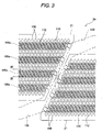
- Fig. 3 is an enlarged view of an area surrounded by an alternate long and short dash line in Fig. 2 .
- pressure chambers 110, apertures. 112 and nozzles 108 which are situated at lower portions in actuators 21 and, hence, should have been drawn by broken lines are drawn by solid lines.
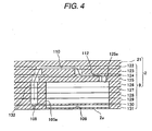
- Fig. 4 is a partial sectional view taken along the line IV-IV shown in Fig. 3 .
- the head main body 2 makes up the inkjet head 1 by a driver IC for generating drive signals for driving actuator units 21, and a reservoir unit which supplies some of ink from an ink tank to a flow path unit 9 while storing therein other ink being built therein.
- the head main body 2 in the head main body 2, four actuator units 21 are fixed to an upper surface 9a of the flow path unit 9.
- ink flow paths including manifold flow paths 105 and pressure chambers 110 are formed in an interior thereof.
- the actuator unit 21 includes a plurality of actuators which correspond to the pressure chambers 110 individually and functions to selectively give discharging energy to ink in the pressure chambers 110 by the actuators being driven by the.driver IC.
- the flow path unit 9 has a rectangular parallelepiped shape. 10 ink supply ports in total are opened in the upper surface 9a of the flow path unit 9 so as to correspond to ink outlet ports of the reservoir unit. As shown in Figs. 2 and 3 , two manifold flow paths 105 are formed in the interior of the flow path unit 9, each manifold flow path being made to communicate with the five ink supply ports 105b which are arranged in a longitudinal direction (a main scanning direction) of the flow path unit 9 in the vicinity of end portions with respect to a transverse direction (a sub-scanning direction) of the flow path unit 9.
- each manifold flow path 105 has a plurality of sub-manifold flow paths 105a which branch off so as to be parallel to each other and to extend in the main scanning direction.
- An ink discharge surface 2a is formed on a lower surface of the flow path unit 9, and a large number of nozzles 108 are disposed in a matrix fashion on the ink discharge surface 2a.
- the pressure chambers 110 are also arranged in a large number in a similar matrix fashion to that of the nozzles 108 in a surface to which the actuators 2-1 are fixed.
- 16 rows of pressure chambers 110 are arranged parallel to each other in the transverse direction of the flow path unit 9, each row including pressure chambers 110 aligned at equal intervals in the longitudinal direction of the flow path unit 9.
- the numbers of pressure chambers 110 in the respective pressure chamber rows correspond to an external shape (a trapezoidal shape) of the actuator unit 21, which will be described later, and the rows of pressure chambers are arranged such that the numbers of pressure chambers in the rows decrease gradually from a longer side toward a shorter side of the trapezoidal shape.
- the nozzles 108 are also arranged in a similar way.
- damper chambers 109 are formed so as to confront the sub-manifold flow path 105a.
- the damper chamber 9 is a space which is defined or held by a damper plate 130 and a nozzle plate 131, and here, the damper chamber 9 is defined by a recessed portion which is made to open to an upper surface of the nozzle plate 131 and a lower surface of the damper plate 130.
- the damper plate 130 being elastically deformed in the damper chamber 109, a pressure fluctuation in the sub-manifold flow path 105a is suppressed.
- the nozzles 108 from which ink droplets are discharged are formed in the nozzle plate 131, and the damper plate 130 configures a bottom wall of the sub-manifold flow path 105a.
- the flow path unit 9 includes 10 plates 122 to 131 which are made of a metallic material such as a stainless steel.
- the plates 122 to 131 (including a supply plate 125, manifold plates 126 to 129, a damper plate 130 and a nozzle plate 131) each have a rectangular flat surface which is elongated in the main scanning direction.
- Ink that is supplied from the reservoir unit into the flow path unit 9 via the ink supply ports 105b divides into the sub-manifold paths 105a in the manifold flow paths 105.
- Ink in the sub-manifold flow path 105a flows into the individual ink flow paths 132 and reaches the nozzles 108 via apertures 112 which function as diaphragms and the pressure chambers 110.
- Fig. 5 is a plan view of the four manifold plates 126 to 129 which form side walls of the manifold flow paths 105.
- Fig. 6 is a plan view of the manifold flow paths 105.
- Fig. 7 is a sectional view in relation to the line VII-VII shown in Fig. 6 .
- the supply plate 125, the damper plate 130 and the nozzle plate 131 which are not drawn in Fig. 6 are drawn. As is shown in Fig.
- the manifold flow paths 105 are formed by the supply plate 125, the four manifold plates 126 to 129 and the damper plate 130 being stacked together sequentially.
- the supply plate 125 configures a ceiling wall of the manifold flow paths 105, and the supply ports 125a are formed which configure one end portions of the individual ink flow paths 132.
- the respective manifold plates 126 to 129 configure the side walls of the manifold flow paths 105.
- the damper plate 130 configures the bottom wall of the manifold flow paths 105.
- the manifold plates 126 to 129 each have a plurality of island-like partial plates 126a, 127a, 128a, 129a which are surrounded by the manifold flow paths 105 (the sub-manifold paths 105a) and which extend in one direction (in a direction in which the sub-manifold paths 105a extend).
- parts of side walls of the sub-manifold flow paths 105a are configured by the partial plates 126a, 127a, 128a, 129a.
- support pieces 126b, 127b, 128b, 129b are formed, respectively, on the manifold plates 126 to 129 so as to cross the sub-manifold flow paths 105s and to support the corresponding partial plates 126a, 127a, 128a, 129a.
- an upper surface (a surface closer to the supply plate 125) of the support piece 126b, a lower surface (a surface closer to the damper plate 130) of the support piece 127b, an upper surface of the support piece 128b and a lower surface of the support piece 129b are all formed through half-etching.
- the upper surface of the support piece 126b is positioned lower than an upper surface of the partial plate 126a
- the lower surface of the support piece 127b is positioned upper than a lower surface of the partial plate 127a
- the upper surface of the support piece 128b is positioned lower than an upper surface of the partial plate 128a
- the lower surface of the support piece 129b is positioned upper than a lower surface of the partial plate 129a
- the thickness of the support pieces 126b, 127b, 128b, 129b is substantially half the thickness of the partial plates 126a, 127a, 128a, 129a, which smoothes the flow of ink and bubbles in the sub-manifold flow paths 105a.
- the support piece 126b since the upper surface of the support piece 126b is spaced apart from a lower surface of the supply plate 125, the support piece does not interrupt the flow of ink reaching the individual ink flow path 132 from the outlet port 125a formed in the supply port 125. Further, since the lower surface of the support piece 129b is spaced apart from an upper surface of the damper plate 130, the support piece 129b does not interrupt the movement of the damper plate 130.
- the support pieces 127b, 128b are further described.
- the support pieces 127b, 128b are formed, respectively, on the manifold plates 127, 128 which lie closest to the center of the sub-manifold flow paths 105a.
- the surface of the support piece 127b which lie closer to the center of the sub-manifold flow paths 105a is spaced farther from the center of the sub-manifold flow paths 105a than the central side surface of the manifold plate 127.
- the central side surface of the support pieces 128b is spaced farther from the center of the sub-manifold flow paths 105a than the central side surface of the support piece 128b.
- the four support pieces 126b, 127b, 128b, 129b are arranged at predetermined intervals in the direction in which the sub-manifold flow paths extend in the vicinity of each end portion of each sub-manifold flow path 105a in the sub-manifold flow path extending direction. In this way, the adjacent support pieces 126b, 127b, 128b, 129 are spaced apart from each other in the direction in which ink flows.
- one or two manifold plates of the four manifold plates 126 to 129 are interposed between the manifold plate 126 to 129 on which the support pieces 126b, 127b, 128b, 129b are formed and the different manifold plate 126 to 129 on which the support pieces 126b, 127b, 128b, 129b are formed which lie adjacent to the support pieces 126b, 127b, 128b, 129b in the direction in which the sub-manifold flow path 105a extends.
- the different manifold plate or plates are interposed between any two manifold plates which have the support pieces which lie adjacent to each other. Because of this, irrespective of the space in the flow path extending direction between the support pieces, bubbles are made to difficult to stay between the adjacent support pieces.
- the support piece 128b, the support piece 126b, the support piece 129b, the support piece 127b are arranged sequentially from a right-hand side of Fig. 7 in the direction in which the sub-manifold flow path 105a extends.
- the single manifold plate 127 is interposed between the manifold plate 128 on which the support piece 128b is formed and the manifold plate 126 on which the support piece 126b is formed.
- the two manifold plates 127, 128 are interposed between the manifold plate 126 on which the support piece 126b is formed and the manifold plate 129 on which the support piece 129b is formed.
- the single manifold plate 128 is interposed between the manifold plate 129 on which the support piece 129b is formed and the manifold plate 127 on which the support piece 127b is formed.
- the distances between the support pieces 126b, 127b, 128b, 129b which lie adjacent to one another in the extending direction of the sub-manifold flow path 105a are equal to or larger than the thickness of the respective manifold plates 126 to 129.
- the four support pieces 126b, 127b, 128b, 129b are disposed alternately along the extending direction of the sub-manifold flow path 105a so as to be closer either to the supply plate 125 side or to the damper plate 130 side than the center with respect to the stacking direction of the sub-manifold flow path 105a.
- a relationship in magnitude between a distance between one surfaces of the support pieces 126b, 127b, 128b, 129b and a wall of the sub-manifold flow path 105a which confronts the one surfaces and a distance between the other surfaces of the support pieces 126b, 127b, 128b, 129b and a wall of the sub-manifold flow path 105a which confronts the other surfaces is different from the same relationship in magnitude between the support pieces 126b, 127b, 128b, 129b and the other support pieces 126b, 127b, 128b, 129b which are adjacent thereto in the extending direction of the sub-manifold flow path 105a.
- the distances between the support pieces 126b, 127b, 128b, 129b which lie adjacent in the extending direction of the sub-manifold flow path 105a are equal to or larger than the thickness of the support pieces 126b, 127b, 128b, 129b, the staying of bubbles between the support pieces 126b, 127b, 128b, 129b which lie adjacent in the way described above can be suppressed, thereby making it possible to discharge bubbles that have flowed into the sub-manifold flow path 105a therefrom with good efficiency.
- the relationship in magnitude of the flow velocity in relation to the sides of the respective support pieces 126b, 127b, 128b, 129b with respect to the stacking direction switches along the extending direction for each of upon the support pieces 126b, 127b, 128b, 129b. Because of this, bubbles move while switching their rotating direction every time the bubbles pass by the support pieces 126b, 127b, 128b, 129b. By this action, the staying of bubbles between the adjacent support pieces 126b, 127b, 128b, 129b can be suppressed further.
- the support piece 126b since the upper surface of the support piece 126b is spaced apart from the supply plate 125, the support piece 126b does not interrupt the flow of ink reaching the individual ink flow path 132 from the supply port 125a formed in the supply plate 125. Because of this, ink and bubbles within the sub-manifold flow path 105a can be caused to flow into the individual ink flow path 132 with good efficiency.
- the support piece 129b since the lower surface of the support piece 129b is spaced apart from the damper plate 130, the support piece 129b does not interrupt the movement of the damper plate 130. Because of this, the damper chamber 109 can suppress pressure fluctuation that would take place in the sub-manifold flow path 105a.
- the surfaces of the support pieces 127b, 128b which face the stacking direction are spaced farther apart from the center than, of the two surfaces of the manifold plates 127, 128 on which the support pieces 127b, 128b are formed which are oriented in the stacking direction, the surfaces which lie closer to the center.
- the thickness of the support pieces 126b, 127b, 128b, 129b is substantially half the thickness of the respective partial plates 126a, 127a, 128b, 129a, the flow of ink and bubbles in the sub-manifold flow path 105a becomes smooth.
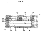
- the damper chamber 109 is formed by the damper plate 130 which lies adjacent to the manifold plate 129 and has a thin plate shape and the recessed portion of the nozzle plate 131 which has also a thin plate shape, the recessed portion being made to open to the upper surface of the nozzle plate 131.
- a nozzle plate 231 which has a thin plate shape may be made to lie adjacent to the manifold plate 129.
- the nozzle plate 231 doubles as a damper plate to elastically be deformed, whereby pressure fluctuation in the sub-manifold flow path 105a can be suppressed.
- the invention is not such as to be limited to the exemplary embodiment that has been described above but can be modified variously without departing from the scope of the claims of the invention.
- the four manifold plates 126 to 129 are made to form the side walls of the manifold flow paths 105
- a configuration may be adopted in which five manifold plates configure the side walls of the manifold flow paths 105.
- one or a plurality of other manifold plates of the five manifold plates are interposed between the manifold plate on which the support piece is formed and the different manifold plate on which the support piece is formed which lies adjacent thereto in the extending direction of the manifold flow path 105a.
- the upper surface of the support piece 126b may be in contact with the supply plate 125 in areas where the supply ports 125a are not opened.
- the lower surface of the support piece 129b is made to be spaced apart from the bottom wall (the damper plate 130) of the sub-manifold flow path 105a, the lower surface of the support piece may be in contact with the bottom wall.
- the bottom wall preferably does not have the damper function.
- the other surfaces of the respective support pieces may be positioned upper or lower than the surfaces of the corresponding martial plates 126a, 127a, 128a, 129a.
- the sides of at least any of the support pieces may be positioned in the same position as the surfaces of the corresponding partial plate 126a.
- such a support piece is preferably formed on the partial plate which lies closer to the center of the sub-manifold flow path 105a.
- the adjacent support pieces 126b, 127b, 128b, 129b are spaced apart from one another in the ink flowing direction
- the adjacent support pieces may lie adjacent to one another in the ink flowing direction, or at least part of the adjacent support pieces may be overlapped.
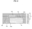
- the damper chamber 109 may be formed on the ceiling wall side of the sub-manifold flow path 105a.
- a damper chamber 209 is formed so as to confront a sub-manifold flow path 105a.
- a supply plate 225 has a double plate configuration in which it is made up of a lower plate 225b and an upper plate 225c. Of these constituent plates, the lower plate 225b is thinnest compared with the other plates and doubles as a damper plate.
- the damper chamber 209 configures a space held by the lower plate 225b and the upper plate 225c and is defined by a recessed portion formed on a lower surface of the upper plate 225c and an upper surface of the lower plate 225b.
- the supply plate 225 has a through port 225a which is formed so as to penetrate through the lower plate 225b and the upper plate 225c, and the recessed portion on the upper plate 225c is formed over an overall width of the sub-manifold flow path 105a while avoiding the supply port 225a.
- the lower plate 225b configures a ceiling wall of the sub-manifold flow path 105a.
- an upper surface of a support piece 126b on a manifold plate 126 is preferably spaced apart from the lower surface of the lower plate 225b.
- the flow path unit may have no damper chamber.
- a liquid discharging head including a flow path unit in which a plurality of common liquid flow paths and a plurality of individual ink flow paths which reach nozzles from outlets of the common liquid flow paths are formed by stacking a plurality of plates, wherein at least parts of side walls of the common liquid flow paths are configured by walls of island-like partial plates which are surrounded by the common liquid flow paths, wherein support pieces are formed on four or more manifold plates of the plurality of plates which configure the walls of the common flow paths in such a manner as to cross the common liquid flow paths and to support the walls of the partial plates, and wherein one or a plurality of manifold plates of the four or more manifold plates are disposed between the manifold plate on which the support piece is formed and the different manifold plate on which the support piece is formed which lies adjacent to the support piece in a direction in which the common liquid flow paths extend.
- the staying of bubbles between the adjacent support pieces can be suppressed.
- bubbles that have flowed into the common liquid flow paths can be discharged with good efficiency.
- a relationship in magnitude between a distance between one surface of the support piece and a wall surface of the common liquid flow path which confronts the one surface and a distance between the other surface of the support piece and a wall surface of the common liquid flow path which confronts the other surface is preferably different from the same relationship in magnitude between the support piece and the support piece which lies adjacent to the support piece in the common liquid flow path extending direction, with respect to a stacking direction of the four or more manifold plates.
- the relationship in magnitude of flow velocity between the sides of each support piece with respect to the stacking direction changes from support piece to support piece along the extending direction. Because of this, every time bubbles pass by the support piece, the bubbles move or flow while switching the rotating direction thereof. This can suppress further the staying of bubbles between the adjacent support pieces.
- the outlets are preferably formed in a supply plate which becomes a ceiling wall of the common liquid flow paths, and the support pieces formed on the manifold plate which is adjacent to the supply plate are preferably spaced apart from the supply plate.
- the flow path unit may become a bottom wall of the common liquid flow paths and have a nozzle plate in which the nozzles are formed, and the support pieces formed on the manifold plate which lies adjacent to the nozzle plate may be spaced apart from the nozzle plate.
- the flow path unit may have a damper plate which becomes a bottom wall of the common liquid flow paths, and a nozzle plate in which the nozzles are formed and which forms with the damper plate a damper chamber which confronts the common liquid flow paths via the damper plate, and the support pieces formed on the manifold plate which lies adjacent to the damper plate may be space apart from the damper plate.
- a surface of the support piece which lies closer to a center of the common liquid flow paths is preferably spaced farther apart from the center than, of two faces of the manifold plate on which the support piece is formed which face the stacking direction, a surface which lies closer to the center.
- the thickness of the support pieces formed on all the manifold plates is preferably thinner than the thickness of partial plates. According to this configuration, since the thickness of the support pieces become thin, the flow of liquid and bubbles within the common liquid flow paths can be made smooth.
- the support pieces are preferably disposed spaced apart from the different support pieces which lie adjacent thereto in the common liquid flow path extending direction, with respect to the common liquid flow path extending direction. According to this configuration, since the adjacent support pieces are spaced apart from each other with respect to the direction in which liquid flows, the staying of bubbles between the adjacent support pieces can be suppressed.
- an ink-jet head including a flow path unit in which a common ink flow path, a plurality of branch ink flow paths which branch off from the common ink flow path, and a plurality of individual ink flow paths which reach nozzles from outlets of the branch ink flow paths via pressure chambers are formed by a plurality of metallic plates including four or more manifold plates being stacked together, wherein the common ink flow path, the branch ink flow paths, island-like partial plates which are surrounded along the full circumference thereof by the branch ink flow paths and support pieces which are disposed in such a manner as to cross the branch ink flow paths and to support the partial plates by connecting together side walls of the branch ink flow paths which confront each other across the branch ink flow paths are formed in the four or more manifold plates, and wherein one or a plurality of manifold plates of the four or more manifold plates are disposed, with respect to the stacking direction, between the manifold plate on which the support pieces
Landscapes
- Particle Formation And Scattering Control In Inkjet Printers (AREA)
- Ink Jet (AREA)
- Coating Apparatus (AREA)
Claims (9)
- Tête de décharge de liquide (1) comprenant :une unité de trajectoire d'écoulement (9) comprenant :dans laquelle :une trajectoire d'écoulement de liquide commune (105, 105a) ;une trajectoire d'écoulement de liquide individuelle (132) qui atteint une buse (108) à partir d'une sortie de la trajectoire d'écoulement de liquide commune ; etune pluralité de plaques (122 à 131) qui sont empilées afin de former la trajectoire d'écoulement de liquide commune (105a) et la trajectoire d'écoulement de liquide individuelle (132), la pluralité de plaques comprenant au moins quatre plaques de collecteur (126 à 129) qui comprennent des plaques partielles et des éléments de support (126a à 129b),chacune des au moins quatre plaques de collecteur (126 à 129) comprend :dans laquelle :une plaque respective des plaques partielles (126a à 129a), qui a une forme d'île, et qui est entourée par la trajectoire d'écoulement de liquide commune ; etun élément respectif des éléments de support (126b à 129b) qui raccorde les parois des plaques partielles aux parois latérales de la trajectoire d'écoulement de liquide commune afin de croiser la trajectoire d'écoulement de liquide commune, les parois latérales de la trajectoire d'écoulement de liquide commune comprenant les parois des plaques partielles, etles au moins quatre plaques de collecteur comprennent :une première plaque de collecteur (126) qui comprend une première plaque partielle (126a) et un premier élément de support (126b) qui supporte la première plaque partielle (126a) ;une deuxième plaque de collecteur (128) qui comprend une deuxième plaque partielle (128a) et un deuxième élément de support (128b) qui est adjacent au premier élément de support (126b) dans une direction dans laquelle la trajectoire de liquide commune (105a) s'étend, le deuxième élément de support (128b) supportant la deuxième plaque partielle (128a) ; etau moins une plaque de collecteur (127) qui est intercalée entre la première plaque de collecteur (126) et la deuxième plaque de collecteur (128).
- Tête de décharge de liquide (1) selon la revendication 1, dans laquelle :une première relation de grandeur entre une distance entre une surface du premier élément de support (126b) et une surface de paroi de la trajectoire d'écoulement de liquide commune (105a) qui fait face à la première surface du premier élément de support (126b) et une distance entre une autre surface du premier élément de support (126b) et une surface de paroi de la trajectoire d'écoulement de liquide commune (105a) qui fait face à l'autre surface du premier élément de support (126b) est différente d'une deuxième relation de grandeur entre une distance entre une surface du deuxième élément de support (128b) et une surface de paroi de la trajectoire d'écoulement de liquide commune (105a) qui fait face à la première surface du deuxième élément de support (128b) et une distance entre une autre surface du deuxième élément de support (128b) et une surface de paroi de la trajectoire d'écoulement de liquide commune (105a) qui fait face à l'autre surface du deuxième élément de support (128b) dans une direction d'empilement dans laquelle les au moins quatre plaques de collecteur s'empilent.
- Tête de décharge de liquide (1) selon la revendication 1, dans laquelle :la pluralité de plaques comprend en outre une plaque d'alimentation (125) qui est une paroi de plafond de la trajectoire d'écoulement de liquide commune (105a), la plaque d'alimentation (125) comprenant les sorties (125a) de la trajectoire d'écoulement de liquide commune (105a), et dans laquelle :l'élément de support (126b), qui est formé sur la plaque de collecteur (126) qui est adjacente à la plaque d'alimentation (125), est espacé de la plaque d'alimentation.
- Tête de décharge de liquide (1) selon la revendication 1, dans laquelle :la pluralité de plaques comprend en outre une plaque de buse (131) qui est une paroi inférieure de la trajectoire d'écoulement de liquide commune (105a), la plaque de buse (131) comprenant la buse (108) de l'unité de trajectoire d'écoulement, etdans laquelle :l'élément de support (129b), qui est formé sur la plaque de collecteur (129) qui est adjacente à la plaque de buse (131), est espacé de la plaque de buse (131).
- Tête de décharge de liquide (1) selon la revendication 1, dans laquelle la pluralité de plaques comprend en outre :une plaque d'amortisseur (130) en tant que paroi inférieure de la trajectoire d'écoulement de liquide commune (105a) ; etune plaque de buse (131) comprenant la buse (108) de l'unité de trajectoire d'écoulement,dans laquelle :une chambre d'amortisseur (109) est formée par la plaque d'amortisseur (130) et la plaque de buse (131), la chambre d'amortisseur (109) faisant face à la trajectoire d'écoulement de liquide commune sur la plaque d'amortisseur (130), etl'élément de support (129b), qui est formé sur la plaque de collecteur (129) qui est adjacente à la plaque d'amortisseur (130), est espacé de la plaque d'amortisseur (130).
- Tête de décharge de liquide (1) selon la revendication 1, dans laquelle :parmi les deux surfaces de l'élément de support (129b), observées à partir de la direction d'empilement, une surface de l'élément de support qui est plus à proximité d'un centre de la trajectoire d'écoulement de liquide commune (105a) est plus éloignée du centre que, parmi les deux faces de la plaque de collecteur sur laquelle l'élément de support est formé, comme observé à partir de la direction d'empilement, une face de la plaque de collecteur qui est plus près du centre.
- Tête de décharge de liquide (1) selon la revendication 1, dans laquelle une épaisseur des éléments de support (126b à 129b) formée sur la totalité des plaques de collecteur (126 à 129) est plus fine qu'une épaisseur des plaques partielles (126a à 129a).
- Tête de décharge de liquide (1) selon la revendication 1, dans laquelle le premier élément de support (126b) est disposé à distance du deuxième élément de support (128b) qui est adjacent au premier élément de support dans la direction dans laquelle la trajectoire de liquide commune s'étend.
- Tête de jet d'encre (1) comprenant :une unité de trajectoire d'écoulement (9) comprenant :une trajectoire d'écoulement d'encre commune (105) ;une pluralité de trajectoires d'écoulement d'encre de ramification qui se ramifient à partir de la trajectoire d'écoulement d'encre commune (105a) ;une pluralité de trajectoires d'écoulement d'encre individuelles (132) qui atteignent des buses (108) à partir des sorties des trajectoires d'écoulement d'encre de ramification par le biais des chambres de pression (110) ; etune pluralité de plaques métalliques (122 à 131) qui sont empilées afin de former la trajectoire d'écoulement de liquide commune, les trajectoires d'écoulement d'encre de ramification et les trajectoires d'écoulement d'encre de liquide individuelles, la pluralité de plaques métalliques comprenant au moins quatre plaques de collecteur (126 à 129) qui comprennent la trajectoire d'écoulement de liquide commune, les trajectoires d'écoulement d'encre de ramification, les plaques partielles (126a à 129a) et les éléments de support (126b à 129b), dans laquelle :chacune des au moins quatre plaques de collecteur (126 à 129) comprend :une plaque respective des plaques partielles (126a à 129a), qui a une forme d'île, et qui est entourée par une trajectoire respective des trajectoires d'écoulement d'encre de ramification (105a) ; etun élément respectif des éléments de support (126b à 129b) qui raccorde les parois latérales de la trajectoire d'écoulement d'encre de ramification respective afin de supporter la plaque partielle respective et croiser la trajectoire d'écoulement de liquide commune, etdans laquelle les au moins quatre plaques de collecteur comprennent :une première plaque de collecteur (126) qui comprend une première plaque partielle (126a) et un premier élément de support (126b) qui supporte la première plaque partielle ; etune deuxième plaque de collecteur (128) qui comprend une deuxième plaque partielle (128a) et un deuxième élément de support (128b) qui est adjacent au premier élément de support dans une direction dans laquelle les trajectoires d'écoulement d'encre de ramification s'étendent, le deuxième élément de support supportant la deuxième plaque partielle ; etau moins une plaque de collecteur (127) qui est intercalée entre la première plaque de collecteur et la deuxième plaque de collecteur.
Applications Claiming Priority (1)
| Application Number | Priority Date | Filing Date | Title |
|---|---|---|---|
| JP2008084268A JP4582171B2 (ja) | 2008-03-27 | 2008-03-27 | 液滴吐出ヘッド及びインクジェットヘッド |
Publications (2)
| Publication Number | Publication Date |
|---|---|
| EP2105302A1 EP2105302A1 (fr) | 2009-09-30 |
| EP2105302B1 true EP2105302B1 (fr) | 2011-05-11 |
Family
ID=40740471
Family Applications (1)
| Application Number | Title | Priority Date | Filing Date |
|---|---|---|---|
| EP09004396A Active EP2105302B1 (fr) | 2008-03-27 | 2009-03-26 | Tête à décharge de liquide et tête à jet d'encre |
Country Status (4)
| Country | Link |
|---|---|
| US (1) | US8016390B2 (fr) |
| EP (1) | EP2105302B1 (fr) |
| JP (1) | JP4582171B2 (fr) |
| CN (1) | CN101544115B (fr) |
Families Citing this family (7)
| Publication number | Priority date | Publication date | Assignee | Title |
|---|---|---|---|---|
| CN103608182B (zh) * | 2011-06-28 | 2016-03-30 | 京瓷株式会社 | 液体喷出头以及使用该液体喷出头的记录装置 |
| US9168747B2 (en) * | 2013-10-08 | 2015-10-27 | Xerox Corporation | Multi-layer electroformed nozzle plate with attenuation pockets |
| US10022957B2 (en) | 2015-04-24 | 2018-07-17 | Fujifilm Dimatrix, Inc. | Fluid ejection devices with reduced crosstalk |
| US10471717B2 (en) | 2015-11-11 | 2019-11-12 | Kyocera Corporation | Liquid ejection head, recording device, and method manufacturing liquid ejection head |
| US10611144B2 (en) * | 2017-06-09 | 2020-04-07 | Fujifilm Dimatix, Inc. | Fluid ejection devices with reduced crosstalk |
| JP6905786B2 (ja) * | 2017-09-28 | 2021-07-21 | 京セラ株式会社 | 流路部材、液体吐出ヘッドおよび記録装置 |
| ES2900821B2 (es) * | 2020-09-18 | 2023-01-09 | Gruppo Tecnoferrari Spa | Sistema de alimentación de cabezales de impresión por chorro de tinta y aparato de impresión correspondiente |
Family Cites Families (12)
| Publication number | Priority date | Publication date | Assignee | Title |
|---|---|---|---|---|
| JP4748833B2 (ja) * | 2000-06-22 | 2011-08-17 | パナソニック株式会社 | インクジェットヘッド及びインクジェット式記録装置 |
| US6862806B2 (en) * | 2000-10-17 | 2005-03-08 | Brother Kogyo Kabushiki Kaisha | Method for fabricating an ink-jet printer head |
| US6629870B2 (en) * | 2001-03-14 | 2003-10-07 | Little Kids, Inc. | Bubble blower |
| JP3876805B2 (ja) * | 2002-09-26 | 2007-02-07 | ブラザー工業株式会社 | インクジェットヘッド |
| JP2004114477A (ja) * | 2002-09-26 | 2004-04-15 | Brother Ind Ltd | インクジェットヘッド |
| US7311380B2 (en) * | 2002-09-26 | 2007-12-25 | Brother Kogyo Kabushiki Kaisha | Inkjet head |
| JP4124055B2 (ja) * | 2003-08-11 | 2008-07-23 | ブラザー工業株式会社 | インクジェットヘッド及びインクジェットプリンタ |
| JP4274084B2 (ja) * | 2004-08-27 | 2009-06-03 | ブラザー工業株式会社 | インクジェットヘッド |
| JP4274085B2 (ja) * | 2004-08-27 | 2009-06-03 | ブラザー工業株式会社 | インクジェットヘッド |
| JP4306605B2 (ja) * | 2004-12-22 | 2009-08-05 | ブラザー工業株式会社 | インクジェットヘッドの製造方法 |
| JP2006198903A (ja) * | 2005-01-20 | 2006-08-03 | Brother Ind Ltd | インクジェットヘッド |
| JP2008084268A (ja) | 2006-09-29 | 2008-04-10 | Fujifilm Corp | スクラップ・ブック・サーバならびにその制御方法およびその制御プログラム |
-
2008
- 2008-03-27 JP JP2008084268A patent/JP4582171B2/ja active Active
-
2009
- 2009-03-26 EP EP09004396A patent/EP2105302B1/fr active Active
- 2009-03-27 CN CN2009101279393A patent/CN101544115B/zh active Active
- 2009-03-27 US US12/413,433 patent/US8016390B2/en active Active
Also Published As
| Publication number | Publication date |
|---|---|
| JP2009234096A (ja) | 2009-10-15 |
| US8016390B2 (en) | 2011-09-13 |
| JP4582171B2 (ja) | 2010-11-17 |
| CN101544115B (zh) | 2011-01-26 |
| CN101544115A (zh) | 2009-09-30 |
| EP2105302A1 (fr) | 2009-09-30 |
| US20090244199A1 (en) | 2009-10-01 |
Similar Documents
| Publication | Publication Date | Title |
|---|---|---|
| EP2105302B1 (fr) | Tête à décharge de liquide et tête à jet d'encre | |
| EP3459742B1 (fr) | Appareil d'injection liquide | |
| US8205978B2 (en) | Liquid ejecting head for effectively discharging air bubbles | |
| JP2012006224A (ja) | 液滴噴射装置 | |
| US8061821B2 (en) | Liquid-Droplet ejection head and ink jet printer | |
| JP7255297B2 (ja) | 液体吐出ヘッド | |
| JP4432925B2 (ja) | インクジェットヘッド | |
| JP2012200918A (ja) | 液体吐出ヘッド | |
| US11273644B2 (en) | Liquid discharge head | |
| JP4898122B2 (ja) | ドロップ放出装置 | |
| US7597426B2 (en) | Ink-jet head and ink-jet printer | |
| JP4557027B2 (ja) | 記録装置 | |
| US7222937B2 (en) | Drop generating apparatus | |
| US20070153065A1 (en) | Inkjet jet stack external manifold | |
| JP5434793B2 (ja) | 液滴噴射装置 | |
| US7815284B2 (en) | Liquid drop ejection head | |
| US6969146B2 (en) | Drop generating apparatus | |
| US8556380B2 (en) | Liquid discharge apparatus | |
| US20240316924A1 (en) | Liquid ejecting head | |
| US20050151785A1 (en) | Drop generating apparatus | |
| JP2011240630A (ja) | 液体吐出ヘッド | |
| JP5626070B2 (ja) | 液体吐出ヘッド | |
| US20050151784A1 (en) | Drop generating apparatus | |
| US20050151787A1 (en) | Drop generating apparatus | |
| JP2012213884A (ja) | 液体吐出ヘッド |
Legal Events
| Date | Code | Title | Description |
|---|---|---|---|
| PUAI | Public reference made under article 153(3) epc to a published international application that has entered the european phase |
Free format text: ORIGINAL CODE: 0009012 |
|
| AK | Designated contracting states |
Kind code of ref document: A1 Designated state(s): AT BE BG CH CY CZ DE DK EE ES FI FR GB GR HR HU IE IS IT LI LT LU LV MC MK MT NL NO PL PT RO SE SI SK TR |
|
| AX | Request for extension of the european patent |
Extension state: AL BA RS |
|
| 17P | Request for examination filed |
Effective date: 20100330 |
|
| AKX | Designation fees paid |
Designated state(s): DE FR GB |
|
| GRAP | Despatch of communication of intention to grant a patent |
Free format text: ORIGINAL CODE: EPIDOSNIGR1 |
|
| GRAS | Grant fee paid |
Free format text: ORIGINAL CODE: EPIDOSNIGR3 |
|
| RIN1 | Information on inventor provided before grant (corrected) |
Inventor name: WATANABE, HIDETOSHI |
|
| GRAA | (expected) grant |
Free format text: ORIGINAL CODE: 0009210 |
|
| AK | Designated contracting states |
Kind code of ref document: B1 Designated state(s): DE FR GB |
|
| REG | Reference to a national code |
Ref country code: GB Ref legal event code: FG4D |
|
| REG | Reference to a national code |
Ref country code: DE Ref legal event code: R096 Ref document number: 602009001250 Country of ref document: DE Effective date: 20110622 |
|
| PLBE | No opposition filed within time limit |
Free format text: ORIGINAL CODE: 0009261 |
|
| STAA | Information on the status of an ep patent application or granted ep patent |
Free format text: STATUS: NO OPPOSITION FILED WITHIN TIME LIMIT |
|
| 26N | No opposition filed |
Effective date: 20120214 |
|
| REG | Reference to a national code |
Ref country code: DE Ref legal event code: R097 Ref document number: 602009001250 Country of ref document: DE Effective date: 20120214 |
|
| REG | Reference to a national code |
Ref country code: FR Ref legal event code: PLFP Year of fee payment: 8 |
|
| REG | Reference to a national code |
Ref country code: FR Ref legal event code: PLFP Year of fee payment: 9 |
|
| REG | Reference to a national code |
Ref country code: FR Ref legal event code: PLFP Year of fee payment: 10 |
|
| P01 | Opt-out of the competence of the unified patent court (upc) registered |
Effective date: 20230529 |
|
| PGFP | Annual fee paid to national office [announced via postgrant information from national office to epo] |
Ref country code: GB Payment date: 20260209 Year of fee payment: 18 |
|
| PGFP | Annual fee paid to national office [announced via postgrant information from national office to epo] |
Ref country code: DE Payment date: 20260128 Year of fee payment: 18 |
|
| PGFP | Annual fee paid to national office [announced via postgrant information from national office to epo] |
Ref country code: FR Payment date: 20260209 Year of fee payment: 18 |