EP2105332A1 - Sonnenblende mit Plastikspiegel - Google Patents
Sonnenblende mit Plastikspiegel Download PDFInfo
- Publication number
- EP2105332A1 EP2105332A1 EP08102897A EP08102897A EP2105332A1 EP 2105332 A1 EP2105332 A1 EP 2105332A1 EP 08102897 A EP08102897 A EP 08102897A EP 08102897 A EP08102897 A EP 08102897A EP 2105332 A1 EP2105332 A1 EP 2105332A1
- Authority
- EP
- European Patent Office
- Prior art keywords
- sun visor
- mirror
- plastic glass
- molded
- plastic
- Prior art date
- Legal status (The legal status is an assumption and is not a legal conclusion. Google has not performed a legal analysis and makes no representation as to the accuracy of the status listed.)
- Granted
Links
- 239000011521 glass Substances 0.000 claims abstract description 24
- 239000000463 material Substances 0.000 description 6
- 210000001331 nose Anatomy 0.000 description 5
- 230000003014 reinforcing effect Effects 0.000 description 5
- 238000006073 displacement reaction Methods 0.000 description 3
- 238000002347 injection Methods 0.000 description 2
- 239000007924 injection Substances 0.000 description 2
- 238000004519 manufacturing process Methods 0.000 description 2
- 229910052751 metal Inorganic materials 0.000 description 2
- 230000002787 reinforcement Effects 0.000 description 2
- 230000006641 stabilisation Effects 0.000 description 2
- 238000011105 stabilization Methods 0.000 description 2
- 208000027418 Wounds and injury Diseases 0.000 description 1
- 230000015572 biosynthetic process Effects 0.000 description 1
- 238000010276 construction Methods 0.000 description 1
- 230000006378 damage Effects 0.000 description 1
- 208000014674 injury Diseases 0.000 description 1
- 238000009434 installation Methods 0.000 description 1
- 239000010410 layer Substances 0.000 description 1
- 239000002184 metal Substances 0.000 description 1
- 238000000034 method Methods 0.000 description 1
- 239000011241 protective layer Substances 0.000 description 1
- 238000005507 spraying Methods 0.000 description 1
- 239000000758 substrate Substances 0.000 description 1
Images

Classifications
-
- B—PERFORMING OPERATIONS; TRANSPORTING
- B60—VEHICLES IN GENERAL
- B60J—WINDOWS, WINDSCREENS, NON-FIXED ROOFS, DOORS, OR SIMILAR DEVICES FOR VEHICLES; REMOVABLE EXTERNAL PROTECTIVE COVERINGS SPECIALLY ADAPTED FOR VEHICLES
- B60J3/00—Antiglare equipment associated with windows or windscreens; Sun visors for vehicles
- B60J3/02—Antiglare equipment associated with windows or windscreens; Sun visors for vehicles adjustable in position
- B60J3/0204—Sun visors
- B60J3/0278—Sun visors structure of the body
- B60J3/0282—Sun visors structure of the body specially adapted for a courtesy mirror
Definitions
- the invention relates to a sun visor for vehicles, with a mirror which is recessed in a recess of the sun visor body, and a manually operable mirror cover.
- the mirror consists of a plastic glass with integrated guide elements.
- the cover of the mirror is, for example, an existing plastic slide, which has on the side facing away from the mirror a handle and engages with its running in the direction of displacement edges in a respective groove-like guide.
- the slider In the currently used sun visors with a mirror cover in the form of a slider, the slider is guided with its running in the direction of displacement edges in U-shaped of the V-shaped guides.
- the U-shaped guides cause a three-sided surface contact in the upper and lower guide portion of the slide, which makes it difficult to control the controllable and manageable slide in the guides.
- the parts, ie the slide and the guides are produced with a very large tolerance game to operate the slide even with larger temperature fluctuations can.
- this relatively large tolerance game often leads to complaints, as a result, the slide can move unintentionally and even - which is even less desirable - can develop into a rather unpleasant noise source by causing rattling noises.
- the invention provides a sun visor (1) with at least one integrated mirror surface in the sun visor body (2) to be provided, wherein the sun visor body (2) contains a receptacle for the mirror (15) and this mirror (15) Carrier made of plastic glass on the guide elements (17) for means for hiding the at least one mirror in the sun visor body (2) are molded directly.
- plastic glass considerably simplifies the construction of the sun visor and reduces the problem of the different thermal expansions of different materials. The risk of injury to a broken glass mirror in the sun visor is eliminated and the material plastic glass allows new designs and design options.
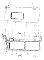
- Fig. 1 represents a complete sun visor 1, consisting of a sheathed sun visor body 2 with a counter-bearing pin 3, a mounted Anschraubaggregat 4 and an integrated in the sun visor body 2 mirror system.
- the first embodiment shows a sun visor with a slider which is arranged movably over a mirror. To use the mirror, it is moved slider on its handle bar to the right and the hidden mirror is visible.
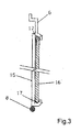
- Fig. 2 shows a prepared mainly from plastic injection reinforcement insert 6, which has a U-shaped wire stabilization 8 to avoid twisting in the outer region 7, which is fixed to Einklipsstellen 9.
- abutment pin 3 is reinforced with a wire bracket 11 by plug-in assembly to meet the crash requirements.
- the reinforcing insert 6 has an axle receiving portion 12 for the axis 13 of the Anschraubaggregats 4 and a detent spring 14 for the sliding / cogging torque. Since the reinforcing insert 6 is intended primarily for a diaphragm body half-shell system, the mirror 15 is preassembled with the slider 16 in accordance with section AA as well as the screw-4.
- the mirror is injected from plastic material with high precision.
- a method for producing plastic glass is used in the EP 1412158 A1 describe. The method allows a high dimensional stability as required by a mirror carrier. The plastic glass carrier will continue after demolding Subjected to steps. The mirror layer is applied to the substrate and protected by a protective layer.
- the upper and lower V-like guide 17 for the slider 16 extends almost over the entire length of the reinforcing insert 6. This guide 17 is injected directly when spraying the plastic glass with and consists of the same material.
- the slider 16 is a plastic injection molded part with approximately rectangular shape with a handle bar 18 and the formation of an upper and lower V-like or vice versa V-shaped edge.
- the top and bottom V-like edge on the slider 16 and the upper and lower V-like guide 17 of the mirror 15 cause by their combination, the dimensionally accurate vote on the one hand an optimal sliding / sliding action and on the other a rattle and play-free pairing due the special shape of the sliding and guiding zones.
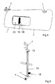
- Fig. 4 shows a further embodiment of the sun visor according to the invention.
- the sun visor body 1 has a recess 20 which is bounded by guides.
- the plastic mirror 15 is hidden in the rest position behind the sun visor body.
- a molded handle 18 on the mirror allows the user to pull the mirror to the right from a pocket-shaped receptacle of the sun visor body.
- the plastic glass mirror has to a reflective surface on a handle and molded guide elements in the form of lugs 19 which engage in the guides 17.
- the shape of the noses 19 can be as in FIG. 5 represented in the extension of the surface of the mirror lie or as in one embodiment Fig. 6 in a nose perpendicular to the mirror surface or by a kinked bridge.
- Fig. 7 shows a further embodiment with a cover flap 21, which is attached to a hinge 22.
- the flap is pivotally mounted.
- the plastic glass mirror 15 consists of the plane mirror surface with molded joint 22 and a molded-tub-like frame 24th
- the plastic glass fulfill several functions, namely the provision of a reflective surface and the guide element for hiding the mirror in the sun visor.
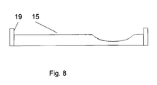
- FIG. 8 shows an embodiment with a planar and a curved mirror part. This form can be produced with plastic glass in one production step. In the figure, the noses are for recording in a guide 17 only indicated.
- the plastic glass has a flat back in this example, to simplify the installation in the sun visor.
Landscapes
- Engineering & Computer Science (AREA)
- Mechanical Engineering (AREA)
- Mirrors, Picture Frames, Photograph Stands, And Related Fastening Devices (AREA)
- Rear-View Mirror Devices That Are Mounted On The Exterior Of The Vehicle (AREA)
Abstract
Description
- Die Erfindung bezieht sich auf eine Sonnenblende für Fahrzeuge, mit einem Spiegel, der vertieft in einer Aussparung des Sonnenblendenkörpers liegt, und einer manuell betätigbaren Spiegelabdeckung. Der Spiegel besteht aus einen Plastikglas mit integrierten Führungselementen. Die Abdeckung des Spiegels ist dabei beispielsweise ein aus Kunststoff bestehender Schieber, der auf der dem Spiegel abgekehrten Seite eine Griffleiste aufweist und mit seinen in der Verschieberichtung verlaufenden Rändern in je eine nutartige Führung eingreift.
- Bei den zurzeit gebräuchlichen Sonnenblenden mit einer Spiegelabdeckung in Form eines Schiebers wird der Schieber mit seinen in der Verschieberichtung verlaufenden Rändern in U-förmigen der V-förmigen Führungen geführt. Die U-förmigen Führungen bewirken eine dreiseitige Flächenberührung im oberen und unteren Führungsbereich des Schiebers, die eine kontrollierbare und beherrschbare Gleitung des Schiebers in den Führungen erschwert. In der Regel werden die Teile, d.h. der Schieber und die Führungen mit einem masslich sehr großen Toleranzspiel produziert, um den Schieber auch noch bei größeren Temperaturschwankungen betätigen zu können. Dieses relativ große Toleranzspiel führt aber häufig zu Reklamationen, da sich hierdurch der Schieber ungewollt verschieben kann und auch - was noch weniger erwünscht ist - zu einer recht unangenehmen Geräuschquelle entwickeln kann, indem er Klappergeräusche verursacht. Um ein verbessertes Gleiten des Schiebers in den U-förmigen Führungen zu erreichen, wurden schon an den in der Verschieberichtung verlaufenden Rändern des Schiebers Metallfedern angeordnet, die aber nicht dazu führen konnten, die unangenehmen Klappergeräusche abzustellen. Eine weitere Verbesserung wurde mit der
DE 10164887 durch eine V-förmige Nut erreicht.
Zur Abdeckung von Spiegeln in Sonnenblenden sind auch Abdeckklappen bekannt. Beispielsweise wird in derDE4440606 eine Abdeckung beschrieben, die in einer angeformten Nase des Spiegelrahmens angebracht ist. - Das Problem der zuverlässigen Führung einer Abdeckung wie eines Schiebers, oder einer Abdeckklappe wird durch die Verwendung unterschiedlicher Materialien und deren unterschiedliche Wärmeausdehnung verschärft. Es ist daher die Aufgabe der Erfindung dieses Problem zu lösen und einen Sonnenblende vorzuschlagen, deren Materialen aus Kunststoff und wenigen metallischen Elementen besteht.
- Zur Lösung dieser Aufgabe ist erfindungsgemäß vorgesehen, eine Sonnenblende (1) mit mindestens einer integrierten Spiegelfläche im Sonnenblendenkörper (2) zur Verfügung zu stellen, wobei der Sonnenblendenkörper (2) eine Aufnahme für den Spiegel (15) enthält und dieser Spiegel (15) einen Träger aus Plastikglas aufweist, an dem Führungselemente (17) für Mittel zum Verbergen des mindestes einen Spiegel im Sonnenblendenkörper (2) direkt angespritzt sind.
Durch die Verwendung von Plastikglas wird der Aufbau der Sonnenblende wesentlich vereinfacht und das Problem der unterschiedlichen Wärmeausdehnungen von unterschiedlichen Materialien reduziert. Die Verletzungsgefahr an einem zerbrochenen Glasspiegel in der Sonnenblende entfällt und das Material Plastikglas ermöglich neue Designs und Gestaltungsmöglichkeiten.
Besonders vorteilhaft ist es, dass mit Plastikglas flache sowie jede Art von gewölbten Spiegel hergestellt werden können, sodass ohne Mehraufwand ein flacher Spiegel durch einen Spiegel mit flachen und konkaven Anteil ersetzt werden kann.
Durch die erfindungsgemäßen Maßnahmen wird in einfacher und kostengünstiger Weise eine wesentliche Qualitätsverbesserung erreicht. - Ein Ausführungsbeispiel der Erfindung wird im Folgenden anhand der Zeichnung näher erläutert, und es zeigen:
-
Fig. 1 eine Sonnenblende in Ansicht, -
Fig. 2 eine Verstärkungseinlage für die Sonnenblende nachFig. 1 , -
Fig. 3 einen Schnitt etwa folgend der Linie A-A inFig. 2 und -
Fig. 4 eine zweite Ausführungsform der Erfindung -
Fig 5 ein Schnitt durch die Ausführungsform nachFig. 4 -
Fig. 6 einen Schnitt mit alternativen Führungen -
Fig. 7 eine dritte Ausführungsform -
Fig. 8 einen Spiegelausführung. -
Fig. 1 stellt eine komplette Sonnenblende 1 dar, bestehend aus einem umhüllten Sonnenblendenkörper 2 mit einem Gegenlagerstift 3, einem montierten Anschraubaggregat 4 und einem im Sonnenblendenkörper 2 integriertem Spiegelsystem 5.
Das erste Ausführungsbeispiel zeigt eine Sonnenblende mit einem Schieber, der über einem Spiegel bewegbar angeordnet ist. Zur Benutzung des Spiegels wird er Schieber an seiner Griffleiste nach rechts bewegt und der verborgene Spiegel wird sichtbar. -
Fig. 2 zeigt eine im Wesentlich aus Kunststoffspritzguss erstellte Verstärkungseinlage 6, die zur Vermeidung von Verwindungen im äußeren Bereich 7 eine U-förmige Drahtstabilisierung 8 aufweist, die an Einklipsstellen 9 festgelegt ist. Im Gegenlagerbereich 10 ist der an der Verstärkungseinlage 6 angespritzte Gegenlagerstift 3 mit einem Drahtbügel 11 durch Steckmontage verstärkt, um die Crashforderungen zu erfüllen. Die Verstärkungseinlage 6 weist einen Achsaufnahmebereich 12 für die Achse 13 des Anschraubaggregats 4 auf sowie eine Rastfeder 14 für das Gleit-/Rastmoment. Da die Verstärkungseinlage 6 vornehmlich für ein Blendenkörperhalbschalensystem vorgesehen ist, ist der Spiegel 15 mit dem Schieber 16 entsprechend Schnitt A-A ebenso vormontiert wie das Anschraubaggregat 4.
Erfindungsgemäß wird der Spiegel aus Plastikmaterial mit hoher Präzision gespritzt. Ein verfahren zur Herstellung von Plastikglas wird in derEP 1412158 A1
beschreiben. Das Verfahren ermöglicht eine hohe Maßhaltigkeit wie sie von einem Spiegelträger gefordert ist. Der Plastikglasträger wird nach dem Entformen weiteren Schritten unterzogen. Die Spiegelschicht wird auf das Trägermaterial aufgebracht und von einer Schutzschicht geschützt. - Die obere und untere V-artige Führung 17 für den Schieber 16 erstreckt sich nahezu über die gesamte Länge der Verstärkungseinlage 6. Diese Führung 17 wird beim Spritzen des Plastikglases direkt mit angespritzt und besteht aus demselben Material.
Der Schieber 16 ist ein Kunststoffspritzteil mit etwa rechteckiger Form mit einer Griffleiste 18 und der Ausbildung einer oberen und unteren V-artigen oder umgekehrt V-förmigen Randkante.
Die obere und unter V-artige Randkante am Schieber 16 und die obere und untere V-artige Führung 17 des Spiegels 15 bewirken durch ihre Kombination, der maßgenaue Abstimmung zum einen eine optimale Schiebe-/Gleitwirkung und zum anderen eine klapper- und spielfreie Paarung aufgrund der besonderen Formgebung der Gleit- und Führungszonen. -
Fig 4 zeigt eine weitere Ausführungsform der erfindungsgemäßen Sonnenblende. Der Sonnenblendenkörper 1 weist eine Aussparung 20 auf, die von Führungen begrenzt ist. Der Plastikspiegel 15 ist in der Ruheposition hinter dem Sonneblendenkörper verborgen. Ein angespritzter Griff 18 auf dem Spiegel ermöglicht es dem Benutzer den Spiegel nach rechts aus einer taschenförmigen Aufnahme des Sonnenblendenkörpers zu ziehen. Der Plastikglasspiegel weist zu einer spiegelnden Fläche noch einen Griff sowie angespritzte Führungselemente in Form von Nasen 19 auf, die in die Führungen 17 eingreifen. Die Form der Nasen 19 kann wie inFigur 5 dargestellt in der Verlängerung der Fläche des Spiegels liegen oder wie in einer Ausführungsform nachFig. 6 in einer Nase senkrecht zur Spiegelfläche oder durch einen abknickenden Steg.
Für die Erfindung ist die Art der Führung nicht wesentlich. Jede Führungsform die einem Fachmann zur Verfügung steht ist zur Ausführung der Erfindung geeignet.
Fig. 7 zeigt einen weitere Ausführungsform mit einer Abdeckklappe 21, die an einem Gelenk 22 angebracht ist. Die Klappe ist schwenkbar gelagert. Der Plastikglasspiegel 15 besteht aus der planen Spiegelfläche mit angespritzten Gelenk 22 und einem angespritzten wannenartigen Rahmen 24. - Auch in dieser Ausführungsform ist es wichtig, dass das Plastikglas mehrere Funktionen erfüllt, nämlich die Bereitstellung einer spiegelnden Fläche und die Führungselement zum Verbergen des Spiegels in der Sonnenblende.
-
Figur 8 zeigt einen Ausführungsform mit einem planen und einem gewölbten Spiegelteil. Diese Form ist mit Plastikglas in einem Produktionsschritt herstellbar. In der Figur werden die Nasen zu Aufnahme in eine Führung 17 nur angedeutet. - Das Plastikglas weist in diesem Beispiel eine plane Rückseite auf, um das verbauen in der Sonnenblende zu vereinfachen.
-
- 1 Sonnenblende
- 2 Sonnenblendenkörper
- 3 Gegenlagerstift
- 4 Anschraubaggregat
- 5 Spiegelsystem
- 6 Verstärkungseinlage
- 7 äußerer Bereich
- 8 Drahtstabilisierung
- 9 Einklipsstelle
- 10 Gegenlagerbereich
- 11 Drahtbügel
- 12 Achsaufnahmebereich
- 13 Achse
- 14 Rastfeder
- 15 Spiegel
- 16 Schieber
- 17 Führung
- 18 Griffleiste
- 19 Nase
- 20 Aussparung
- 21 Abdeckklappe
- 22 Gelenk
- 23 Schalter
- 24 angespritzte Rahmen
Claims (9)
- Sonnenblende (1) mit mindestens einer integrierten Spiegelfläche im Sonnenblendenkörper (2), wobei der Sonnenblendenkörper (2) eine Aufnahme für den mindestens einen Spiegel (15) enthält, dadurch gekennzeichnet, dass der Spiegel (15) einen Träger aus Plastikglas aufweist, an dem Führungselemente (17) für Mittel zum Verbergen des mindestes einen Spiegel im Sonnenblendenkörper (2) direkt angespritzt sind.
- Sonnenblende (1) nach Anspruch 1 dadurch gekennzeichnet, dass an das Plastikglas Führungen in Form von Nuten angespritzt sind und der Spiegel (15) mit einem Schieber (16), der in den Nuten (17) läuft, abdeckbar ist.
- Sonnenblende (1) nach Anspruch 1 dadurch gekennzeichnet, dass an das Plastikglas Führungen in Form von Nasen angespritzt sind, die zur Aufnahme einer Abdeckklappe dienen.
- Sonnenblende (1) nach Anspruch 1 dadurch gekennzeichnet, dass an das Plastikglas Führungen in Form von Stegen angespritzt sind.
- Sonnenblende (1) nach Anspruch 1 dadurch gekennzeichnet, dass an das Plastikglas ein Griff angespritzt ist.
- Sonnenblende (1) nach Anspruch 1 dadurch gekennzeichnet, dass an das Plastikglas rückseitig mit einer reflektierenden Schicht bedampft ist.
- Sonnenblende (1) nach Anspruch 1 dadurch gekennzeichnet, dass an das Plastikglas vorderseitig mit einer reflektierenden Schicht bedampft ist.
- Sonnenblende (1) nach Anspruch 1 dadurch gekennzeichnet, dass das Plastikglas aus einem flachen und einem konkav geformten Teil besteht.
- Sonnenblende (1) nach Anspruch 1 dadurch gekennzeichnet, dass das Plastikglas einen angespritzten Griff (18) aufweist.
Priority Applications (3)
| Application Number | Priority Date | Filing Date | Title |
|---|---|---|---|
| EP08102897A EP2105332B1 (de) | 2008-03-25 | 2008-03-25 | Sonnenblende mit Plastikspiegel |
| DE502008000304T DE502008000304D1 (de) | 2008-03-25 | 2008-03-25 | Sonnenblende mit Plastikspiegel |
| US12/410,594 US8336943B2 (en) | 2008-03-25 | 2009-03-25 | Sun visor with plastic mirror |
Applications Claiming Priority (1)
| Application Number | Priority Date | Filing Date | Title |
|---|---|---|---|
| EP08102897A EP2105332B1 (de) | 2008-03-25 | 2008-03-25 | Sonnenblende mit Plastikspiegel |
Publications (2)
| Publication Number | Publication Date |
|---|---|
| EP2105332A1 true EP2105332A1 (de) | 2009-09-30 |
| EP2105332B1 EP2105332B1 (de) | 2010-01-06 |
Family
ID=39577737
Family Applications (1)
| Application Number | Title | Priority Date | Filing Date |
|---|---|---|---|
| EP08102897A Active EP2105332B1 (de) | 2008-03-25 | 2008-03-25 | Sonnenblende mit Plastikspiegel |
Country Status (3)
| Country | Link |
|---|---|
| US (1) | US8336943B2 (de) |
| EP (1) | EP2105332B1 (de) |
| DE (1) | DE502008000304D1 (de) |
Families Citing this family (3)
| Publication number | Priority date | Publication date | Assignee | Title |
|---|---|---|---|---|
| DE102004060758B4 (de) * | 2004-12-15 | 2013-08-01 | Johnson Controls Interiors Gmbh & Co. Kg | Spiegelmodul für eine Sonnenblende für ein Fahrzeug, Sonnenblende für ein Kraftfahrzeug |
| JP2012101623A (ja) * | 2010-11-09 | 2012-05-31 | Kyowa Sangyo Kk | ミラーユニット |
| JP6896572B2 (ja) * | 2017-09-01 | 2021-06-30 | 共和産業株式会社 | ミラーユニット |
Citations (8)
| Publication number | Priority date | Publication date | Assignee | Title |
|---|---|---|---|---|
| GB2009022A (en) * | 1977-11-07 | 1979-06-13 | Faure Bertrand Ind | Moulding a Sun Visor, comprising a Mirror |
| FR2431932A1 (fr) * | 1978-07-28 | 1980-02-22 | Maglum Sa | Procede de fabrication d'un ecran de pare-soleil de vehicule a moteur |
| EP0076174A1 (de) * | 1981-09-28 | 1983-04-06 | COMPAGNIE INDUSTRIELLE DE MECANISMES en abrégé C.I.M. Société dite: | Sonnenblende für Kraftfahrzeuge |
| DE4440606A1 (de) | 1994-11-14 | 1996-05-15 | Happich Gmbh Gebr | Sonnenblende für Fahrzeuge |
| US20030001301A1 (en) * | 2001-07-02 | 2003-01-02 | Bernard Duroux | Plastic glass |
| DE10153154A1 (de) * | 2001-10-27 | 2003-05-15 | Johnson Contr Interiors Gmbh | Sonnenblende für Fahrzeuge |
| DE10164887B4 (de) | 2001-10-27 | 2006-04-27 | Johnson Controls Interiors Gmbh & Co. Kg | Sonnenblende für Fahrzeuge |
| WO2006080124A1 (ja) * | 2005-01-28 | 2006-08-03 | Kyowa Sangyo Co., Ltd. | 車両用サンバイザ |
Family Cites Families (14)
| Publication number | Priority date | Publication date | Assignee | Title |
|---|---|---|---|---|
| US3343867A (en) * | 1965-06-17 | 1967-09-26 | Gen Motors Corp | Visor means |
| FR2579150B1 (fr) * | 1985-03-25 | 1987-06-26 | Mecanisme Cie Indle | Pare-soleil pour vehicule automobile |
| EP0331779B1 (de) * | 1988-03-09 | 1991-04-17 | Michael Zipperle | Sonnenblende für Kraftfahrzeuge |
| US4858983A (en) * | 1988-04-04 | 1989-08-22 | White Jay E | Sun visor frame and mounting structure |
| ES2013512A6 (es) * | 1989-06-05 | 1990-05-01 | Gabas Cebollero Carlos | Grupo especular protegido para viseras parasol de vehiculos automoviles. |
| DE4007185C1 (en) * | 1990-03-07 | 1991-06-13 | Gebr. Happich Gmbh, 5600 Wuppertal, De | Sun shade for vehicle - accommodates mirror in recess in long side by pivotable side projections |
| US5238163A (en) * | 1992-06-10 | 1993-08-24 | Leach Clifford E | Visor toothpick holder |
| US5316362A (en) * | 1992-12-07 | 1994-05-31 | Mcguinness Morgan | Vehicles visor position retainer |
| DE4424663A1 (de) * | 1994-07-14 | 1996-01-18 | Benecke Kaliko Ag | Sonnenblende für Fahrzeuge |
| US6012757A (en) * | 1998-07-24 | 2000-01-11 | Becker Group Europe Gmbh | Sun visor for vehicles |
| AUPQ583900A0 (en) * | 2000-02-24 | 2000-03-16 | Sun-Gard Australia Pty Ltd. | Vehicle glass coating |
| JP2005153854A (ja) * | 2003-11-05 | 2005-06-16 | Kyowa Sangyo Kk | 車両用サンバイザ |
| US20060061127A1 (en) * | 2004-09-20 | 2006-03-23 | Emerling David M | Molded automotive visor |
| DE602004016869D1 (de) * | 2004-11-30 | 2008-11-13 | Raumbild Verlag Siegfried Bran | Verschiebbare Sonnenblende |
-
2008
- 2008-03-25 EP EP08102897A patent/EP2105332B1/de active Active
- 2008-03-25 DE DE502008000304T patent/DE502008000304D1/de active Active
-
2009
- 2009-03-25 US US12/410,594 patent/US8336943B2/en active Active
Patent Citations (9)
| Publication number | Priority date | Publication date | Assignee | Title |
|---|---|---|---|---|
| GB2009022A (en) * | 1977-11-07 | 1979-06-13 | Faure Bertrand Ind | Moulding a Sun Visor, comprising a Mirror |
| FR2431932A1 (fr) * | 1978-07-28 | 1980-02-22 | Maglum Sa | Procede de fabrication d'un ecran de pare-soleil de vehicule a moteur |
| EP0076174A1 (de) * | 1981-09-28 | 1983-04-06 | COMPAGNIE INDUSTRIELLE DE MECANISMES en abrégé C.I.M. Société dite: | Sonnenblende für Kraftfahrzeuge |
| DE4440606A1 (de) | 1994-11-14 | 1996-05-15 | Happich Gmbh Gebr | Sonnenblende für Fahrzeuge |
| US20030001301A1 (en) * | 2001-07-02 | 2003-01-02 | Bernard Duroux | Plastic glass |
| EP1412158A1 (de) | 2001-07-02 | 2004-04-28 | Schefenacker Vision Systems USA Inc. | Kunststoffglas |
| DE10153154A1 (de) * | 2001-10-27 | 2003-05-15 | Johnson Contr Interiors Gmbh | Sonnenblende für Fahrzeuge |
| DE10164887B4 (de) | 2001-10-27 | 2006-04-27 | Johnson Controls Interiors Gmbh & Co. Kg | Sonnenblende für Fahrzeuge |
| WO2006080124A1 (ja) * | 2005-01-28 | 2006-08-03 | Kyowa Sangyo Co., Ltd. | 車両用サンバイザ |
Also Published As
| Publication number | Publication date |
|---|---|
| US8336943B2 (en) | 2012-12-25 |
| DE502008000304D1 (de) | 2010-02-25 |
| EP2105332B1 (de) | 2010-01-06 |
| US20090243330A1 (en) | 2009-10-01 |
Similar Documents
| Publication | Publication Date | Title |
|---|---|---|
| DE20321549U1 (de) | Dicht-, Trimm- oder Führungsleiste | |
| EP3578334A2 (de) | Innenraumkomponente eines fahrzeugs | |
| DE102014010420B4 (de) | Fahrzeugdach mit einem Dachmodul | |
| DE202007008947U1 (de) | Lamelle für eine Luftdüse | |
| EP2105332B1 (de) | Sonnenblende mit Plastikspiegel | |
| EP0368132A2 (de) | Sonnenblende für Fahrzeuge | |
| EP1716012B1 (de) | Komponente, insbesondere sonnenblende und insbesondere für ein fahrzeug, verfahren zur herstellung einer komponente | |
| DE102011102718B4 (de) | Gleitereinheit zur Lagerung eines beweglichen Dachelements eines Fahrzeugdachs und Fahrzeugdach | |
| DE202020005428U1 (de) | Verbundscheibe mit elektrisch steuerbaren optischen Eigenschaften und Verbundscheibenanordnung | |
| EP0997333A2 (de) | Transparentes Dachmodul für ein Fahrzeugdach | |
| DE10334769A1 (de) | Verbesserung eines eine Führung für eine Verglasung eines Motorfahrzeugs bildenden Dichtungsprofils | |
| EP1052125A2 (de) | Blendschutzeinrichtung für Kraftfahrzeuge | |
| EP2243650A2 (de) | Blendenanordnung für ein KFZ-Fenster | |
| DE10164887B4 (de) | Sonnenblende für Fahrzeuge | |
| DE102017203740B4 (de) | Luftausströmeranordnung | |
| DE10153154B4 (de) | Sonnenblende für Fahrzeuge | |
| EP0062229A1 (de) | Gegenlagerböckchen für Fahrzeugsonnenblenden | |
| EP1747922B1 (de) | Schiebefensterbaugruppe für ein Kraftfahrzeug | |
| EP1067018B1 (de) | Lenkstockschalter | |
| EP2550182B1 (de) | Fahrzeugaussenspiegelpaar | |
| DE102007010897A1 (de) | Windabweiser mit Abdichtung zum Rahmen | |
| DE60014259T2 (de) | Glasdach mit Einschlagschutz | |
| DE10343686B3 (de) | Frontscheibe mit einer außen angebrachten Sonnenblende | |
| DE10310671A1 (de) | Kraftfahrzeug mit einem Fahrzeugdach | |
| DE102005029301B3 (de) | Heckscheibe in einem hinteren Dachabschnitt eines öffnungsfähigen Fahrzeugdaches |
Legal Events
| Date | Code | Title | Description |
|---|---|---|---|
| PUAI | Public reference made under article 153(3) epc to a published international application that has entered the european phase |
Free format text: ORIGINAL CODE: 0009012 |
|
| 17P | Request for examination filed |
Effective date: 20080722 |
|
| AK | Designated contracting states |
Kind code of ref document: A1 Designated state(s): AT BE BG CH CY CZ DE DK EE ES FI FR GB GR HR HU IE IS IT LI LT LU LV MC MT NL NO PL PT RO SE SI SK TR |
|
| AX | Request for extension of the european patent |
Extension state: AL BA MK RS |
|
| RAP1 | Party data changed (applicant data changed or rights of an application transferred) |
Owner name: SMR PATENTS S.A.R.L. |
|
| GRAP | Despatch of communication of intention to grant a patent |
Free format text: ORIGINAL CODE: EPIDOSNIGR1 |
|
| GRAS | Grant fee paid |
Free format text: ORIGINAL CODE: EPIDOSNIGR3 |
|
| GRAA | (expected) grant |
Free format text: ORIGINAL CODE: 0009210 |
|
| AK | Designated contracting states |
Kind code of ref document: B1 Designated state(s): DE FR GB |
|
| REG | Reference to a national code |
Ref country code: GB Ref legal event code: FG4D Free format text: NOT ENGLISH |
|
| REF | Corresponds to: |
Ref document number: 502008000304 Country of ref document: DE Date of ref document: 20100225 Kind code of ref document: P |
|
| AKX | Designation fees paid |
Designated state(s): DE FR GB |
|
| PLBE | No opposition filed within time limit |
Free format text: ORIGINAL CODE: 0009261 |
|
| STAA | Information on the status of an ep patent application or granted ep patent |
Free format text: STATUS: NO OPPOSITION FILED WITHIN TIME LIMIT |
|
| 26N | No opposition filed |
Effective date: 20101007 |
|
| REG | Reference to a national code |
Ref country code: DE Ref legal event code: R082 Ref document number: 502008000304 Country of ref document: DE Representative=s name: JONES DAY RECHTSANWAELTE PATENTANWAELTE, DE |
|
| REG | Reference to a national code |
Ref country code: FR Ref legal event code: PLFP Year of fee payment: 9 |
|
| REG | Reference to a national code |
Ref country code: FR Ref legal event code: PLFP Year of fee payment: 10 |
|
| REG | Reference to a national code |
Ref country code: FR Ref legal event code: PLFP Year of fee payment: 11 |
|
| REG | Reference to a national code |
Ref country code: DE Ref legal event code: R084 Ref document number: 502008000304 Country of ref document: DE |
|
| PGFP | Annual fee paid to national office [announced via postgrant information from national office to epo] |
Ref country code: FR Payment date: 20230322 Year of fee payment: 16 |
|
| PGFP | Annual fee paid to national office [announced via postgrant information from national office to epo] |
Ref country code: GB Payment date: 20230321 Year of fee payment: 16 |
|
| P01 | Opt-out of the competence of the unified patent court (upc) registered |
Effective date: 20230616 |
|
| GBPC | Gb: european patent ceased through non-payment of renewal fee |
Effective date: 20240325 |
|
| PG25 | Lapsed in a contracting state [announced via postgrant information from national office to epo] |
Ref country code: GB Free format text: LAPSE BECAUSE OF NON-PAYMENT OF DUE FEES Effective date: 20240325 |
|
| PG25 | Lapsed in a contracting state [announced via postgrant information from national office to epo] |
Ref country code: FR Free format text: LAPSE BECAUSE OF NON-PAYMENT OF DUE FEES Effective date: 20240331 |
|
| PG25 | Lapsed in a contracting state [announced via postgrant information from national office to epo] |
Ref country code: GB Free format text: LAPSE BECAUSE OF NON-PAYMENT OF DUE FEES Effective date: 20240325 Ref country code: FR Free format text: LAPSE BECAUSE OF NON-PAYMENT OF DUE FEES Effective date: 20240331 |
|
| PGFP | Annual fee paid to national office [announced via postgrant information from national office to epo] |
Ref country code: DE Payment date: 20250319 Year of fee payment: 18 |