EP2105342B1 - Chariot de manutention doté d'un entraînement électrique - Google Patents
Chariot de manutention doté d'un entraînement électrique Download PDFInfo
- Publication number
- EP2105342B1 EP2105342B1 EP09001017.4A EP09001017A EP2105342B1 EP 2105342 B1 EP2105342 B1 EP 2105342B1 EP 09001017 A EP09001017 A EP 09001017A EP 2105342 B1 EP2105342 B1 EP 2105342B1
- Authority
- EP
- European Patent Office
- Prior art keywords
- energy storage
- industrial truck
- storage device
- drive
- battery
- Prior art date
- Legal status (The legal status is an assumption and is not a legal conclusion. Google has not performed a legal analysis and makes no representation as to the accuracy of the status listed.)
- Ceased
Links
- 238000004146 energy storage Methods 0.000 claims description 26
- 230000001133 acceleration Effects 0.000 claims description 6
- 239000003990 capacitor Substances 0.000 description 45
- 230000001172 regenerating effect Effects 0.000 description 12
- 238000000034 method Methods 0.000 description 6
- 238000007599 discharging Methods 0.000 description 3
- 230000003044 adaptive effect Effects 0.000 description 1
- 238000013459 approach Methods 0.000 description 1
- 230000003247 decreasing effect Effects 0.000 description 1
- 230000001419 dependent effect Effects 0.000 description 1
- 238000010586 diagram Methods 0.000 description 1
- 238000000605 extraction Methods 0.000 description 1
- 238000009499 grossing Methods 0.000 description 1
- 238000011084 recovery Methods 0.000 description 1
- 230000001105 regulatory effect Effects 0.000 description 1
- 238000005096 rolling process Methods 0.000 description 1
- 230000001360 synchronised effect Effects 0.000 description 1
- 230000001052 transient effect Effects 0.000 description 1
Images


Classifications
-
- B—PERFORMING OPERATIONS; TRANSPORTING
- B60—VEHICLES IN GENERAL
- B60L—PROPULSION OF ELECTRICALLY-PROPELLED VEHICLES; SUPPLYING ELECTRIC POWER FOR AUXILIARY EQUIPMENT OF ELECTRICALLY-PROPELLED VEHICLES; ELECTRODYNAMIC BRAKE SYSTEMS FOR VEHICLES IN GENERAL; MAGNETIC SUSPENSION OR LEVITATION FOR VEHICLES; MONITORING OPERATING VARIABLES OF ELECTRICALLY-PROPELLED VEHICLES; ELECTRIC SAFETY DEVICES FOR ELECTRICALLY-PROPELLED VEHICLES
- B60L15/00—Methods, circuits, or devices for controlling the traction-motor speed of electrically-propelled vehicles
- B60L15/20—Methods, circuits, or devices for controlling the traction-motor speed of electrically-propelled vehicles for control of the vehicle or its driving motor to achieve a desired performance, e.g. speed, torque, programmed variation of speed
- B60L15/2009—Methods, circuits, or devices for controlling the traction-motor speed of electrically-propelled vehicles for control of the vehicle or its driving motor to achieve a desired performance, e.g. speed, torque, programmed variation of speed for braking
-
- B—PERFORMING OPERATIONS; TRANSPORTING
- B60—VEHICLES IN GENERAL
- B60L—PROPULSION OF ELECTRICALLY-PROPELLED VEHICLES; SUPPLYING ELECTRIC POWER FOR AUXILIARY EQUIPMENT OF ELECTRICALLY-PROPELLED VEHICLES; ELECTRODYNAMIC BRAKE SYSTEMS FOR VEHICLES IN GENERAL; MAGNETIC SUSPENSION OR LEVITATION FOR VEHICLES; MONITORING OPERATING VARIABLES OF ELECTRICALLY-PROPELLED VEHICLES; ELECTRIC SAFETY DEVICES FOR ELECTRICALLY-PROPELLED VEHICLES
- B60L50/00—Electric propulsion with power supplied within the vehicle
- B60L50/40—Electric propulsion with power supplied within the vehicle using propulsion power supplied by capacitors
-
- B—PERFORMING OPERATIONS; TRANSPORTING
- B60—VEHICLES IN GENERAL
- B60L—PROPULSION OF ELECTRICALLY-PROPELLED VEHICLES; SUPPLYING ELECTRIC POWER FOR AUXILIARY EQUIPMENT OF ELECTRICALLY-PROPELLED VEHICLES; ELECTRODYNAMIC BRAKE SYSTEMS FOR VEHICLES IN GENERAL; MAGNETIC SUSPENSION OR LEVITATION FOR VEHICLES; MONITORING OPERATING VARIABLES OF ELECTRICALLY-PROPELLED VEHICLES; ELECTRIC SAFETY DEVICES FOR ELECTRICALLY-PROPELLED VEHICLES
- B60L58/00—Methods or circuit arrangements for monitoring or controlling batteries or fuel cells, specially adapted for electric vehicles
- B60L58/10—Methods or circuit arrangements for monitoring or controlling batteries or fuel cells, specially adapted for electric vehicles for monitoring or controlling batteries
- B60L58/18—Methods or circuit arrangements for monitoring or controlling batteries or fuel cells, specially adapted for electric vehicles for monitoring or controlling batteries of two or more battery modules
- B60L58/20—Methods or circuit arrangements for monitoring or controlling batteries or fuel cells, specially adapted for electric vehicles for monitoring or controlling batteries of two or more battery modules having different nominal voltages
-
- Y—GENERAL TAGGING OF NEW TECHNOLOGICAL DEVELOPMENTS; GENERAL TAGGING OF CROSS-SECTIONAL TECHNOLOGIES SPANNING OVER SEVERAL SECTIONS OF THE IPC; TECHNICAL SUBJECTS COVERED BY FORMER USPC CROSS-REFERENCE ART COLLECTIONS [XRACs] AND DIGESTS
- Y02—TECHNOLOGIES OR APPLICATIONS FOR MITIGATION OR ADAPTATION AGAINST CLIMATE CHANGE
- Y02T—CLIMATE CHANGE MITIGATION TECHNOLOGIES RELATED TO TRANSPORTATION
- Y02T10/00—Road transport of goods or passengers
- Y02T10/60—Other road transportation technologies with climate change mitigation effect
- Y02T10/64—Electric machine technologies in electromobility
-
- Y—GENERAL TAGGING OF NEW TECHNOLOGICAL DEVELOPMENTS; GENERAL TAGGING OF CROSS-SECTIONAL TECHNOLOGIES SPANNING OVER SEVERAL SECTIONS OF THE IPC; TECHNICAL SUBJECTS COVERED BY FORMER USPC CROSS-REFERENCE ART COLLECTIONS [XRACs] AND DIGESTS
- Y02—TECHNOLOGIES OR APPLICATIONS FOR MITIGATION OR ADAPTATION AGAINST CLIMATE CHANGE
- Y02T—CLIMATE CHANGE MITIGATION TECHNOLOGIES RELATED TO TRANSPORTATION
- Y02T10/00—Road transport of goods or passengers
- Y02T10/60—Other road transportation technologies with climate change mitigation effect
- Y02T10/70—Energy storage systems for electromobility, e.g. batteries
-
- Y—GENERAL TAGGING OF NEW TECHNOLOGICAL DEVELOPMENTS; GENERAL TAGGING OF CROSS-SECTIONAL TECHNOLOGIES SPANNING OVER SEVERAL SECTIONS OF THE IPC; TECHNICAL SUBJECTS COVERED BY FORMER USPC CROSS-REFERENCE ART COLLECTIONS [XRACs] AND DIGESTS
- Y02—TECHNOLOGIES OR APPLICATIONS FOR MITIGATION OR ADAPTATION AGAINST CLIMATE CHANGE
- Y02T—CLIMATE CHANGE MITIGATION TECHNOLOGIES RELATED TO TRANSPORTATION
- Y02T10/00—Road transport of goods or passengers
- Y02T10/60—Other road transportation technologies with climate change mitigation effect
- Y02T10/72—Electric energy management in electromobility
Definitions
- the present invention relates to a truck with an electric drive, which is powered by a rechargeable battery. Furthermore, the truck has a control to switch the electric drive in a regenerative mode.
- the electric drive may be an electric traction drive for the industrial truck, but it is also possible to use the invention for electric lifting drives and / or electric steering systems.
- the regenerative electric power is either returned to the battery or directly consumed electrically.
- a DC drive with starting aid for industrial trucks, especially drawbar vehicles in Mitgeh réelle is in EP 0 536 490 A1 described.
- the DC drive with starting aid is designed such that it prevents a rolling back of the vehicle when starting on a slope.
- the invention has for its object to provide an industrial truck with an electric drive, the electrical supply is as durable as possible and stable by a battery.
- the truck according to the invention has an electric drive, which can be powered by a rechargeable battery. Furthermore, the truck is equipped with an electric drive control that can switch the drive to regenerative operation.
- a second energy store is provided, which can be charged in regenerative operation of the drive and can power the drive during motor operation.
- the electrical energy can be obtained, for example, from a braking operation or from other processes, such as the lowering of a load or cornering.
- the regenerative electrical energy obtained is used for a second energy storage, which is recharged in regenerative operation.
- the second energy store can be switched to the drive in such a way that the drive is additionally fed by the second energy store.
- the battery is spared in a special way.
- the battery is not recharged directly in regenerative operation, so that the battery can be subjected to controlled charging and discharging cycles.
- the further energy storage also offers the advantage that it can be connected to the supply of the electric drive and so the battery is protected, especially with a large power extraction.
- the further energy storage is charged to a charging voltage which is greater than or equal to the battery voltage.
- Charging the second energy store to a particularly high voltage offers the advantage that when the second energy store is connected, the drive can be supplied with a sufficiently high voltage, even if the voltage from the battery is already decreasing.
- the electric drive is fed by the second energy storage together with the battery in predetermined driving and / or operating states.
- this embodiment takes place in defined driving and / or operating conditions of the truck, a connection of the second energy storage in addition to the supply from the battery.
- the second energy storage especially the acceleration as a particularly power-intensive driving state of interest. It is therefore envisaged that, preferably when the vehicle accelerates, the second energy store is connected to the additional power supply of an electric traction drive. In this case, a minimum value can be defined for the acceleration, at which point the connection of the second energy store takes place.
- the second energy storage is provided exclusively for the power supply of the electric drive, if certain driving and / or operating conditions for the truck are present.
- further driving and / or operating conditions are defined for the truck.
- the energy storage is recharged by the battery to its charging voltage.
- a tilt sensor is provided, which is designed to detect the inclination of the truck.
- a recharging of the second energy store preferably takes place as a function of the detected value for the inclination.
- the second energy storage is recharged to a predetermined value.
- the determined value may be a predetermined value or an adaptive value, for example, from a detected transient balance of the battery or detected Operating conditions of the vehicle is determined. In this embodiment, it is ensured that the truck, which is inclined on a ramp, can start again directly, without the battery being weakened by the recharging of the second energy store.
- the drive can be externally excited or permanently excited direct current drives, asynchronous or synchronous three-phase drives or reluctance drives.
- the drives can be provided in an industrial truck for lifting, driving a hydraulic, for steering or for driving.
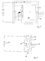
- FIG. 6 shows a battery 10, which is provided to supply an electric motor drive 12. Parallel to the battery 10, a capacitor C1 is connected. About the switching element S1 14, the middle circuit 16 is closed via the switch 18. A possible control of the switching element S 1 and a regulation of the voltage for the drive 12 is in FIG. 6 not shown in detail.
- the parallel to the battery 10 switched capacitor 20 C1 is designed in the known circuit arrangement for receiving the alternating current component occurring during switching of the switching element 14.
- the voltage U C1 applied by the battery to the drive 12 is not stabilized and thus follows the voltage fluctuations resulting from charging and discharging the battery.
- voltage fluctuations of up to +/- 50% of the nominal value of the battery, so that the power components, such as the switching element 18 are interpreted accordingly.
- FIG. 1 shows a first embodiment of the circuit arrangement according to the invention.
- Capacitor 22 C2 Parallel to the already known circuit arrangement, which in FIG. 1 with the same reference numerals as in FIG. 6 is a is Capacitor 22 C2 connected.
- the capacitor C2 is designed to receive energy for the drive 12 as an energy store.
- the capacitor C2 may be formed as a so-called double-layer capacitor, other embodiments are also possible.
- the energy gained can be stored with low loss.
- different approaches are possible: Among other things, it is also possible to provide a pre-charge circuit for the capacitor, so that it can be charged to a desired voltage value.
- the advantage of the precharge circuit is that the capacitor C2 is already available during the first acceleration process after switching on the industrial truck.
- the diode V3 24 is provided for the charging of the capacitor C2.
- the diode V3 24 is provided for the charging of the capacitor C2.
- C2 represents the accumulator for the braking energy, which is charged in conjunction with the diode V3 24 to a voltage level of, for example, 20% above the battery voltage.
- the diode V3 takes on the task that the capacitor C2 can be charged by the generator to a voltage level above the nominal voltage of the battery.
- FIG. 2 shows a possible embodiment and has a power-saving module 26, which is formed with a control unit S2 28.
- the control unit 14 and the control unit 28 are connected to each other via a CAN fieldbus 30. Via the fieldbus 30, driving and operating states of the vehicle determined by the controller S1 are communicated to the controller S2.
- the control unit 28 are at a number of input variables.
- the measured value for the battery voltage U Batt , the supply voltage U C1 and the voltage across the capacitor C2 are present. Furthermore, the current I C2 flowing through the capacitor C2 is present at the control S2.
- the capacitor C2 is connected in series with an inductance L1. Via a switch V1, the capacitor C2 and the inductance L1 is switched completely parallel to the battery 10.
- the battery 10 can be additionally switched on via the switch V3.
- the capacitor C2 In regenerative operation, for example during a braking operation, the capacitor C2 is charged by closing the switch V1 and opening the switches V2 and V3 also to voltage greater than U Batt .
- the capacitor C2 can initially only supply the intermediate circuit until a voltage has dropped to U Batt . Thereafter, switch V3 is closed and the battery takes over the supply.
- the capacitor C2 can be further discharged by switch V3 than in the in FIGS. 1 or 3 illustrated embodiments.
- the intermediate circuit voltage U C1 is additionally supported by the capacitor C2 by switching inductance L1 and switches V1 and V2 as a step-up converter.
- the capacitor C2 is charged via the generator operation of the controller and switch V1 to a voltage level which may be higher than U Batt .
- control unit 28 may provide that power is removed from the battery 10 during a vehicle standstill and a possibly insufficient charge of the capacitor C2 in order to charge the capacitor C2 for the next trip.
- FIG. 3 shows an energy-saving module 30, the energy-saving module 26 in its structural design FIG. 2 equivalent.
- a controller 32 is provided, against which U Batt , U C1 , I C2 and U C2 are present as input variables.
- the controller 32 is connected to the controller 14 via a CAN fieldbus 34.
- Unlike the in FIG. 2 illustrated variant of the energy-saving module 26 is here according to the embodiment FIG. 3 not intended to disconnect the capacitor from the battery during recharging via a switch V3, so that the charging voltage can not be regulated to a value independent of the battery voltage.
- FIG. 4 illustrated variant of an energy-saving module 36 differs from the variant FIG. 3 in that a switch V4 is provided which is connected in parallel with the capacitor C2. In the parallel branch to the capacitor C2, a further additional switch V5 is provided. Switches V4 and V5 are driven by the power-saving module 36, and allow the charging or discharging of the capacitor C2 to occur independently of a voltage change across the battery. In this way, the capacitor C2 can be switched on to keep the voltage U C1 constant at a predetermined value.
- V1, V2, V4, V5 and L1 as boost converter or as buck converter .
- FIG. 5 shows a further embodiment of the invention, in which the energy-saving module 36 from FIG. 4 is brought together with the drive control 14.
- the overall control 38 thus formed assumes the task of the drive control 14 and additionally the control S2 from the energy saving module 36.
- a connection between the two controllers via the CAN bus can be omitted.
- the battery voltage U Batt the voltage U C1 applied to the motor, and the current I C2 flowing through the capacitor C2 and the voltage U C2 applied to the capacitor C2 are again present as input variables.
- the switches V1 and V2 and V4 and V5 for loading and unloading of the capacitor C2 will be switched.
- the controller S2 further switches the switches 40 and 42 to supply the drive 12 in a known manner.
- the capacitor C1 which is provided for smoothing voltage peaks due to the switching operations, is also in FIG. 5 shown.
- the ratio of battery capacity and capacity of the capacitor used depends heavily on the vehicle use. Special advantages arise where the truck is particularly often exposed to braking or acceleration. For industrial trucks whose use allows a high level of energy recovery, the battery capacity can be significantly reduced.
- a central feature of the invention which makes it possible to integrate an additional capacitor C2 in the control of the truck, is that a step-up or step-down converter in the truck is used to support the battery voltage.
Landscapes
- Engineering & Computer Science (AREA)
- Power Engineering (AREA)
- Transportation (AREA)
- Mechanical Engineering (AREA)
- Life Sciences & Earth Sciences (AREA)
- Sustainable Development (AREA)
- Sustainable Energy (AREA)
- Electric Propulsion And Braking For Vehicles (AREA)
- Forklifts And Lifting Vehicles (AREA)
Claims (10)
- Chariot de manutention avec un entraînement électrique (12) qui peut être alimenté par une batterie rechargeable (10), et avec un système de commande pour l'entraînement électrique qui peut commuter l'entraînement (12) vers un fonctionnement comme générateur, dans lequel
un deuxième accumulateur d'énergie (22) est pourvu, dans lequel
le deuxième accumulateur d'énergie peut être chargé dans le fonctionnement de l'entraînement (12) comme générateur, et peut alimenter l'entraînement dans le fonctionnement comme moteur,
caractérisé en ce que
un capteur d'inclinaison est pourvu, le deuxième accumulateur d'énergie étant chargé jusqu'à une tension de charge prédéterminée par la batterie dans des autres conditions de marche et de fonctionnement prédéterminées, le rechargement ayant lieu dépendant de la valeur détectée pour l'inclinaison. - Chariot de manutention selon la revendication 1, caractérisé en ce que le deuxième accumulateur d'énergie peut être chargé à une tension de charge qui est plus grande ou égale à la tension de la batterie.
- Chariot de manutention selon la revendication 1 or 2, caractérisé en ce que dans des conditions de marche et de fonctionnement prédéterminées, l'entraînement électrique est alimenté par le deuxième accumulateur d'énergie et par la batterie.
- Chariot de manutention selon la revendication 1 or 2, caractérisé en ce que dans des conditions de marche et/ou de fonctionnement prédéterminées, l'entraînement électrique est alimenté seulement par le deuxième accumulateur d'énergie.
- Chariot de manutention selon la revendication 3, caractérisé en ce que chez une accélération du véhicule, le deuxième accumulateur d'énergie est activé pour l'alimentation en tension de l'entraînement de marche électrique.
- Chariot de manutention selon la revendication 3, caractérisé en ce que le deuxième accumulateur d'énergie est activé pour l'alimentation en tension de l'entraînement de marche quand une vitesse prédéterminée pour le chariot de manutention est dépassée.
- Chariot de manutention selon l'une quelconque des revendications 1 à 6, caractérisé en ce que dans l'arrêt du véhicule, le deuxième accumulateur d'énergie est chargé en fonction de la valeur d'inclinaison détectée.
- Chariot de manutention selon l'une quelconque des revendications 1 à 7, caractérisé en ce que quand la valeur détectée pour l'inclinaison dépasse une inclinaison minimale, le deuxième accumulateur d'énergie est rechargé jusqu'à une valeur prédéterminée qui est plus petite que la tension de la batterie.
- Chariot de manutention selon l'une quelconque des revendications précédentes, caractérisé en ce que le deuxième accumulateur d'énergie est intégré dans une unité de commande de l'entraînement.
- Chariot de manutention selon l'une quelconque des revendications précédentes, caractérisé en ce que le deuxième accumulateur d'énergie est intégré dans un module d'économie d'énergie (26, qui peut échanger des données avec un système de commande (28) du chariot de manutention via un bus de terrain (30).
Applications Claiming Priority (1)
| Application Number | Priority Date | Filing Date | Title |
|---|---|---|---|
| DE102008007886A DE102008007886A1 (de) | 2008-02-04 | 2008-02-04 | Flurförderzeug mit einem elektrischen Antrieb |
Publications (3)
| Publication Number | Publication Date |
|---|---|
| EP2105342A2 EP2105342A2 (fr) | 2009-09-30 |
| EP2105342A3 EP2105342A3 (fr) | 2011-06-29 |
| EP2105342B1 true EP2105342B1 (fr) | 2016-01-13 |
Family
ID=40795036
Family Applications (1)
| Application Number | Title | Priority Date | Filing Date |
|---|---|---|---|
| EP09001017.4A Ceased EP2105342B1 (fr) | 2008-02-04 | 2009-01-26 | Chariot de manutention doté d'un entraînement électrique |
Country Status (2)
| Country | Link |
|---|---|
| EP (1) | EP2105342B1 (fr) |
| DE (1) | DE102008007886A1 (fr) |
Families Citing this family (6)
| Publication number | Priority date | Publication date | Assignee | Title |
|---|---|---|---|---|
| DE102012219488A1 (de) * | 2012-10-25 | 2014-04-30 | Robert Bosch Gmbh | Schaltungsanordnung und Verfahren zum Vorladen eines kapazitiven Bauelements |
| DE102014104491B4 (de) * | 2014-03-31 | 2025-12-18 | Jungheinrich Aktiengesellschaft | Flurförderzeug mit elektrischem Antrieb |
| DE102014109670A1 (de) * | 2014-07-10 | 2016-01-14 | Jungheinrich Aktiengesellschaft | Flurförderzeug mit einem batteriegespeisten Fahrantrieb sowie ein Verfahren zum Betrieb eines batteriegespeisten Flurförderzeugs |
| DE102015105355B4 (de) * | 2015-04-09 | 2025-10-02 | Jungheinrich Aktiengesellschaft | Antriebseinheit für ein Flurförderzeug |
| DE102020203319B4 (de) | 2020-03-16 | 2025-03-20 | Volkswagen Aktiengesellschaft | Hochvoltsystem |
| CN119705124A (zh) * | 2023-09-27 | 2025-03-28 | 永恒力股份公司 | 电池供电的工业卡车 |
Family Cites Families (5)
| Publication number | Priority date | Publication date | Assignee | Title |
|---|---|---|---|---|
| DE4133303C2 (de) * | 1991-10-08 | 1994-02-17 | Jungheinrich Ag | Anfahrhilfe für Deichselfahrzeuge im Mitgehbetrieb |
| US5710699A (en) * | 1996-05-28 | 1998-01-20 | General Electric Company | Power electronic interface circuits for batteries and ultracapacitors in electric vehicles and battery storage systems |
| DE19628877A1 (de) * | 1996-07-17 | 1998-01-22 | Bayerische Motoren Werke Ag | Verfahren zum Betrieb eines Fahrzeugs mit einer ersten und einer zweiten Antriebs-Energiequelle |
| CA2381035A1 (fr) * | 2002-04-09 | 2003-10-09 | Powergenix Systems, Inc. | Gestion energetique pour systemes de batteries hybrides |
| DE10232639A1 (de) * | 2002-07-18 | 2004-02-12 | Hoerbiger Antriebstechnik Gmbh | Lasttransport-Fahrzeug, insbesondere Gabelstapler |
-
2008
- 2008-02-04 DE DE102008007886A patent/DE102008007886A1/de not_active Withdrawn
-
2009
- 2009-01-26 EP EP09001017.4A patent/EP2105342B1/fr not_active Ceased
Also Published As
| Publication number | Publication date |
|---|---|
| DE102008007886A1 (de) | 2009-08-06 |
| EP2105342A3 (fr) | 2011-06-29 |
| EP2105342A2 (fr) | 2009-09-30 |
Similar Documents
| Publication | Publication Date | Title |
|---|---|---|
| EP2441162B1 (fr) | Réseau de bord pour un véhicule à moteur et procédé pour faire fonctionner un consommateur électrique | |
| EP2705990B1 (fr) | Véhicule automobile doté d'un réseau de bord multi-tension et procédé associé | |
| EP2105342B1 (fr) | Chariot de manutention doté d'un entraînement électrique | |
| DE102017111884B4 (de) | Elektrofahrzeug | |
| DE102009029849A1 (de) | System und Verfahren zum Anlassen einer Maschine | |
| DE102019207601A1 (de) | Stromversorgungssystem für fahrzeug | |
| EP2996898B1 (fr) | Unité d'entraînement pour la commande d'un moteur | |
| DE112009001196T5 (de) | Energieversorgungseinrichtung für ein Fahrzeug sowie Verfahren zum Steuern einer Energieversorgungseinrichtung für ein Fahrzeug | |
| EP2647101B1 (fr) | Dispositif de stockage d'énergie pour un véhicule automobile | |
| DE102013008675A1 (de) | "Energiequellen-Regel- bzw. -Steuergerät für ein Fahrzeug, Verfahren zum Regeln bzw. Steuern eines Energiequellen-Regel- bzw. Steuergerät und Computerprogrammprodukt" | |
| DE102014203030A1 (de) | Verfahren zum gesteuerten Verbinden mehrerer Bordnetzzweige eines Fahrzeugs, Steuereinheit zur Ausführung des Verfahrens sowie Fahrzeugbordnetz | |
| EP1526980B1 (fr) | Source d'entrainement electrique pour entrainement moteur et vehicule moteur pourvu de ladite source | |
| EP3067240B1 (fr) | Procede d'alimentation en tension d'un reseau de bord d'un vehicule automobile | |
| WO2018095801A1 (fr) | Procédé permettant de faire fonctionner une batterie bi-tension | |
| DE10046631A1 (de) | Verfahren zur Regelung der Generatorspannung in einem Kraftfahrzeug | |
| DE102018111681A1 (de) | System für ein elektrisch angetriebenes Fahrzeug sowie Fahrzeug damit und Verfahren dafür | |
| DE102011109709A1 (de) | Verfahren und System zur Spannungsversorgung eines Bordnetzes eines Fahrzeugs | |
| DE112008002650T5 (de) | Brennstoffzellenausgabesteuervorrichtung | |
| WO2016020117A1 (fr) | Système de réseau de bord et procédé pour faire fonctionner un réseau de bord d'un moyen de locomotion à entraînement électrique ayant une pile à combustible | |
| DE102018220809A1 (de) | Verfahren zum Betrieb von wenigstens zwei mit einem Gleichstromnetzwerk verbundenen Pulswechselrichtern, Schaltungsanordnung und Kraftfahrzeug | |
| DE102019132394A1 (de) | Verfahren und Steuerschaltung zum Betreiben eines elektrischen Zusatzspeichers in einem Kraftfahrzeug sowie entsprechendes Kraftfahrzeug | |
| DE102012203219A1 (de) | Verfahren für den Betrieb eines Antriebssystems | |
| DE102007020935A1 (de) | Verfahren und Vorrichtung für die Antriebssteuerung von Hybridfahrzeugen bei hoher Belastung eines elektronischen Energiespeichers | |
| DE102008061583A1 (de) | Elektrisches Antriebssystem für ein Fahrzeug | |
| EP2994339B1 (fr) | Structure de réseau de bord haute-tension pour véhicules |
Legal Events
| Date | Code | Title | Description |
|---|---|---|---|
| PUAI | Public reference made under article 153(3) epc to a published international application that has entered the european phase |
Free format text: ORIGINAL CODE: 0009012 |
|
| AK | Designated contracting states |
Kind code of ref document: A2 Designated state(s): AT BE BG CH CY CZ DE DK EE ES FI FR GB GR HR HU IE IS IT LI LT LU LV MC MK MT NL NO PL PT RO SE SI SK TR |
|
| AX | Request for extension of the european patent |
Extension state: AL BA RS |
|
| PUAL | Search report despatched |
Free format text: ORIGINAL CODE: 0009013 |
|
| AK | Designated contracting states |
Kind code of ref document: A3 Designated state(s): AT BE BG CH CY CZ DE DK EE ES FI FR GB GR HR HU IE IS IT LI LT LU LV MC MK MT NL NO PL PT RO SE SI SK TR |
|
| AX | Request for extension of the european patent |
Extension state: AL BA RS |
|
| RIC1 | Information provided on ipc code assigned before grant |
Ipc: B60L 15/20 20060101ALI20110526BHEP Ipc: B60L 11/18 20060101ALI20110526BHEP Ipc: B60L 11/00 20060101AFI20090827BHEP |
|
| 17P | Request for examination filed |
Effective date: 20111220 |
|
| AKX | Designation fees paid |
Designated state(s): DE FR GB IT SE |
|
| GRAP | Despatch of communication of intention to grant a patent |
Free format text: ORIGINAL CODE: EPIDOSNIGR1 |
|
| INTG | Intention to grant announced |
Effective date: 20150925 |
|
| GRAS | Grant fee paid |
Free format text: ORIGINAL CODE: EPIDOSNIGR3 |
|
| GRAA | (expected) grant |
Free format text: ORIGINAL CODE: 0009210 |
|
| AK | Designated contracting states |
Kind code of ref document: B1 Designated state(s): DE FR GB IT SE |
|
| REG | Reference to a national code |
Ref country code: GB Ref legal event code: FG4D Free format text: NOT ENGLISH |
|
| REG | Reference to a national code |
Ref country code: DE Ref legal event code: R096 Ref document number: 502009012021 Country of ref document: DE |
|
| REG | Reference to a national code |
Ref country code: FR Ref legal event code: PLFP Year of fee payment: 8 |
|
| PG25 | Lapsed in a contracting state [announced via postgrant information from national office to epo] |
Ref country code: IT Free format text: LAPSE BECAUSE OF FAILURE TO SUBMIT A TRANSLATION OF THE DESCRIPTION OR TO PAY THE FEE WITHIN THE PRESCRIBED TIME-LIMIT Effective date: 20160113 |
|
| PG25 | Lapsed in a contracting state [announced via postgrant information from national office to epo] |
Ref country code: SE Free format text: LAPSE BECAUSE OF FAILURE TO SUBMIT A TRANSLATION OF THE DESCRIPTION OR TO PAY THE FEE WITHIN THE PRESCRIBED TIME-LIMIT Effective date: 20160113 |
|
| REG | Reference to a national code |
Ref country code: DE Ref legal event code: R097 Ref document number: 502009012021 Country of ref document: DE |
|
| PLBE | No opposition filed within time limit |
Free format text: ORIGINAL CODE: 0009261 |
|
| STAA | Information on the status of an ep patent application or granted ep patent |
Free format text: STATUS: NO OPPOSITION FILED WITHIN TIME LIMIT |
|
| 26N | No opposition filed |
Effective date: 20161014 |
|
| REG | Reference to a national code |
Ref country code: FR Ref legal event code: PLFP Year of fee payment: 9 |
|
| REG | Reference to a national code |
Ref country code: FR Ref legal event code: PLFP Year of fee payment: 10 |
|
| PGFP | Annual fee paid to national office [announced via postgrant information from national office to epo] |
Ref country code: FR Payment date: 20210127 Year of fee payment: 13 |
|
| PGFP | Annual fee paid to national office [announced via postgrant information from national office to epo] |
Ref country code: GB Payment date: 20210128 Year of fee payment: 13 |
|
| PGFP | Annual fee paid to national office [announced via postgrant information from national office to epo] |
Ref country code: DE Payment date: 20210329 Year of fee payment: 13 |
|
| REG | Reference to a national code |
Ref country code: DE Ref legal event code: R119 Ref document number: 502009012021 Country of ref document: DE |
|
| GBPC | Gb: european patent ceased through non-payment of renewal fee |
Effective date: 20220126 |
|
| PG25 | Lapsed in a contracting state [announced via postgrant information from national office to epo] |
Ref country code: GB Free format text: LAPSE BECAUSE OF NON-PAYMENT OF DUE FEES Effective date: 20220126 Ref country code: DE Free format text: LAPSE BECAUSE OF NON-PAYMENT OF DUE FEES Effective date: 20220802 |
|
| PG25 | Lapsed in a contracting state [announced via postgrant information from national office to epo] |
Ref country code: FR Free format text: LAPSE BECAUSE OF NON-PAYMENT OF DUE FEES Effective date: 20220131 |