EP2105373B1 - Structure à cadre pour véhicule automobile et procédé pour fournir celle-ci - Google Patents
Structure à cadre pour véhicule automobile et procédé pour fournir celle-ci Download PDFInfo
- Publication number
- EP2105373B1 EP2105373B1 EP09003619A EP09003619A EP2105373B1 EP 2105373 B1 EP2105373 B1 EP 2105373B1 EP 09003619 A EP09003619 A EP 09003619A EP 09003619 A EP09003619 A EP 09003619A EP 2105373 B1 EP2105373 B1 EP 2105373B1
- Authority
- EP
- European Patent Office
- Prior art keywords
- frame member
- bend
- vehicle
- frame
- bend portion
- Prior art date
- Legal status (The legal status is an assumption and is not a legal conclusion. Google has not performed a legal analysis and makes no representation as to the accuracy of the status listed.)
- Active
Links
Images


Classifications
-
- B—PERFORMING OPERATIONS; TRANSPORTING
- B62—LAND VEHICLES FOR TRAVELLING OTHERWISE THAN ON RAILS
- B62D—MOTOR VEHICLES; TRAILERS
- B62D21/00—Understructures, i.e. chassis frame on which a vehicle body may be mounted
- B62D21/15—Understructures, i.e. chassis frame on which a vehicle body may be mounted having impact absorbing means, e.g. a frame designed to permanently or temporarily change shape or dimension upon impact with another body
- B62D21/152—Front or rear frames
Definitions
- the present invention relates to a frame structure of an automotive vehicle and a method of providing the same, and in particular, relates to the structure for impact absorption.
- a frame structure of an automotive vehicle comprises, for example, a dash panel which partitions an engine room from a vehicle compartment, and a frame member which is provided in front of the dash panel so as to extend substantially straight in a vehicle longitudinal direction, a rear end portion of which connects to the dash panel.
- the dash panel may retreat in case an impact load is inputted to the frame member in the vehicle longitudinal direction at a vehicle front collision or the like.
- the bend portion is formed by reinforcing one of the sides of the frame member with a reinforcement member in the above-described example, there is need to provide an additional member of the reinforcement member. This would cause a problem of an increase of the number of members.
- EP 1 149 756 A2 discloses a body structure of vehicle according to the preamble of claims 1 and 8 comprising side frames which include widthwise rigidity lowering sections so as to allow inward bending of a rear section of each side frame member.
- US 2006/0 170 206 A1 describes a vehicle front body structure including a hollow front side frame of closed cross-sectional structure and reinforcement beads.
- FR 2 809 072 A1 discloses a structure of box-shaped longitudinal beams in a crash zone of an automotive vehicle.
- An object of the present invention is to provide a frame structure and a method of providing the same which can properly absorb an impact load and, at the same time, be manufactured with low costs.
- a frame structure of an automotive vehicle comprising a frame member which has a substantially rectangular closed cross section and is provided so as to extend substantially straight in a vehicle longitudinal direction, a rear end portion of which connects or is connectable to a dash panel, and a bend portion provided at the frame member, the bend portion being operative to bend in a specified direction substantially in a vehicle width direction when an impact load is inputted to the frame member substantially in the vehicle longitudinal direction, wherein the frame member has different cross sections in the vehicle longitudinal direction in such a manner that a centroid or center of gravity of the bend portion of the frame member is offset to the specified direction of the vehicle width direction from a centroid or center of gravity of a different portion of the frame member from the bend portion, wherein both side faces of the bend portion of the frame member have projections which project outward respectively in such a manner that a projecting height of the projection on a specified side face of the frame member which is located on a side of the specified direction of the vehicle width direction is greater than that of the
- the bend portion of the frame member is offset to the specified direction of the vehicle width direction from the centroid of the different portion of the frame member from the bend portion, the bend portion can be properly provided integrally with the frame member without causing any improper increase of the number of member.
- the frame member and the bend portion are manufactured from only one part. Accordingly, the manufacturing costs can be remarkably reduced due to the reduced number of components and a reduced work load in the assembling procedure.
- centroid or center of gravity is a well-known technical term which is used in the fields of the strength of materials and the like.
- the input of the impact load may cause a moment which functions so as to rotate the cross section of the bend portion relative to the cross section of the different portion from the bend portion in the plan view. Accordingly, the frame member bends properly. In other words, a predetermined bending or buckling of the frame member occurs when an impact load is applied due to the bend portion.
- the frame member comprising a first member and a second member which are located substantially in the vehicle width direction and have a substantially U-shaped cross section respectively, the first and second members being joined to each other via upper and lower flange portions thereof so as to form a substantially closed cross section of the frame member which extends substantially in the vehicle longitudinal direction, and the first and second members preferably have different shapes of the substantially U-shaped cross section in the vehicle longitudinal direction respectively in such a manner that the upper and lower flange portions thereof at the bend portion of the frame member are preferably located offset to the specified direction of the vehicle width direction from the upper and lower flange portions thereof at the different portion of the frame member from the bend portion.
- the offset of the centroid of the bend portion can be materialized easily.
- a joining line of the upper and lower flange portions of the first and second members at a front portion in front of the bend portion of the frame member and a rear portion in back of the bend portion of the frame member extends substantially straight and/or obliquely relative to a longitudinal direction of the frame member in a plan view.
- the flange portions turn from side to side at the bend portion in the vehicle width direction, so that the position of the bend portion can be specified surely.
- the frame member bends surely at the bend portion.
- a plurality of the bend portions of the frame member which are operative to bend in opposite directions of the vehicle width direction to each other are provided, and/or the joining line of the upper and lower flange portions of the first and second members at a portion between the bend portions of the frame member extends substantially straight and/or obliquely relative to the longitudinal direction of the frame member in the plan view.
- the frame member has a substantially rectangular closed cross section which extends substantially in the vehicle longitudinal direction, and/or both side faces of the bend portion of the frame member have beads which are recessed toward an opposite side thereof respectively in such a manner that a depth of the recessed bead on a specified side face of the frame member which is located on a side of the specified direction of the vehicle width direction is preferably shallower than that of the recessed bead on an opposite side face of the frame member to the specified side face.
- the offset of the centroid of the bend portion can be materialized easily.
- respective bottom portions of the recessed beads are joined to each other.
- the impact energy can be properly absorbed by friction of the bottom portions of the recessed beads which occurs at the bending of the frame member.
- a vertical length of the recessed bead on the specified side face of the frame member which is located on the side of the specified direction of the vehicle width direction is smaller than that of the recessed bead on the opposite side face of the frame member to the specified side face.
- the frame member has a substantially rectangular closed cross section which extends substantially in the vehicle longitudinal direction, and both side faces of the bend portion of the frame member have projections which project outward respectively in such a manner that a projecting height of the projection on a specified side face of the frame member which is located on a side of the specified direction of the vehicle width direction is greater than that of the projection on an opposite side face of the frame member to the specified side face.
- a vertical length of the projection on the specified side face of the frame member which is located on the side of the specified direction of the vehicle width direction is greater than that of the projection on the opposite side face of the frame member to the specified side face.
- the bend portion is located so as to be offset from a suspension damper of a suspension member substantially in the vehicle longitudinal direction. Thereby, the bend portion which bends is prevented from interfering with the suspension damper, so that the proper bending of the frame member can be achieved.
- a method of providing a frame structure of an automotive vehicle comprising the steps of:
- the method further comprising the steps of:
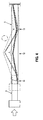
- a vehicle body of an automotive vehicle 1 comprises, as shown in FIG. 1 , a dash panel 4 which partitions an engine room 2 from a vehicle compartment 3, a pair of front side frames 5, 5 which extend straight in a vehicle longitudinal direction in front of the dash panel 4 on both (left and right) sides, rear end portions of which connect to the dash panel 4, a bumper reinforcement 7 which is provided at front end portions of the front side frames 5, 5 via crush cans 6, 6, hinge pillars 8, 8 which are provided at both-side end portions of the dash panel 4 so as to extend vertically and support front end portions of front doors (not illustrated), a dash reinforcement 9 which is provided at a back face of the dash panel 4 so as to interconnect the both-side hinge pillars 8, 8, side sills 10, 10 which connect to the lower ends of the hinge pillars 8, 8 at front end portions thereof and extend rearward, and floor frames 12, 12 which extend in the vehicle longitudinal direction below the floor panel 11 which forms a floor face of the vehicle compartment 3, front end potions of which
- the impact load when the impact load is inputted to the bumper reinforcement 7 via a bumper face 13 and the like at a vehicle front collision or the like, it is transmitted so as to disperse to members of a vehicle body 4-12 via the crush cans 6, 6 and front side frames 5, 5.
- the crush cans 6 crush in an axial direction thereof.
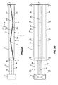
- the front side frame 5 has at least one bend portion, preferably a plurality of bend portions T1-T3, which are operative to bend in a vehicle width direction due to the impact load being inputted (see FIG. 4 ).
- bend portions T1-T3 which are operative to bend in a vehicle width direction due to the impact load being inputted (see FIG. 4 ).
- the crush can 6 is preferably made of aluminum material, for example, and it has an upper face portion 6a, a lower face portion 6b, and left and right side face portions 6c, 6d so as to form a rectangular closed cross section which extends substantially straight in the vehicle longitudinal direction.
- At both side face portions 6c, 6d are preferably formed beads 6e, 6f which are recessed toward their opposite side face portions 6d, 6c respectively and extend in the vehicle longitudinal direction.
- the depth d1, d2 and the vertical length h1, h2 of these beads 6e, 6f are preferably the same respectively.
- the cross section of the crush can is preferably symmetrical.
- the thickness and the like of the crush can 6 is configured such that the crush can 6 crushes in an axis direction (a longitudinal direction of the crush can 6) so as to have a compressive deformation in bellows shape when the impact load is inputted substantially in the vehicle longitudinal direction.
- the front side frame 5 preferably comprises, as shown in FIGS. 2A, 2B , 3C-3E , a first member 21 which preferably includes an upper face portion 21a, a lower face portion 21b, a side face portion 21c and upper and lower flange portions 21d, 21e so as to have a substantially U-shaped cross section, and a second member 22 which preferably includes an upper face portion 22a, a lower face portion 22b, a side face portion 22c and upper and lower flange portions 22d, 22e so as to have a substantially U-shaped cross section.
- the upper flange portions 21d, 22d and the lower flange portions 21e, 22e of the first and second members 21, 22 are preferably joined to each other respectively so as to provide the substantially rectangular closed cross section which extends substantially straight in the vehicle longitudinal direction.
- beads 21f, 22f which are preferably recessed toward their opposite side face portions 22c, 21c respectively and extend in the vehicle longitudinal direction. These beads 21f, 22f are provided to strengthen the function of absorption of the impact load by the front side frame 5.
- the bend portion T1 is preferably provided at a connection portion of the crush can 6 to the front side frame 5, specifically at the front end of the front side frame 5.
- This bend portion T1 is preferably configured by a difference in the rigidity between the crush can 6 and the front side frame 5.
- a front end 5a of the front side frame 5 is preferably formed so as to be slant in such a manner that its outward portion is positioned rearward from its inward portion. Thereby, the front side frame 5 bends outward at the bend portion T2.
- centroid of the bend portions T2, T3 of the front side frame 5 is offset to a specified direction of the vehicle width direction from the centroid of the different portion of the front side frame 5 from the bend portions T2, T3.
- the upper flange portions 21d, 22d and the lower flange portions 21e, 22e at the bend portion T2 are preferably located offset to the above-described specified direction of the vehicle width direction, i.e., outward of the vehicle, from the upper and lower flange portions 21d, 22d, 21e, 22e at the different portion from the bend portion T2.
- a vertical length h3 of the bead 21f is preferably the same as a vertical length h4 of the bead 22f (which is the same as other portions in the longitudinal direction)
- a depth d1 of the outside bead 21f is preferably shallower than a depth d2 of the inside bead 22f.
- the centroid Z of the bend portion T2 is offset toward the side of the side face portion 21c of the first member 21 from a middle (center) position C between the side face portions 21c, 22c of the front side frame 5.
- the centroid Z of the bend portion T2 is offset outward of the vehicle from the centroid Z of the different portion from the bend portion T2.
- the vehicle has a suspension damper D of a suspension member which is located outside the front side frame 5, and the bend portion T2 is located so as to be offset from the suspension damper D in the vehicle longitudinal direction. Thereby, the bend portion T2 which bends is prevented from interfering with the suspension damper D.
- the upper flange portions 21d, 22d and the lower flange portions 21e, 22e at the bend portion T3 are preferably located offset to the above-described specified direction of the vehicle width direction, i.e., inward of the vehicle because the bending direction of the bend portion T3 is opposite to that of the above-described bend portion T2, from the upper and lower flange portions 21d, 22d, 21e, 22e at the different portion from the bend portion T3.
- a depth d2 of the inside bead 22f is preferably shallower than a depth d1 of the outside bead 21f.
- centroid Z of the bend portion T3 is offset toward the side of the side face portion 22c of the second member 22 from the middle (center) position C between the side face portions 21c, 22c of the front side frame 5. That is, the centroid Z of the bend portion T3 is preferably offset inward of the vehicle from the centroid Z of the different portion from the bend portion T3.
- the upper flange portions 21d, 22d and the lower flange portions 21e, 22e at a portion of the front side frame 5 which is positioned near its connection portion to the dash panel 4 are preferably located similarly to the bend portion T2.
- a depth d1 of the outside bead 21f is substantially the same as a depth d2 of the inside bead 22f.
- the front side frame 5 does not bend at this portion near the connection portion to the dash panel.
- a joining line of the upper flange portions 21d, 22d and the lower flange portions 21e, 22e at a portion of the front side frame 5 between the bend portions T2, T3 extends substantially straight and/or obliquely relative to a longitudinal direction of the front side frame 5 in the plan view.
- the beads 21f, 22f preferably have bottom portions 21g, 22g respectively which are formed at the side face portions 21c, 22c, and these bottom portions 21g, 22g are preferably joined to each other at the bend portions T2, T3.
- the crush can 6 crushes so as to deform in the axis direction and the front side frame 5 bends substantially in the vehicle width direction at the bend portions T1-T3 as shown by broken lines in FIG. 4 .
- the bend portions T2, T3 of the front side frame 5 is offset in the vehicle width direction from the centroid Z of the different portion of the front side frame 5 from the bend portions T2, T3, the bend portions T2, T3 can be properly provided without causing any improper increase of the number of member.
- the above-described offset of the centroid of the bend portions T2, T3 can be materialized easily by the structure in which the upper flange portions 21d, 22d and the lower flange portions 21e, 22e at the bend portions T2, T3 are located offset to the above-described specified direction of the vehicle width direction from the upper flange portions 21d, 22d and the lower flange portions 21e, 22e at the different portion of the front side frame 5 from the bend portions T2, T3.
- the plural bend portions T2, T3 operative to bend in the opposite directions of the vehicle width direction to each other are provided, and the joining line of the upper flange portions 21d, 22d and the lower flange portions 21e, 22e at the portion between the bend portions T2, T3 extends substantially straight and/or obliquely relative to the longitudinal direction of the front side frame 5 in the plan view, the bending of the front side frame 5 can be achieved easily compared to a case in which the joining line of the flange portions extends in a curve shape.
- the offset of the centroid of the bend portions T2, T3 can be materialized easily by the structure in which the depth of the beads 21f, 22f is different from each other.
- the impact energy can be properly absorbed by friction of the bottom portions 21g, 22g which occurs at the bending of the front side frame 5. Further, the deformation of the side face portions 21c, 22c of the beads 21f, 22f can be controlled properly.
- both the offset joining line provision of the upper flange portions 21d, 22d and the lower flange portions 21e, 22e and the different depth d1 , d2 of the beads 21f, 22f are provided to make the offset provision of the centroid Z in the above-described comparative example, either one of these may be applied for the offset of the centroid Z.
- the strength of the front side frame 5 may be considered for this application.
- the bend portions T2, T3 of a first member 21' and a second member 22' which forms a front side frame 5' has vertical beads 21h', 22h' on their side face portions 21c', 22c'.
- the vertical beads 21h', 22h' preferably extend substantially vertically and are preferably recessed in the bending direction of the bend portions T2, T3, respectively. Thereby, the front side frame 5' bends surely at the bend portions T2, T3.
- a front side frame 5" has a narrower width W than the first and second comparative examples as shown in FIG. 6 . This is because this frame 5" may be properly applied to a relatively narrow layout space for the frame 5" at the front portion of the vehicle.
- a vertical length h3 of a bead 21f" of a first member 21" which forms a front side frame 5" is not equal to a vertical length h4 of a bead 22f" of a second member 22".
- the centroid Z can be positioned to be offset more toward the first member 21" compared to the case in which the both vertical lengths are equal to each other. Thereby, the offset of the centroid Z can be achieved properly even in case the width W of the front side frame 5 is considerably small.
- a crush can 106 has an upper face portion 106a, a lower face portion 106b and side face potions 106c, 106d so as to form a substantially rectangular closed cross section which extends substantially straight in the vehicle longitudinal direction.
- the both side face portions 106c, 106d have projections 106e, 106f which project outward respectively. Heights d1, d2 and vertical lengths h1, h2 of the projections 106e, 106f are preferably substantially equal to each other, respectively, such that the cross section of the crush can 106 is symmetrical.
- the thickness and the like of the crush can 106 is preferably configured such that the crush can 10 crushes in the axis direction (longitudinal direction of the crush can 106 ) so as to have the compressive deformation in bellows shape when the impact load is inputted in the vehicle longitudinal direction.
- the front side frame 105 preferably comprises, as shown in FIGS. 7A, 7B , 8C-8E , a first member 121 which preferably includes an upper face portion 121a, a lower face portion 121b, a side face portion 121c and upper and lower flange portions 121d, 121e so as to have a substantially U-shaped cross section, and a second member 122 which preferably includes an upper face portion 122a, a lower face portion 122b, a side face portion 122c and upper and lower flange portions 122d, 122e so as to have a substantially U-shaped cross section.
- the upper flange portions 121d, 122d and the lower flange portions 121e, 122e of the first and second members 121, 122 are preferably joined to each other respectively so as to provide the substantially rectangular closed cross section which extends substantially straight in the vehicle longitudinal direction.
- both side face portions 121c, 122c of the first and second members 121, 122 are preferably formed projections 121f, 122f which project preferably toward the opposite sides to the side face portions 122c, 121c respectively and extend preferably substantially in the vehicle longitudinal direction. These projections 121f, 122f are provided to strengthen the function of absorption of the impact load by the front side frame 105.
- the bend portion T1 is preferably provided at a connection portion of the crush can 106 to the front side frame 105, specifically substantially at the front end of the front side frame 105.
- This bend portion T1 is preferably configured by a difference in the rigidity between the crush can 106 and the front side frame 105.
- a front end 105a of the front side frame 105 is preferably formed so as to be slant in such a manner that its outward portion is positioned rearward from its inward portion. Thereby, the front side frame 105 bends outward at the bend portion T2.
- the upper flange portions 121d, 122d and the lower flange portions 121e, 122e at the bend portion T2 are preferably located offset to the above-described specified direction of the vehicle width direction, i.e., outward of the vehicle, from the upper and lower flange portions 121d, 122d, 121e, 122e at the different portion from the bend portion T2.
- a height d1 of the outside projection 121f is preferably greater than a height d2 of the inside projection 122f (the height d2 is zero at this portion).
- the centroid Z of the bend portion T2 is preferably offset outward of the vehicle from the centroid Z of the different portion from the bend portion T2.
- the upper flange portions 121d, 122d and the lower flange portions 121e, 122e at the bend portion T3 are preferably located offset to the above-described specified direction of the vehicle width direction, i.e., inward of the vehicle from the upper and lower flange portions 121d, 122d, 121e, 122e at the different portion from the bend portion T3 (similar to the above-described first embodiment regarding the flange portions).
- the height d2 of the inside projection 122f is preferably greater than the height d1 of the outside projection 121f (the height d1 is zero at this portion).
- the centroid Z of the bend portion T3 is preferably offset inward of the vehicle from the centroid Z of the different portion from the bend portion T3.
- the upper flange portions 121d, 122d and the lower flange portions 121e, 122e at a portion of the front side frame 105 which is positioned near its connection portion to the dash panel 4 are preferably located similarly to the bend portion T2.
- a height d1 of the outside projection 121f is preferably substantially the same as a height d2 of the inside projection 122f.
- the front side frame 105 does not bend at this portion near the connection portion to the dash panel.
- the offset of the centroid Z of the bend portions T2, T3 can be materialized easily by the structure in which the height of the projections 121f, 122f is different from each other.
- the vertical length may be set to be different from each other like the above-described third embodiment.
- the centroid may be offset properly, restraining the projection height.
- the present invention is applicable to any case in which the front side frame bends vertically or in any angle direction between the lateral direction and the vertical direction.
- the combination of these may be applied in such a manner that the projection is formed at the bending-direction side and the recessed bead is formed at the other side.
Landscapes
- Engineering & Computer Science (AREA)
- Chemical & Material Sciences (AREA)
- Combustion & Propulsion (AREA)
- Transportation (AREA)
- Mechanical Engineering (AREA)
- Body Structure For Vehicles (AREA)
Claims (9)
- Structure à cadre d'un véhicule automobile (1), comprenant :un élément de cadre (105) qui présente une section transversale fermée sensiblement rectangulaire et est fourni de manière à s'étendre de manière sensiblement en ligne droite dans une direction longitudinale du véhicule, une partie d'extrémité arrière de celui-ci est reliée ou peut être reliée à un tableau de bord (4) ; etune partie de coude (T2, T3) fournie sur l'élément de cadre (105), la partie de coude (T2, T3) étant efficace pour plier dans une direction spécifiée sensiblement dans une direction de largeur du véhicule lorsqu'une charge d'impact est appliquée à l'élément de cadre (5 ; 5'; 5" ; 105) sensiblement dans la direction longitudinale du véhicule,dans laquelle ledit élément de cadre (105) présente différentes sections transversales dans la direction longitudinale du véhicule de telle sorte qu'un centroïde (Z) de ladite partie de coude (T2, T3) de l'élément de cadre (105) est décalé par rapport à ladite direction spécifiée de la direction de largeur du véhicule depuis un centroïde (Z) d'une partie différente de l'élément de cadre (105) depuis la partie de coude (T2, T3),caractérisée en ce queles deux faces latérales (121c, 122c) de ladite partie de coude (T2 ou T3) de l'élément de cadre (105) présentent des saillies (121f, 122f) qui ressortent vers l'extérieur respectivement de telle sorte qu'une hauteur en saillie (d1 ou d2) de la saillie (121f ou 122f) sur une face latérale spécifiée (121c ou 122c) de l'élément de cadre (105) qui est située sur une face de ladite direction spécifiée de la direction de largeur de véhicule est supérieure à celle (d2 ou d1) de la saillie (122f ou 121f) sur une face latérale opposée (122c ou 121c) de l'élément de cadre (105) par rapport à ladite face latérale spécifiée (121c ou 122c).
- Structure à cadre d'un véhicule automobile (1) selon la revendication 1, dans laquelle ledit élément de cadre (105) comprend un premier élément (121) et un second élément (122) qui sont situés sensiblement dans la direction de largeur du véhicule et présentent une section transversale sensiblement en forme de U, le premier élément et le second élément (121, 122) étant reliés l'un à l'autre via des parties de brides supérieures et inférieures (121d, 122d, 121e, 122e) de ceux-ci pour former une section transversale sensiblement fermée de l'élément de cadre (105) qui s'étend sensiblement dans la direction longitudinale du véhicule, et lesdits premier et second éléments (121, 122) présentent de préférence des formes différentes de la section transversale sensiblement en U dans la direction longitudinale du véhicule respectivement de telle sorte que les parties de brides supérieures et inférieures (121d, 122d, 121e, 122e) de ceux-ci sur ladite partie de coude (T2, T3) de l'élément de cadre (105) sont de préférence situées décalées par rapport à ladite direction spécifiée de la direction de largeur du véhicule depuis les parties de bride supérieures et inférieures (121d, 122d, 121e, 122e) de ceux-ci sur la partie différente de l'élément de cadre (105) depuis la partie de coude (T2, T3).
- Structure à cadre d'un véhicule automobile (1) selon la revendication 2, dans laquelle une ligne de jonction desdites parties de brides supérieures et inférieures (121d, 122d, 121e, 122e) des premier et second éléments (121, 122) sur une partie avant à l'avant de ladite partie de coude (T2, T3) de l'élément de cadre (105) et une partie arrière à l'arrière de ladite partie de coude (T2, T3) de l'élément de cadre (105) s'étend sensiblement en ligne droite et/ou oblique par rapport à une direction longitudinale de l'élément de cadre (105) dans une vue en plan.
- Structure à cadre d'un véhicule automobile (1) selon une quelconque ou plusieurs des revendications précédentes, dans laquelle est fournie une pluralité desdites parties de coude (T2, T3) de l'élément de cadre (105) qui sont efficaces pour plier les unes par rapport aux autres dans des directions opposées de la direction de largeur du véhicule, et/ou la ligne de jonction des parties de brides supérieures et inférieures (121d, 122d, 121e, 122e) des premier et second éléments (121, 122) sur une partie entre les parties de coude (T2, T3) de l'élément de cadre (105) s'étend sensiblement en ligne droite et/ou oblique par rapport à la direction longitudinale de l'élément de cadre (105) dans une vue en plan.
- Structure à cadre d'un véhicule automobile (1) selon une quelconque ou plusieurs des revendications précédentes, dans laquelle une longueur verticale (h3 ou h4) de la saillie (121f ou 122f) sur la face latérale spécifiée (121c ou 122c) de l'élément de cadre (105) qui est située sur la face de ladite direction spécifiée de la direction de largeur du véhicule est supérieure à celle (h4 ou h3) de la saillie (122f ou 121f) sur la face latérale opposée (122c ou 121c) de l'élément de cadre (105) par rapport à la face latérale spécifiée (121c ou 122c).
- Structure à cadre d'un véhicule automobile (1) selon une quelconque ou plusieurs des revendications précédentes, dans laquelle ladite partie de coude (T2) est située de manière à être décalée sensiblement dans la direction longitudinale du véhicule depuis un amortisseur de suspension (D) d'un élément de suspension du véhicule (1) qui est situé à l'extérieur dudit élément de cadre (105).
- Structure à cadre d'un véhicule automobile (1) selon une quelconque ou plusieurs des revendications précédentes, dans laquelle une gaine d'écrasement (106) ayant sensiblement la même section transversale que le cadre latéral avant (105) sur une partie avant de celui-ci est fournie sur ladite partie avant dudit cadre latéral avant (105).
- Procédé de fourniture d'une structure à cadre d'un véhicule automobile (1), comprenant les étapes suivantes :fourniture d'un élément de cadre (105) présentant une section transversale fermée sensiblement rectangulaire pour s'étendre de manière sensiblement droite dans une direction longitudinale du véhicule, une partie d'extrémité arrière de celui-ci est reliée ou peut être reliée à un tableau de bord (4) ; etfourniture d'une partie de coude (T2, T3) sur l'élément de cadre (105), la partie de coude (T2, T3) étant efficace pour plier dans une direction spécifiée sensiblement dans une direction de largeur du véhicule lorsqu'une charge d'impact est appliquée à l'élément de cadre (105) sensiblement dans la direction longitudinale du véhicule, etformation dudit élément de cadre (105) de telle sorte qu'il présente différentes sections transversales dans la direction longitudinale du véhicule de telle sorte qu'un centroïde (Z) de ladite partie de coude (T2, T3) de l'élément de cadre (105) est décalé par rapport à ladite direction spécifiée de la direction de largeur du véhicule depuis un centroïde (Z) d'une partie différente de l'élément de cadre (105) depuis la partie de coude (T2, T3),caractérisé parla formation de saillies (121f, 122f) sur les deux faces latérales (121c, 122c) de ladite partie de coude (T2 ou T3) de l'élément de cadre (105) telle que les saillies (121f, 122f) ressortent vers l'extérieur respectivement de telle sorte qu'une hauteur en saillie (d1 ou d2) de la saillie (121f ou 122f) sur une face latérale spécifiée (121c ou 122c) de l'élément de cadre (105) qui est située sur une face de ladite direction spécifiée de la direction de largeur de véhicule est supérieure à celle (d2 ou d1) de la saillie (122f ou 121f) sur une face latérale opposée (122c ou 121c) de l'élément de cadre (105) par rapport à ladite face latérale spécifiée (121c ou 122c).
- Procédé de fourniture d'une structure à cadre selon la revendication 8, comprenant en outre les étapes suivantes :fourniture au dit élément de cadre (105) d'un premier élément (121) et d'un second élément (122) qui sont situés sensiblement dans la direction de largeur du véhicule et présentent une section transversale sensiblement en forme de U respectivement,la liaison du premier élément et du second élément (121, 122) entre eux via des parties de brides supérieures et inférieures (121d, 122d, 121e, 122e) de ceux-ci pour former une section transversale sensiblement fermée de l'élément de cadre (105) qui s'étend sensiblement dans la direction longitudinale du véhicule, lesdits premier et second éléments (121, 122) présentant de préférence des formes différentes de la section transversale sensiblement en U dans la direction longitudinale du véhicule respectivement de telle sorte que les parties de brides supérieures et inférieures (121d, 122d, 121e, 122e) de ceux-ci sur ladite partie de coude (T2, T3) de l'élément de cadre (105) sont de préférence situées décalées par rapport à ladite direction spécifiée de la direction de largeur du véhicule depuis les parties de brides supérieures et inférieures (121d, 122d, 121e, 122e) de ceux-ci sur la partie différente de l'élément de cadre (105) depuis la partie de coude (T2, T3).
Applications Claiming Priority (1)
| Application Number | Priority Date | Filing Date | Title |
|---|---|---|---|
| JP2008074843A JP2009227104A (ja) | 2008-03-24 | 2008-03-24 | 自動車のフレーム構造 |
Publications (2)
| Publication Number | Publication Date |
|---|---|
| EP2105373A1 EP2105373A1 (fr) | 2009-09-30 |
| EP2105373B1 true EP2105373B1 (fr) | 2011-01-26 |
Family
ID=40636898
Family Applications (1)
| Application Number | Title | Priority Date | Filing Date |
|---|---|---|---|
| EP09003619A Active EP2105373B1 (fr) | 2008-03-24 | 2009-03-12 | Structure à cadre pour véhicule automobile et procédé pour fournir celle-ci |
Country Status (4)
| Country | Link |
|---|---|
| US (1) | US20090236166A1 (fr) |
| EP (1) | EP2105373B1 (fr) |
| JP (1) | JP2009227104A (fr) |
| DE (1) | DE602009000653D1 (fr) |
Families Citing this family (26)
| Publication number | Priority date | Publication date | Assignee | Title |
|---|---|---|---|---|
| US8539737B2 (en) | 2008-09-19 | 2013-09-24 | Ford Global Technologies, Llc | Twelve-cornered strengthening member |
| WO2012026028A1 (fr) * | 2010-08-26 | 2012-03-01 | トヨタ自動車株式会社 | Structure de bras oscillant pour une carrosserie de véhicule |
| JP5783261B2 (ja) * | 2011-10-25 | 2015-09-24 | トヨタ自動車株式会社 | 骨格部材 |
| EP2783948A1 (fr) * | 2011-11-22 | 2014-10-01 | Toyota Jidosha Kabushiki Kaisha | Structure pour partie latérale de carrosserie de véhicule |
| JP5596753B2 (ja) * | 2012-08-03 | 2014-09-24 | アイシン精機株式会社 | 衝撃吸収部材 |
| JP6252080B2 (ja) * | 2013-10-02 | 2017-12-27 | 日産自動車株式会社 | 自動車の車体前部構造 |
| JP6206331B2 (ja) * | 2014-06-02 | 2017-10-04 | マツダ株式会社 | 車両用フレーム構造 |
| JP6102870B2 (ja) * | 2014-09-19 | 2017-03-29 | トヨタ自動車株式会社 | 車体前部構造 |
| JP6107850B2 (ja) * | 2015-02-27 | 2017-04-05 | マツダ株式会社 | 車両用フレーム構造 |
| US10315698B2 (en) | 2015-06-24 | 2019-06-11 | Ford Global Technologies, Llc | Sixteen-cornered strengthening member for vehicles |
| US9944323B2 (en) | 2015-10-27 | 2018-04-17 | Ford Global Technologies, Llc | Twenty-four-cornered strengthening member for vehicles |
| KR101844638B1 (ko) * | 2015-11-27 | 2018-04-02 | 르노삼성자동차 주식회사 | 차량용 후방 사이드 부재 |
| US9889887B2 (en) | 2016-01-20 | 2018-02-13 | Ford Global Technologies, Llc | Twelve-cornered strengthening member for a vehicle with straight and curved sides and an optimized straight side length to curved side radius ratio |
| US9789906B1 (en) * | 2016-03-23 | 2017-10-17 | Ford Global Technologies, Llc | Twenty-eight-cornered strengthening member for vehicles |
| US10704638B2 (en) | 2016-04-26 | 2020-07-07 | Ford Global Technologies, Llc | Cellular structures with twelve-cornered cells |
| US10393315B2 (en) | 2016-04-26 | 2019-08-27 | Ford Global Technologies, Llc | Cellular structures with twelve-cornered cells |
| US10473177B2 (en) | 2016-08-23 | 2019-11-12 | Ford Global Technologies, Llc | Cellular structures with sixteen-cornered cells |
| US10220881B2 (en) | 2016-08-26 | 2019-03-05 | Ford Global Technologies, Llc | Cellular structures with fourteen-cornered cells |
| US10279842B2 (en) | 2016-08-30 | 2019-05-07 | Ford Global Technologies, Llc | Twenty-eight-cornered strengthening member for vehicles |
| US10300947B2 (en) | 2016-08-30 | 2019-05-28 | Ford Global Technologies, Llc | Twenty-eight-cornered strengthening member for vehicles |
| US10429006B2 (en) | 2016-10-12 | 2019-10-01 | Ford Global Technologies, Llc | Cellular structures with twelve-cornered cells |
| CN110475706B (zh) * | 2017-03-31 | 2022-06-14 | 日本制铁株式会社 | 汽车的冲击吸收构件和纵梁 |
| GB2569582B (en) * | 2017-12-20 | 2020-06-17 | Ford Global Tech Llc | A powertrain support mount assembly |
| EP3569479B1 (fr) * | 2018-05-15 | 2024-04-03 | Volvo Car Corporation | Sous-cadre pour véhicule |
| US11292522B2 (en) | 2019-12-04 | 2022-04-05 | Ford Global Technologies, Llc | Splayed front horns for vehicle frames |
| KR102468039B1 (ko) * | 2020-11-18 | 2022-11-17 | 주식회사 포스코 | 차량용 프런트 사이드 멤버 |
Family Cites Families (19)
| Publication number | Priority date | Publication date | Assignee | Title |
|---|---|---|---|---|
| JPS5029209B2 (fr) * | 1971-12-08 | 1975-09-22 | ||
| JPS61287871A (ja) * | 1985-06-17 | 1986-12-18 | Toyota Motor Corp | 自動車のサイドメンバ |
| JP2595724B2 (ja) * | 1989-08-30 | 1997-04-02 | 日産自動車株式会社 | 強度部材の製造方法 |
| JP2921183B2 (ja) * | 1991-07-26 | 1999-07-19 | トヨタ自動車株式会社 | 自動車の前部車体構造 |
| US5370438A (en) * | 1991-10-31 | 1994-12-06 | Toyota Jidosha Kabushiki Kaisha | Structural member of automobile |
| JPH0885472A (ja) * | 1994-09-19 | 1996-04-02 | Honda Motor Co Ltd | 自動車のフロントサイドフレーム構造 |
| JPH08108863A (ja) * | 1994-10-12 | 1996-04-30 | Honda Motor Co Ltd | 自動車のフロントサイドフレーム構造 |
| US5431445A (en) * | 1994-11-28 | 1995-07-11 | Ford Motor Company | Asymmetrical beam structure for a vehicle |
| ES2176911T3 (es) * | 1997-06-30 | 2002-12-01 | Mazda Motor | Estructura delantera de carroceria para vehiculo. |
| US6655728B2 (en) * | 2000-04-25 | 2003-12-02 | Nissan Motor Co., Ltd. | Body structure of vehicle |
| FR2809072B1 (fr) * | 2000-05-19 | 2002-11-01 | Renault | Ensemble de structure de caisse comportant des longerons munis de zones d'amorce de pliage |
| JP3882629B2 (ja) | 2002-01-31 | 2007-02-21 | 日産自動車株式会社 | 自動車用衝撃吸収構造 |
| US6695393B1 (en) * | 2002-09-18 | 2004-02-24 | Ford Global Technologies, Llc | Kinetic energy absorbing rail for an automotive frame |
| JP4281555B2 (ja) * | 2004-01-13 | 2009-06-17 | トヨタ自動車株式会社 | 車体構造体 |
| JP4594123B2 (ja) * | 2005-02-03 | 2010-12-08 | 本田技研工業株式会社 | 車体前部構造 |
| US7380830B2 (en) * | 2005-02-03 | 2008-06-03 | Honda Motor Co., Ltd. | Vehicle front body structure |
| US7261345B2 (en) * | 2005-02-03 | 2007-08-28 | Akad Osman E | Impact energy absorbing crash cushion |
| JP2007230268A (ja) * | 2006-02-27 | 2007-09-13 | Toyota Motor Corp | 車両骨格部材 |
| US7717465B2 (en) * | 2007-01-11 | 2010-05-18 | Ford Motor Company | Vehicle having an engine support structure |
-
2008
- 2008-03-24 JP JP2008074843A patent/JP2009227104A/ja active Pending
-
2009
- 2009-02-20 US US12/389,923 patent/US20090236166A1/en not_active Abandoned
- 2009-03-12 DE DE602009000653T patent/DE602009000653D1/de active Active
- 2009-03-12 EP EP09003619A patent/EP2105373B1/fr active Active
Also Published As
| Publication number | Publication date |
|---|---|
| DE602009000653D1 (de) | 2011-03-10 |
| EP2105373A1 (fr) | 2009-09-30 |
| US20090236166A1 (en) | 2009-09-24 |
| JP2009227104A (ja) | 2009-10-08 |
Similar Documents
| Publication | Publication Date | Title |
|---|---|---|
| EP2105373B1 (fr) | Structure à cadre pour véhicule automobile et procédé pour fournir celle-ci | |
| US8002064B2 (en) | Frame structure of automotive vehicle | |
| EP1555191B1 (fr) | Structure d'un élément de chassis de véhicule absorbant l'énergie d'un choc | |
| AU705222B2 (en) | Front structure of car body, and method of absorbing impact by means of the front structure | |
| CN101977786B (zh) | 车门构造体及其制造方法 | |
| US20050194818A1 (en) | Vehicle body floor structure | |
| JP4752411B2 (ja) | 車体骨格構造 | |
| US9889888B2 (en) | Side body structure of vehicle | |
| JP6256518B2 (ja) | 車両の側部車体構造 | |
| JP2007314131A (ja) | 車体下部構造 | |
| JP5533587B2 (ja) | 車両のサイドシル構造 | |
| WO2018016174A1 (fr) | Structure de section avant de châssis de véhicule | |
| CN111284564A (zh) | 车身结构 | |
| JP2011136593A (ja) | フロントピラー下部構造 | |
| JP2010111169A (ja) | 車体前部構造 | |
| JP6256520B2 (ja) | 車両の側部車体構造 | |
| JP5630575B2 (ja) | 車両用構造体 | |
| WO2018029941A1 (fr) | Structure de carrosserie de véhicule | |
| JP7627341B2 (ja) | 車両用フロントサイドメンバー | |
| JP6256517B2 (ja) | 車両の側部車体構造 | |
| JP4431161B2 (ja) | 側面衝突性能を強化させた自動車用ドア | |
| JP7443979B2 (ja) | 車両の前部車体構造 | |
| JP6961524B2 (ja) | 車両のフロントピラー補強構造 | |
| JP6048678B2 (ja) | 車両の側部車体構造 | |
| JP7676921B2 (ja) | 車両の下部車体構造 |
Legal Events
| Date | Code | Title | Description |
|---|---|---|---|
| PUAI | Public reference made under article 153(3) epc to a published international application that has entered the european phase |
Free format text: ORIGINAL CODE: 0009012 |
|
| AK | Designated contracting states |
Kind code of ref document: A1 Designated state(s): AT BE BG CH CY CZ DE DK EE ES FI FR GB GR HR HU IE IS IT LI LT LU LV MC MK MT NL NO PL PT RO SE SI SK TR |
|
| AX | Request for extension of the european patent |
Extension state: AL BA RS |
|
| 17P | Request for examination filed |
Effective date: 20091112 |
|
| 17Q | First examination report despatched |
Effective date: 20091207 |
|
| AKX | Designation fees paid |
Designated state(s): DE |
|
| GRAP | Despatch of communication of intention to grant a patent |
Free format text: ORIGINAL CODE: EPIDOSNIGR1 |
|
| GRAS | Grant fee paid |
Free format text: ORIGINAL CODE: EPIDOSNIGR3 |
|
| GRAA | (expected) grant |
Free format text: ORIGINAL CODE: 0009210 |
|
| AK | Designated contracting states |
Kind code of ref document: B1 Designated state(s): DE |
|
| REF | Corresponds to: |
Ref document number: 602009000653 Country of ref document: DE Date of ref document: 20110310 Kind code of ref document: P |
|
| REG | Reference to a national code |
Ref country code: DE Ref legal event code: R096 Ref document number: 602009000653 Country of ref document: DE Effective date: 20110310 |
|
| REG | Reference to a national code |
Ref country code: DE Ref legal event code: R084 Ref document number: 602009000653 Country of ref document: DE Effective date: 20110831 |
|
| PLBE | No opposition filed within time limit |
Free format text: ORIGINAL CODE: 0009261 |
|
| STAA | Information on the status of an ep patent application or granted ep patent |
Free format text: STATUS: NO OPPOSITION FILED WITHIN TIME LIMIT |
|
| 26N | No opposition filed |
Effective date: 20111027 |
|
| REG | Reference to a national code |
Ref country code: DE Ref legal event code: R097 Ref document number: 602009000653 Country of ref document: DE Effective date: 20111027 |
|
| PGFP | Annual fee paid to national office [announced via postgrant information from national office to epo] |
Ref country code: DE Payment date: 20260128 Year of fee payment: 18 |