EP2105382A1 - Verfahren zur Bereitstellung leerer Säcke und Vorrichtung zur Bereitstellung leerer Säcke - Google Patents
Verfahren zur Bereitstellung leerer Säcke und Vorrichtung zur Bereitstellung leerer Säcke Download PDFInfo
- Publication number
- EP2105382A1 EP2105382A1 EP09004564A EP09004564A EP2105382A1 EP 2105382 A1 EP2105382 A1 EP 2105382A1 EP 09004564 A EP09004564 A EP 09004564A EP 09004564 A EP09004564 A EP 09004564A EP 2105382 A1 EP2105382 A1 EP 2105382A1
- Authority
- EP
- European Patent Office
- Prior art keywords
- suction
- bag
- empty bag
- hold
- empty
- Prior art date
- Legal status (The legal status is an assumption and is not a legal conclusion. Google has not performed a legal analysis and makes no representation as to the accuracy of the status listed.)
- Granted
Links
Images


Classifications
-
- B—PERFORMING OPERATIONS; TRANSPORTING
- B65—CONVEYING; PACKING; STORING; HANDLING THIN OR FILAMENTARY MATERIAL
- B65B—MACHINES, APPARATUS OR DEVICES FOR, OR METHODS OF, PACKAGING ARTICLES OR MATERIALS; UNPACKING
- B65B43/00—Forming, feeding, opening or setting-up containers or receptacles in association with packaging
- B65B43/12—Feeding flexible bags or carton blanks in flat or collapsed state; Feeding flat bags connected to form a series or chain
- B65B43/14—Feeding individual bags or carton blanks from piles or magazines
- B65B43/16—Feeding individual bags or carton blanks from piles or magazines by grippers
- B65B43/18—Feeding individual bags or carton blanks from piles or magazines by grippers by suction-operated grippers
-
- B—PERFORMING OPERATIONS; TRANSPORTING
- B65—CONVEYING; PACKING; STORING; HANDLING THIN OR FILAMENTARY MATERIAL
- B65B—MACHINES, APPARATUS OR DEVICES FOR, OR METHODS OF, PACKAGING ARTICLES OR MATERIALS; UNPACKING
- B65B61/00—Auxiliary devices, not otherwise provided for, for operating on sheets, blanks, webs, binding material, containers or packages
- B65B61/18—Auxiliary devices, not otherwise provided for, for operating on sheets, blanks, webs, binding material, containers or packages for making package-opening or unpacking elements
- B65B61/186—Auxiliary devices, not otherwise provided for, for operating on sheets, blanks, webs, binding material, containers or packages for making package-opening or unpacking elements by applying or incorporating rigid fittings, e.g. discharge spouts
Definitions
- the present invention relates to an empty bag supply method and an empty bag supply device for successively supplying empty bags loaded and housed in a substantially horizontal state inside a bag supply magazine to a processing device such as a bag packaging apparatus, a device for manufacturing bags equipped spouts (spout attaching apparatus) and the like.
- the center portion of the top or the upper-most empty bag is pressed lightly by a positioning bar, and then the forward end of the top empty bag is suction-held by a suction disk, and then the suction disk then turned slightly so that the forward end of the suction-held empty bag is flipped slightly; and after the air is blown into between the top empty bag and the second empty bag to separate them, the suction disk is moved upward.
- the bag(s) beneath the top empty bag is (are) separated from the top empty bag using a suction disk.
- a suction disk due to the recent demands of higher-speed bag supply process and shorter-time taking out of the bags, an efficient bag separation cannot be expected from the relevant art described above.
- a suction disk is used as a transporting means for transporting the empty bags from the suction disk that takes out the empty bag from the bag supply magazine and transfer it to a specified empty bag receiving position (as seen in Japanese Patent Application Laid-Open (Kokai) No. 2006-36325 )
- air could flown into between the suction-held empty bag (which is the top empty bag) and the underneath empty bag adhered to the suction-held empty bag (second and subsequent empty bags), so that the underneath empty bag(s) drops and is thus separated from the top empty bag.
- the concerned empty bag(s) will drop is unknown; and depending on the location the bag(s) drops, there is a possibility that trouble will occur when taking out the next empty bag.
- the present invention is made in view of these kinds problems seen in the conventional art.
- Another object of the present invention is to provide an empty bag supply method and an empty bag supply device in which when multiple-bag supply occurs, a second bag (and subsequent empty bags) can be dropped (separated) without causing any interference with a supply of the next bag.
- the second suction-hold member is moved to transport the empty bag to the second specified position while changing the empty bag into a substantially horizontal attitude, and then the empty bag is handed over to the processing device.
- a plurality of the second suction-hold members be provided for each empty bag, and the plurality of second suction-hold members suction-hold at least two vertical points on the front-side surface in the bag-supply direction of the empty bag.
- the empty bag is placed with the bag mouth side or the bag bottom side facing the bag-supply direction inside the bag supply magazine; and upon changing the empty bag to the substantially horizontal attitude, the lower side of the empty bag which is in a substantially vertical attitude is caused to face the forward side in the bag-supply direction, thus reversing the orientation of the bag mouth side and bag bottom side of the empty bag from the orientation thereof when the empty bag was inside the bag supply magazine.
- an empty bag supply device that includes a first suction-hold member that moves back and forth between a first receiving position and a first hand-over position, which is above the first receiving position, the first suction-hold member suction-holding at the first receiving position a top surface near the front end in a bag-supply direction of the empty bag which is at a top position inside a bag supply magazine, and then lifting up the suction-held empty bag when the first suction-hold member comes to the first hand-over position; a first suction-hold member moving mechanism for moving the first suction-hold member back and forth between the first receiving position and the first hand-over position; a grip member that moves back and forth between a second receiving position and a second hand-over position, wherein the grip surface of the grip member, while the grip member is being moved from the second receiving position to the second hand-over position, is changed from a substantially horizontal state to a substantially vertical state, and the grip member at the second receiving position grips near the front
- the second suction-hold member moving mechanism changes the suction surface of the second suction-hold member from a substantially vertical state to a substantially horizontal state while the second suction-hold member is being moved from the third receiving position to the third hand-over position.
- the empty bag suction-held by the second suction-hold member is changed from a substantially vertical state to a substantially horizontal state.
- a plurality of the second suction-hold members be provided for each empty bag, and the plurality of second suction-hold members in a vertical orientation suction-hold at least two vertical points on the front-side surface in the bag-supply direction of the empty bag.
- the second suction-hold member moving mechanism changes the suction surface of the second suction-hold member from the substantially vertical state to the substantially horizontal state and so as to face downward while the second suction-hold member is being moved from the third receiving position to the third hand-over position.
- the above-described empty bag supply device of the present invention can be further provided with a suction-aid member which is installed below the second hand-over position of the grip member and is moved back and forth between an evacuation position, which avoids interference between the grip member and the empty bag gripped by the grip member, and a suction-aid position, which faces the suction surface of the second suction-hold member that is at the third receiving position.
- a suction-aid member moving mechanism for moving the suction-aid member back and forth between the evacuation position and the suction-aid position can be also provided.
- the suction-aid member faces the suction surface of the second suction-hold member that is at the third receiving position and supports the rear-side surface in the bag-supply direction of the empty bag gripped by the grip member which is at the second hand-over position.
- the grip member is comprised of grip sections, and the grip section, which is positioned on a back side in the bag-supply direction of the empty bag when the grip member is at the second hand-over position, is provided with an extended portion that faces the suction surface of the second suction-hold member which is at the third receiving position, so that the extended portion supports the rear-side surface in the bag-supply direction of the empty bag at the second hand-over position.
- a multiple-bag pickup has occurred when the top or the first empty bag is picked-up by the first suction-hold member from the bag supply magazine, those empty bags (including the top or first empty bag and the second or subsequent bag(s)) are gripped by the grip member, and in the process of being transported and converted from a substantially horizontal attitude to a substantially vertical attitude, the air flows into between the empty bags and adhesion of the bags is eliminated; and when the bag surface of the top or first empty bag is then suction-held by the second suction-hold member and the gripped empty bag(s) is released from the grip member, the second or subsequent empty bag(s) (or unwanted empty bag(s) in the bags of the multiple-bag pickup) other than the empty bag actually suction-held by the second suction-hold member is (are) dropped.
- a multiple-bag supply can be prevented.
- the empty bags including the top or first empty bag and the second or subsequent bag(s) that have been suction-held and lifted up from the bag supply magazine by the first suction-hold member are gripped by the grip member and transported, the empty bags are avoided from dropping during this transportation; and when the bag surface of the top or first empty bag is suction-held by the second suction-hold member and the empty bags are released from the grip by the grip member, then bags except for the suction-held top or first bag are dropped immediately.
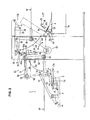
- FIG. 1 shows an example of the empty bag supply device according to the present invention used in a rotary-type bag manufacturing device 1 for manufacturing bags that are equipped spouts.
- the spout-equipped bag manufacturing device 1 includes a plurality of bag support members 3 (see FIGs. 2 and 3 ) installed on the periphery of an intermittently rotating table 2; and while the table 2 makes one rotation, the bag manufacturing device 1 receives bags 4, in each of which the bag top edge part 4a is opened and the shoulder part 4b is cut diagonally, and then holds the bags 4 horizontally on the bag support members 3.
- a spout 5 is inserted in the shoulder part 4b of each one of the bags 4, the spout 5 is adhered to the shoulder part 4b, and thus a bag 6 equipped with a diagonal spout is manufactured (see Japanese Patent Application Laid-Open (Kokai) No. 2006-224546 ).
- the bag manufacturing bag device 1 is a W- type device designed to manufacture two bags at once; and thus ten sets of bag support members 3 with each set comprising two bag supporting members 3 are provided at equal angle intervals.
- the table 2 stops ten times while it makes one rotation, and at each stop position, each one of the bag manufacturing steps for manufacturing the bag 6 equipped with a diagonal spout is performed in sequence.
- a conveyor magazine-type bag supply device 7 (only the tip part of the bag supply magazine 7a is shown) is provided, and two bags 4 are simultaneously supplied onto the bag supply members 3 via the empty bag supply device 8 of the present invention (the conveyor magazine-type bag supply device 7 and the empty bag supply device 8 are also W-type devices).
- an empty bag group is loaded with the bag mouth of each one of the bags facing the forward direction in the bag supply magazine 7a and skewed in the longitudinal direction so that the top bag is positioned forward than the other bags underneath; and two bag groups side by side are sent forward in a substantially horizontal attitude, so that the tip end of the bag of each group at the top position abuts a stopper 9 (see FIG. 2 ) that is provided positioning of the bags.
- the bags 4 positioned inside the bag supply magazine 7a are, as will be described below, supplied to the bag support members 3 by the empty bag supply device 8 with the bag mouth side and the bag bottom side directions reversed (from those of the bags which were inside the bag supply magazine) and in a substantially horizontal attitude.
- a bag holding member (comprising a movable member 11 and a stationary receiving member 12) is provided vertically with a bag support surface 3a in between.
- the movable member 11 of the bag holding member is installed so that it swings vertically on the table 2, and the receiving member 12 of the bag holding member is installed on the bag support member 3.
- the movable member 11 and the receiving member 12 respectively have gripping portions 11a and 12a at the tip ends in the radial direction.
- an air cylinder 14 When a bag 4 is placed on the bag support surface 3a, an air cylinder 14 operates so that the movable member 11 swings downward, and thus the gripping portion 11a thereof is moved down, and an area near the top edge part 4a of the bag 4 is gripped by the gripping portion 11a of the movable member 11 and the gripping portion 12a of the receiving member 12.
- Each one of the bag support members 3 is supported so as to swing on the table 2 within the vertical plane parallel to the radial direction of the table 2, and the bag support member 3 is tilted by the air cylinder 15.
- a bag positioning device 16 is provided, and positioning of the bags 4 on the bag support member 3 is made by this bag positioning device 16.
- the movable member 11 of the bag holding member is raised by the air cylinder 14 and temporarily releases the bag 4, the positioning of the bag 4 is done, the movable member 11 is then lowered and again grips the bag 4, and the bag 4 is held substantially in horizontal at a predetermined position on the bag support member 3.
- spout supply devices 17 and 18 are provided, and a device (not illustrated) for opening the bag mouth is also provided. Opening of the shoulder part 4b of each bag 4 and supply of the spout 5 (insertion of the spout into the shoulder part 4b) to each bag 4 are performed at this stop position III.
- a spout grip member 19 (see FIG. 3 ) that can open and close vertically are provided on the table 2 so as to correspond to each bag support member 3, and the spout 5 inserted in the shoulder part 4b of the bag 4 is gripped by this spout grip member 19 and held at a predetermined position.
- Sealing devices (only their heating plates 21, 22, and 23 are shown) are provided at stop positions IV to VI, and a cooling device (only its cooling plate 24 is shown) is provided at stop position VII; and thus adhesion sealing and cooling of the spout 5 and the shoulder part 4b of the bag 4 are performed at these stop positions IV to VIII.
- a testing device 25 that tests the attachment position of the spout 5 is provided at stop position VIII; and when test signals are received and the attachment of the spout 5 to the bag 4 is determined to be defective, the air cylinder 15 operates during the rotation of the table 2, the bag support member 3 is thus tilted outward and downward, and the defective bag(s) is ejected.
- bags 6 equipped with diagonal spouts are taken out by a bag transfer device (not illustrated) and transported to a bag packaging device (not illustrated).
- the empty bag supply device 8 provided between the table 2 and the conveyor magazine-type bag supply device 7 includes an empty bag take-out means that takes out the bags 4 from the bag supply magazine 7a; a first empty bag transport means that receives the bags 4 from the empty bag take-out means, transports them in a circular trajectory, and moves them into a substantially vertical attitude; and a second empty bag transport means that receives the bags 4 from the first empty bag transport means, moves the bags into a horizontal attitude, and transports the bags to and places them in the bag support members 3 of the bag manufacturing device 1.
- the empty bag take-out means of the empty bag supply device 8 is comprised of first suction-hold members 26 that are moved back and forth between the lower first receiving position and the first hand-over position which is set above the first receiving position.
- the empty bag take-out means is further comprised of a first suction-hold member moving mechanism 27 that makes the back-and-forth movement of the first suction-hold members 26 between the first receiving position and the first hand-over position.
- the first suction-hold member 26 at the first receiving position is shown by the solid lines, and it is shown by the imaginary lines (dotted lines) when it is at the first hand-over position; and the movement path of the first suction-hold member 26 is shown by the two-headed arrow A1. As seen from FIG.
- the first suction-hold member moving mechanism 27 comprises, among others, a lever 28 that supports the first suction-hold member 26 and a shaft 29 on which the lever 28 is mounted.
- the first suction-hold member 26 is connected to a switching valve and a vacuum source (not illustrated) by a vacuum pipe.
- each of the first suction-hold members 26 faces substantially horizontally downward and suction-holds the top surface near the front end in the bag-supply direction of the top or first empty bag 4 that is inside the bag supply magazine 7a and positioned abutting the stopper 9. While swinging rearward (rearward in the bag-supply direction of the empty bag 4 or to the right side in FIG. 2 ), the first suction-hold member 26 is raised and moved to the first hand-over position, so that the suction-held empty bag 4 is raised and the front end part of the bag is lifted. There are two of the first suction-hold members 26 (a left/right pair) provided for each empty bag (see the suctioned points A of each one of the bags 4 in FIG. 5 ).
- the first empty bag transport means of the empty bag supply device 8 is comprised of a grip member 31 that moves back and forth between a second receiving position and a second hand-over position that is above the second receiving position and where the grip member 31 is raised along a circular path so as to be at an upward front side of the second receiving position (or the front side in the bag-supply direction of the empty bag 4).
- the first empty bag transport means is further comprised of a grip member moving mechanism 32 that makes back-and-forth movement of the grip member 31 between the second receiving position and the second hand-over position.
- the grip member 31 at the second receiving position is shown by the imaginary lines (dotted lines), and the grip member 31 at the second hand-over position is shown by the solid lines, and the movement path of the substantially circular shape is depicted by the two-headed arrow A2.
- the grip member 31 has two grip sections 33 and 34 which have a width (horizontal direction width) that is enough for the grip sections 33 and 34 to grip two bags 4 simultaneously as shown in FIG. 3 ; and of these two grip sections 33 and 34, the grip section 34, as shown in FIG. 5 , is positioned on the back side of the bag 4 (or the rearward in the bag-supply direction of the empty bag 4) when it comes to the second hand-over position, and this grip section 34 has extended portions 34a extending in a tongue shape and are positioned so as to correspond to the middle portion of each one of the bags 4 in the bag's width direction.
- the grip section 34 is fixed to the swing lever 35 described later, and the grip section 33 is axially supported on the swing lever 35 so as to be swingable within the vertical plane along the bag-supply direction of the bag 4; and thus by the operation of the air cylinder 36 provided on the swing lever 35, the grip section 34 and the grip section 33 are opened and closed.
- the grip member moving mechanism for the grip member 31 is comprised of the swing lever 35 and a fulcrum shaft 37 axially supported in a box frame 30 in a rotatable fashion.
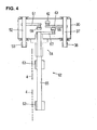
- the grip member moving mechanism is further comprised of a swing arm 38 fixed at its one end to the fulcrum shaft 37 and rotatably connected at its other end to a shaft member 40 that is fixed to the intermediate position of the swing lever 35, a link 41 that links the rear end of the swing lever 35 and a link support member 39 installed on the box frame 30, and a vertically swingable ascending-descending lever 43 of which one end is fixed to the fulcrum shaft 37 and the other end is linked to a drive source (not illustrated) via a linking member 42 (see FIG. 4 ).
- the grip member 31 When the ascending-descending lever 43 swings vertically, the grip member 31 is moved up and moved down. More specifically, when the ascending-descending lever 43 swings down, the grip sections 33 and 34 of the grip member 31, which are opened, are moved to the second receiving position; and at the second receiving position, they are closed so as to grip the front end part of the bag 4, which is lifted by the first suction-hold member 26 that has come to the first hand-over position, across the full width of the bag 4. Subsequently, the first suction-hold member 26 is vented and the bag 4 is thus released from the first suction-hold member 26.
- the suction points A of the first suction-hold member 26 are set at both sides of the extended portion 34a of the grip section 34 of the grip member 31. Accordingly, there is no mutual interference between the grip member 31 that has come to the second receiving position and the first suction-hold member 26.
- the second empty bag transport means of the empty bag supply device 8 is comprised of two second suction-hold members 44 and 45 that are moved back and forth between the upper third receiving position and the lower third hand-over position which is at the front side below the upper third receiving position (the front side in the bag-supply direction of the empty bag 4), and the second empty bag transport means further includes a second suction-hold member moving mechanism 46 that makes the back-and-forth movement of the second suction-hold members 44 and 45 between the upper third receiving position and the lower third hand-over position.
- the second suction-hold members 44 and 45 at the third receiving position are shown by the solid lines and by imaginary lines (dotted lines) when it is at the third hand-over position. Since the bag supply device 8 is a W-type device, the second suction-hold members 44 and 45 are provided as one set for each bag 4 and for a total of two sets.
- the second suction-hold members 44 and 45 of the second empty bag transport means are linked by a conduit tube 47 of a specified length; and a conduit tube 48 of the second suction-hold member 44 is fixed to an attachment stay 49 described later and, furthermore, is connected to a switching valve and a vacuum source (not illustrated) by a vacuum pipe 51.
- the second suction-hold member 44 is, as seen from FIG. 2 , positioned at an upper side, and the second suction-hold member 45 is at a lower side or below the suction-hold member 44; and at the third hand-over position, they are substantially at the same height level.
- the second suction-hold member moving mechanism 46 of the second empty bag transport means is comprised of a fulcrum shaft 52, of which one end is axially supported so as to be able to rotate horizontally on the box frame 30, and a swing arm 53, of which one end is fixed to the fulcrum shaft 52.
- the attachment stay 49 of the second suction-hold member moving mechanism 46 is rotatably provided at its base part 49a on the shaft member 53a, which is at the other end of the swing arm 53, and it extends horizontally.
- the second suction-hold member moving mechanism 46 further includes a shaft member 54 fixed to the base part 49a of the attachment stay 49, a guide block 55 slidably provided on the shaft member 54, a shaft receiving member 58 and a vertically swingable ascending-descending lever 61.
- the shaft receiving member 58 is fixed to a support member 56, which is installed on the box frame 30, and rortatably supports the shaft member 57 of the guide block 55, and the vertically swingable ascending-descending lever 61 is fixed at one end thereof to the fulcrum shaft 52 and linked at another end thereof to a drive source (not illustrated) via the linking member 59 (see FIG. 4 ).
- the attachment stay 49 makes a rotation of substantially 90° in the opposite direction with respect to the bag-supply direction with a summation of a substantially 90° rotation in the forward direction with respect to the bag-supply direction caused by the swing motion of the swing arm 53 and a substantially 180° rotation in the reverse direction described above with the shaft member 53a of the swing arm 53 at the center.
- the second suction-hold members 44 and 45 of the second empty bag transport means are provided so that, as described above, they are positioned above and below (the suction-hold member 44 being above the other suction-hold member 45) at the third receiving position, and the suction surfaces of the second suction-hold members 44 and 45 face the substantially vertical back side (back side in the bag-supply direction).
- the suction surfaces of the second suction-hold members 44 and 45 suction-hold the front-side surface of the bag 4 (forward surface of the bag with respect to the bag-supply direction), which is gripped by the grip member 31 that has come to the second hand-over position and is in a substantially vertical attitude, so that the bag 4 is suction-held at two vertical points in the width direction center part thereof (In other word, as seen from FIG. 5 , the suction surface of the upper suction-hold member 44 suction-holds the bag at B1 which is close to the bag mouth of the bag 4, and the suction surface of the lower suction-hold member 45 suction-holds the bag at B2 which is close to the center bottom of the bag).
- the grip members 31 of the first empty bag transport means are opened, and after the bags 4 are thus released from the grip members 31, the second suction-hold members 44 and 45 of the second empty bag transport means swing downward toward the third hand-over position when the attachment stay 49 swings to the downward forward side by the swing motion of the swing arm 53; and when the second suction-hold members 44 and 45 rotate about the shaft member 53a of the swing arm 53 and come to the third hand-over position, the suction surfaces of the second suction-hold members 44 and 45 take a substantially horizontal state and face down, and thus the bags 4 are also changed from a substantially vertical attitude to a substantially horizontal attitude.
- the bags 4 are placed on the bag support member 3 of the bag manufacturing device for manufacturing bags equipped spouts (see the imaginary lines (dotted lines) in FIG. 2 ), the moveable members 11 are moved down, and a portion near the top edge part 4a of each one of the bags 4 is gripped between the moveable members 11 and the receiving members 12, the second suction-hold members 44 and 45 are vented to the atmosphere to release the bags 4, and subsequently, the second suction-hold members 44 and 45 are raised back to the third receiving position.
- the empty bag supply device 8 is further provided with two suction-aid means that assures reliable suction-holing by the second suction-hold members 44 and 45.
- One suction-aid means is a suction-aid means for the second suction-hold member 44 that is positioned at the upper side at the third receiving position.
- This suction-aid means is the extended portions 34a formed on the grip section 34 that are on the back side when the grip members 31 come to the second hand-over position.
- the extended portion 34a facing the suction surface of the second suction-hold member 44 supports the rear-side surface of the bag 4. In this way, suction-holding of the bag 4 by the second suction-hold member 44 is assured.
- the other suction-aid means is a suction-aid means for the other second suction-hold member 45 which comes to a lower side at the third receiving position, and it is a suction-aid means 62 provided at a lower position of (or below) the second hand-over position of the grip member 31.
- the suction-aid means 62 is, as seen from FIG. 2 , comprised of a plate-shaped suction-aid member 63 and a suction-aid member moving mechanism 64.
- the plate-shaped suction-aid member 63 is moved by the suction-aid member moving mechanism 64 back and forth between the evacuation position, at which it takes a substantially horizontal state, and the suction-aid position, at which it takes a substantially vertical state; and the suction-aid member moving mechanism 64 makes the back-and-forth movement of the suction-aid member 63 between the evacuation position and the suction-aid position (see FIG. 4 ).
- the suction-aid member 63 at the evacuation position is shown by the imaginary lines (dotted line) and shown by the solid lines when it is at the suction-aid position, and the movement (swing) path of the suction-aid member 63 is shown by the two-headed arrow A4.
- the bag supply device 8 is a W-type device, and thus two of the suction-aid members 63 are provided in parallel.
- the suction-aid member moving mechanism 64 is comprised of a fulcrum shaft 65 rotatably provided in the box frame 30 (two suction-aid members 63 are provided) and a vertically swingable ascending-descending lever 67 of which one end is fixed to the fulcrum shaft 65 and the other end is linked to a drive source (not illustrated) via the linking member 66.
- the ascending-descending lever 67 swings vertically, the fulcrum shaft 65 rotates, and thus the suction-aid member 63 swings and moves back-and-forth between the evacuation position and the suction-aid position.
- the suction-aid members 63 avoid interference with the bags 4, which are gripped by the grip members 31, and the grip members 31 at the evacuation position; and after the grip members 31 pass through above the suction-aid members 63 and come to the second hand-over position, the suction-aid members 63 are moved to the suction-aid position.
- Each of the suction-aid members 63 that has come to the suction-aid position faces the suction surface of the second suction-hold member 45 and touches to support the rear-side surface of the bag 4 when the second suction-hold member 45 suction-holds the front-side surface of the bag 4 that is gripped by the grip member 31 and in a substantially vertical attitude (see suction point B2 in FIG. 5 ). In this way, the suction-holding of the bag 4 by the second suction-hold member 45 is assured.
- empty bag supply device 8 is only one example of the present invention, and it is possible to provide modifications as described below within the technical scope of the present invention.
Landscapes
- Engineering & Computer Science (AREA)
- Mechanical Engineering (AREA)
- Supplying Of Containers To The Packaging Station (AREA)
- Making Paper Articles (AREA)
Applications Claiming Priority (1)
| Application Number | Priority Date | Filing Date | Title |
|---|---|---|---|
| JP2008085095A JP5197093B2 (ja) | 2008-03-28 | 2008-03-28 | 空袋供給方法及び空袋供給装置 |
Publications (2)
| Publication Number | Publication Date |
|---|---|
| EP2105382A1 true EP2105382A1 (de) | 2009-09-30 |
| EP2105382B1 EP2105382B1 (de) | 2011-05-11 |
Family
ID=40796966
Family Applications (1)
| Application Number | Title | Priority Date | Filing Date |
|---|---|---|---|
| EP09004564A Not-in-force EP2105382B1 (de) | 2008-03-28 | 2009-03-30 | Verfahren zur Bereitstellung leerer Säcke und Vorrichtung zur Bereitstellung leerer Säcke |
Country Status (5)
| Country | Link |
|---|---|
| US (1) | US20090241475A1 (de) |
| EP (1) | EP2105382B1 (de) |
| JP (1) | JP5197093B2 (de) |
| AT (1) | ATE508950T1 (de) |
| ES (1) | ES2363488T3 (de) |
Cited By (1)
| Publication number | Priority date | Publication date | Assignee | Title |
|---|---|---|---|---|
| CN103723308A (zh) * | 2012-10-12 | 2014-04-16 | 东洋自动机株式会社 | 装袋包装中的袋口开口方法及装置 |
Families Citing this family (4)
| Publication number | Priority date | Publication date | Assignee | Title |
|---|---|---|---|---|
| US20130019571A1 (en) * | 2011-07-20 | 2013-01-24 | OYSTAR North America | Methods and apparatus for high-speed pouch-filling |
| DE102011113879A1 (de) * | 2011-09-22 | 2013-03-28 | Haver & Boecker Ohg | Vorrichtung und Verfahren zum Bearbeiten von Sackstapeln von Offensäcken |
| JP6315462B2 (ja) * | 2014-07-17 | 2018-04-25 | 東洋自動機株式会社 | 袋のスパウト取付部を開口する方法及び装置 |
| CN119929269A (zh) * | 2025-03-19 | 2025-05-06 | 成都潇智源裕科技有限公司 | 一种包装机 |
Citations (5)
| Publication number | Priority date | Publication date | Assignee | Title |
|---|---|---|---|---|
| JP2588135B2 (ja) | 1994-03-01 | 1997-03-05 | 栄一 石渡 | 座席用座蒲団 |
| JP3084539B2 (ja) | 1992-04-30 | 2000-09-04 | 東洋自動機株式会社 | 自動包装機の袋取出し装置 |
| EP1447331A2 (de) * | 2003-02-17 | 2004-08-18 | Toyo Jidoki Co., Ltd. | Maschinen zum Herstellen, Befüllen und Siegeln von Beuteln |
| JP2006036325A (ja) | 2004-07-29 | 2006-02-09 | General Packer Co Ltd | 包装機の包装袋供給装置 |
| JP2006224546A (ja) | 2005-02-18 | 2006-08-31 | Toyo Jidoki Co Ltd | スパウト付き袋の製造方法及び装置 |
Family Cites Families (10)
| Publication number | Priority date | Publication date | Assignee | Title |
|---|---|---|---|---|
| IT995630B (it) * | 1973-10-05 | 1975-11-20 | Buzzi R | Macchina per riempire e cucire automaticamente sacchi |
| US4545184A (en) * | 1983-06-03 | 1985-10-08 | Shigeo Akiyama | Apparatus for supplying bags of pliable or easily flexible nature |
| AT404117B (de) * | 1988-12-02 | 1998-08-25 | Binder Co Ag | Einrichtung zum zuführen eines vereinzelten sackes |
| US5337541A (en) * | 1991-01-26 | 1994-08-16 | Buehler Ag | Method for the automatic supply of bags and bag hanging apparatus |
| US5201166A (en) * | 1992-03-23 | 1993-04-13 | Johnsen Machine Company Ltd. | Bag handling machine |
| JP3622120B2 (ja) * | 1995-02-16 | 2005-02-23 | 株式会社Kitano | ディスクケースの装着移載方法およびその装置 |
| JP2003137219A (ja) * | 2001-11-01 | 2003-05-14 | Toyo Jidoki Co Ltd | コンベアマガジン式袋供給装置 |
| DE60237544D1 (de) * | 2001-12-21 | 2010-10-14 | Sealed Air New Zealand | Vorrichtung und verfahren zum öffnen von packungen |
| JP4530882B2 (ja) * | 2005-03-04 | 2010-08-25 | 東洋自動機株式会社 | スパウト付き袋の製造方法 |
| JP4753780B2 (ja) * | 2006-04-27 | 2011-08-24 | 東洋自動機株式会社 | 包装機の給袋装置 |
-
2008
- 2008-03-28 JP JP2008085095A patent/JP5197093B2/ja active Active
-
2009
- 2009-03-27 US US12/383,724 patent/US20090241475A1/en not_active Abandoned
- 2009-03-30 AT AT09004564T patent/ATE508950T1/de not_active IP Right Cessation
- 2009-03-30 ES ES09004564T patent/ES2363488T3/es active Active
- 2009-03-30 EP EP09004564A patent/EP2105382B1/de not_active Not-in-force
Patent Citations (5)
| Publication number | Priority date | Publication date | Assignee | Title |
|---|---|---|---|---|
| JP3084539B2 (ja) | 1992-04-30 | 2000-09-04 | 東洋自動機株式会社 | 自動包装機の袋取出し装置 |
| JP2588135B2 (ja) | 1994-03-01 | 1997-03-05 | 栄一 石渡 | 座席用座蒲団 |
| EP1447331A2 (de) * | 2003-02-17 | 2004-08-18 | Toyo Jidoki Co., Ltd. | Maschinen zum Herstellen, Befüllen und Siegeln von Beuteln |
| JP2006036325A (ja) | 2004-07-29 | 2006-02-09 | General Packer Co Ltd | 包装機の包装袋供給装置 |
| JP2006224546A (ja) | 2005-02-18 | 2006-08-31 | Toyo Jidoki Co Ltd | スパウト付き袋の製造方法及び装置 |
Cited By (2)
| Publication number | Priority date | Publication date | Assignee | Title |
|---|---|---|---|---|
| CN103723308A (zh) * | 2012-10-12 | 2014-04-16 | 东洋自动机株式会社 | 装袋包装中的袋口开口方法及装置 |
| EP2719630A1 (de) * | 2012-10-12 | 2014-04-16 | Toyo Jidoki Co., Ltd. | Beutelöffnungsverfahren und -vorrichtung zur Verwendung bei der Beutelbefüllung und -verpackung |
Also Published As
| Publication number | Publication date |
|---|---|
| JP5197093B2 (ja) | 2013-05-15 |
| ES2363488T3 (es) | 2011-08-05 |
| JP2009234132A (ja) | 2009-10-15 |
| US20090241475A1 (en) | 2009-10-01 |
| ATE508950T1 (de) | 2011-05-15 |
| EP2105382B1 (de) | 2011-05-11 |
Similar Documents
| Publication | Publication Date | Title |
|---|---|---|
| EP2149499B1 (de) | Verfahren und Vorrichtung zum Zuführen leerer Beuteln | |
| US8720667B2 (en) | Product bag unloading apparatus | |
| US4473247A (en) | Component mounting apparatus | |
| JP5064129B2 (ja) | スパウト装着装置 | |
| EP2105382B1 (de) | Verfahren zur Bereitstellung leerer Säcke und Vorrichtung zur Bereitstellung leerer Säcke | |
| JP3917307B2 (ja) | 特に、ソフトフィルムパックを処理する装置 | |
| CN103662204A (zh) | 带有管口的袋的制造方法及装置 | |
| EP1693186B1 (de) | Verfahren und Vorrichtung zum Herstellen eines Beutels mit Ausgusstüllen | |
| JP2015168456A (ja) | 袋の供給方法及び袋供給装置 | |
| JP2551295B2 (ja) | 段ボール箱の自動開箱、物品取り出し、折畳方法及び装置 | |
| US20060199716A1 (en) | Method of manufacturing a bag equipped with a spout | |
| CN220865878U (zh) | 自动包装生产线 | |
| EP1335855B1 (de) | Maschine zum verpacken von gegenständen, insbesondere cds, dvds und dergleichen, in behältern | |
| JP2009023280A (ja) | スパウト装着装置 | |
| JP2020117310A (ja) | 袋取出方法及び袋取出装置 | |
| JP7409924B2 (ja) | 袋供給方法及び袋供給装置 | |
| CN116176941A (zh) | 堆叠翻转组件及自动化包装设备 | |
| JP5112769B2 (ja) | スパウト装着装置 | |
| JP3586017B2 (ja) | 容器切出し装置 | |
| JP3556208B2 (ja) | 袋類供給装置 | |
| JP4120060B2 (ja) | カートン取出し装置 | |
| CN219616162U (zh) | 一种电池片分选机构 | |
| JP7746119B2 (ja) | 搬送システム | |
| JP3568519B2 (ja) | 包装機の給袋装置 | |
| JP2008093836A (ja) | スパウト装着装置 |
Legal Events
| Date | Code | Title | Description |
|---|---|---|---|
| PUAI | Public reference made under article 153(3) epc to a published international application that has entered the european phase |
Free format text: ORIGINAL CODE: 0009012 |
|
| AK | Designated contracting states |
Kind code of ref document: A1 Designated state(s): AT BE BG CH CY CZ DE DK EE ES FI FR GB GR HR HU IE IS IT LI LT LU LV MC MK MT NL NO PL PT RO SE SI SK TR |
|
| AX | Request for extension of the european patent |
Extension state: AL BA RS |
|
| 17P | Request for examination filed |
Effective date: 20100121 |
|
| AKX | Designation fees paid |
Designated state(s): AT BE BG CH CY CZ DE DK EE ES FI FR GB GR HR HU IE IS IT LI LT LU LV MC MK MT NL NO PL PT RO SE SI SK TR |
|
| GRAP | Despatch of communication of intention to grant a patent |
Free format text: ORIGINAL CODE: EPIDOSNIGR1 |
|
| GRAS | Grant fee paid |
Free format text: ORIGINAL CODE: EPIDOSNIGR3 |
|
| GRAA | (expected) grant |
Free format text: ORIGINAL CODE: 0009210 |
|
| AK | Designated contracting states |
Kind code of ref document: B1 Designated state(s): AT BE BG CH CY CZ DE DK EE ES FI FR GB GR HR HU IE IS IT LI LT LU LV MC MK MT NL NO PL PT RO SE SI SK TR |
|
| REG | Reference to a national code |
Ref country code: GB Ref legal event code: FG4D |
|
| REG | Reference to a national code |
Ref country code: CH Ref legal event code: EP |
|
| REG | Reference to a national code |
Ref country code: IE Ref legal event code: FG4D |
|
| REG | Reference to a national code |
Ref country code: DE Ref legal event code: R096 Ref document number: 602009001251 Country of ref document: DE Effective date: 20110622 |
|
| REG | Reference to a national code |
Ref country code: ES Ref legal event code: FG2A Ref document number: 2363488 Country of ref document: ES Kind code of ref document: T3 Effective date: 20110805 |
|
| REG | Reference to a national code |
Ref country code: NL Ref legal event code: VDEP Effective date: 20110511 |
|
| PG25 | Lapsed in a contracting state [announced via postgrant information from national office to epo] |
Ref country code: NO Free format text: LAPSE BECAUSE OF FAILURE TO SUBMIT A TRANSLATION OF THE DESCRIPTION OR TO PAY THE FEE WITHIN THE PRESCRIBED TIME-LIMIT Effective date: 20110811 Ref country code: LT Free format text: LAPSE BECAUSE OF FAILURE TO SUBMIT A TRANSLATION OF THE DESCRIPTION OR TO PAY THE FEE WITHIN THE PRESCRIBED TIME-LIMIT Effective date: 20110511 Ref country code: PT Free format text: LAPSE BECAUSE OF FAILURE TO SUBMIT A TRANSLATION OF THE DESCRIPTION OR TO PAY THE FEE WITHIN THE PRESCRIBED TIME-LIMIT Effective date: 20110912 Ref country code: SE Free format text: LAPSE BECAUSE OF FAILURE TO SUBMIT A TRANSLATION OF THE DESCRIPTION OR TO PAY THE FEE WITHIN THE PRESCRIBED TIME-LIMIT Effective date: 20110511 |
|
| PG25 | Lapsed in a contracting state [announced via postgrant information from national office to epo] |
Ref country code: LV Free format text: LAPSE BECAUSE OF FAILURE TO SUBMIT A TRANSLATION OF THE DESCRIPTION OR TO PAY THE FEE WITHIN THE PRESCRIBED TIME-LIMIT Effective date: 20110511 Ref country code: FI Free format text: LAPSE BECAUSE OF FAILURE TO SUBMIT A TRANSLATION OF THE DESCRIPTION OR TO PAY THE FEE WITHIN THE PRESCRIBED TIME-LIMIT Effective date: 20110511 Ref country code: BE Free format text: LAPSE BECAUSE OF FAILURE TO SUBMIT A TRANSLATION OF THE DESCRIPTION OR TO PAY THE FEE WITHIN THE PRESCRIBED TIME-LIMIT Effective date: 20110511 Ref country code: SI Free format text: LAPSE BECAUSE OF FAILURE TO SUBMIT A TRANSLATION OF THE DESCRIPTION OR TO PAY THE FEE WITHIN THE PRESCRIBED TIME-LIMIT Effective date: 20110511 Ref country code: IS Free format text: LAPSE BECAUSE OF FAILURE TO SUBMIT A TRANSLATION OF THE DESCRIPTION OR TO PAY THE FEE WITHIN THE PRESCRIBED TIME-LIMIT Effective date: 20110911 Ref country code: GR Free format text: LAPSE BECAUSE OF FAILURE TO SUBMIT A TRANSLATION OF THE DESCRIPTION OR TO PAY THE FEE WITHIN THE PRESCRIBED TIME-LIMIT Effective date: 20110812 Ref country code: AT Free format text: LAPSE BECAUSE OF FAILURE TO SUBMIT A TRANSLATION OF THE DESCRIPTION OR TO PAY THE FEE WITHIN THE PRESCRIBED TIME-LIMIT Effective date: 20110511 Ref country code: CY Free format text: LAPSE BECAUSE OF FAILURE TO SUBMIT A TRANSLATION OF THE DESCRIPTION OR TO PAY THE FEE WITHIN THE PRESCRIBED TIME-LIMIT Effective date: 20110511 |
|
| PG25 | Lapsed in a contracting state [announced via postgrant information from national office to epo] |
Ref country code: NL Free format text: LAPSE BECAUSE OF FAILURE TO SUBMIT A TRANSLATION OF THE DESCRIPTION OR TO PAY THE FEE WITHIN THE PRESCRIBED TIME-LIMIT Effective date: 20110511 |
|
| PG25 | Lapsed in a contracting state [announced via postgrant information from national office to epo] |
Ref country code: CZ Free format text: LAPSE BECAUSE OF FAILURE TO SUBMIT A TRANSLATION OF THE DESCRIPTION OR TO PAY THE FEE WITHIN THE PRESCRIBED TIME-LIMIT Effective date: 20110511 Ref country code: EE Free format text: LAPSE BECAUSE OF FAILURE TO SUBMIT A TRANSLATION OF THE DESCRIPTION OR TO PAY THE FEE WITHIN THE PRESCRIBED TIME-LIMIT Effective date: 20110511 |
|
| PG25 | Lapsed in a contracting state [announced via postgrant information from national office to epo] |
Ref country code: PL Free format text: LAPSE BECAUSE OF FAILURE TO SUBMIT A TRANSLATION OF THE DESCRIPTION OR TO PAY THE FEE WITHIN THE PRESCRIBED TIME-LIMIT Effective date: 20110511 Ref country code: RO Free format text: LAPSE BECAUSE OF FAILURE TO SUBMIT A TRANSLATION OF THE DESCRIPTION OR TO PAY THE FEE WITHIN THE PRESCRIBED TIME-LIMIT Effective date: 20110511 Ref country code: SK Free format text: LAPSE BECAUSE OF FAILURE TO SUBMIT A TRANSLATION OF THE DESCRIPTION OR TO PAY THE FEE WITHIN THE PRESCRIBED TIME-LIMIT Effective date: 20110511 Ref country code: DK Free format text: LAPSE BECAUSE OF FAILURE TO SUBMIT A TRANSLATION OF THE DESCRIPTION OR TO PAY THE FEE WITHIN THE PRESCRIBED TIME-LIMIT Effective date: 20110511 |
|
| PLBE | No opposition filed within time limit |
Free format text: ORIGINAL CODE: 0009261 |
|
| STAA | Information on the status of an ep patent application or granted ep patent |
Free format text: STATUS: NO OPPOSITION FILED WITHIN TIME LIMIT |
|
| 26N | No opposition filed |
Effective date: 20120214 |
|
| PG25 | Lapsed in a contracting state [announced via postgrant information from national office to epo] |
Ref country code: HR Free format text: LAPSE BECAUSE OF FAILURE TO SUBMIT A TRANSLATION OF THE DESCRIPTION OR TO PAY THE FEE WITHIN THE PRESCRIBED TIME-LIMIT Effective date: 20111123 |
|
| REG | Reference to a national code |
Ref country code: DE Ref legal event code: R097 Ref document number: 602009001251 Country of ref document: DE Effective date: 20120214 |
|
| PG25 | Lapsed in a contracting state [announced via postgrant information from national office to epo] |
Ref country code: MC Free format text: LAPSE BECAUSE OF NON-PAYMENT OF DUE FEES Effective date: 20120331 |
|
| REG | Reference to a national code |
Ref country code: IE Ref legal event code: MM4A |
|
| PG25 | Lapsed in a contracting state [announced via postgrant information from national office to epo] |
Ref country code: IE Free format text: LAPSE BECAUSE OF NON-PAYMENT OF DUE FEES Effective date: 20120330 |
|
| PG25 | Lapsed in a contracting state [announced via postgrant information from national office to epo] |
Ref country code: MK Free format text: LAPSE BECAUSE OF FAILURE TO SUBMIT A TRANSLATION OF THE DESCRIPTION OR TO PAY THE FEE WITHIN THE PRESCRIBED TIME-LIMIT Effective date: 20110511 |
|
| PG25 | Lapsed in a contracting state [announced via postgrant information from national office to epo] |
Ref country code: BG Free format text: LAPSE BECAUSE OF FAILURE TO SUBMIT A TRANSLATION OF THE DESCRIPTION OR TO PAY THE FEE WITHIN THE PRESCRIBED TIME-LIMIT Effective date: 20110811 |
|
| PG25 | Lapsed in a contracting state [announced via postgrant information from national office to epo] |
Ref country code: MT Free format text: LAPSE BECAUSE OF FAILURE TO SUBMIT A TRANSLATION OF THE DESCRIPTION OR TO PAY THE FEE WITHIN THE PRESCRIBED TIME-LIMIT Effective date: 20110511 |
|
| REG | Reference to a national code |
Ref country code: CH Ref legal event code: PL |
|
| PG25 | Lapsed in a contracting state [announced via postgrant information from national office to epo] |
Ref country code: HR Free format text: LAPSE BECAUSE OF FAILURE TO SUBMIT A TRANSLATION OF THE DESCRIPTION OR TO PAY THE FEE WITHIN THE PRESCRIBED TIME-LIMIT Effective date: 20110511 |
|
| PG25 | Lapsed in a contracting state [announced via postgrant information from national office to epo] |
Ref country code: CH Free format text: LAPSE BECAUSE OF NON-PAYMENT OF DUE FEES Effective date: 20130331 Ref country code: LI Free format text: LAPSE BECAUSE OF NON-PAYMENT OF DUE FEES Effective date: 20130331 |
|
| PG25 | Lapsed in a contracting state [announced via postgrant information from national office to epo] |
Ref country code: TR Free format text: LAPSE BECAUSE OF FAILURE TO SUBMIT A TRANSLATION OF THE DESCRIPTION OR TO PAY THE FEE WITHIN THE PRESCRIBED TIME-LIMIT Effective date: 20110511 |
|
| PG25 | Lapsed in a contracting state [announced via postgrant information from national office to epo] |
Ref country code: LU Free format text: LAPSE BECAUSE OF NON-PAYMENT OF DUE FEES Effective date: 20120330 |
|
| PG25 | Lapsed in a contracting state [announced via postgrant information from national office to epo] |
Ref country code: HU Free format text: LAPSE BECAUSE OF FAILURE TO SUBMIT A TRANSLATION OF THE DESCRIPTION OR TO PAY THE FEE WITHIN THE PRESCRIBED TIME-LIMIT Effective date: 20090330 |
|
| REG | Reference to a national code |
Ref country code: FR Ref legal event code: PLFP Year of fee payment: 8 |
|
| REG | Reference to a national code |
Ref country code: FR Ref legal event code: PLFP Year of fee payment: 9 |
|
| REG | Reference to a national code |
Ref country code: DE Ref legal event code: R082 Ref document number: 602009001251 Country of ref document: DE Representative=s name: KEIL & SCHAAFHAUSEN PATENTANWAELTE PARTGMBB, DE Ref country code: DE Ref legal event code: R082 Ref document number: 602009001251 Country of ref document: DE Representative=s name: KEIL & SCHAAFHAUSEN PATENT- UND RECHTSANWAELTE, DE |
|
| REG | Reference to a national code |
Ref country code: FR Ref legal event code: PLFP Year of fee payment: 10 |
|
| PGFP | Annual fee paid to national office [announced via postgrant information from national office to epo] |
Ref country code: FR Payment date: 20210323 Year of fee payment: 13 Ref country code: IT Payment date: 20210329 Year of fee payment: 13 |
|
| PGFP | Annual fee paid to national office [announced via postgrant information from national office to epo] |
Ref country code: DE Payment date: 20210319 Year of fee payment: 13 Ref country code: GB Payment date: 20210324 Year of fee payment: 13 |
|
| PGFP | Annual fee paid to national office [announced via postgrant information from national office to epo] |
Ref country code: ES Payment date: 20210525 Year of fee payment: 13 |
|
| REG | Reference to a national code |
Ref country code: DE Ref legal event code: R119 Ref document number: 602009001251 Country of ref document: DE |
|
| GBPC | Gb: european patent ceased through non-payment of renewal fee |
Effective date: 20220330 |
|
| PG25 | Lapsed in a contracting state [announced via postgrant information from national office to epo] |
Ref country code: GB Free format text: LAPSE BECAUSE OF NON-PAYMENT OF DUE FEES Effective date: 20220330 Ref country code: FR Free format text: LAPSE BECAUSE OF NON-PAYMENT OF DUE FEES Effective date: 20220331 Ref country code: DE Free format text: LAPSE BECAUSE OF NON-PAYMENT OF DUE FEES Effective date: 20221001 |
|
| REG | Reference to a national code |
Ref country code: ES Ref legal event code: FD2A Effective date: 20230509 |
|
| PG25 | Lapsed in a contracting state [announced via postgrant information from national office to epo] |
Ref country code: IT Free format text: LAPSE BECAUSE OF NON-PAYMENT OF DUE FEES Effective date: 20220330 |
|
| PG25 | Lapsed in a contracting state [announced via postgrant information from national office to epo] |
Ref country code: ES Free format text: LAPSE BECAUSE OF NON-PAYMENT OF DUE FEES Effective date: 20220331 |