EP2105405A1 - Füllvorrichtung für Boiler und Füllvorgang, der mit der Vorrichtung ausgeführt wird - Google Patents
Füllvorrichtung für Boiler und Füllvorgang, der mit der Vorrichtung ausgeführt wird Download PDFInfo
- Publication number
- EP2105405A1 EP2105405A1 EP08425191A EP08425191A EP2105405A1 EP 2105405 A1 EP2105405 A1 EP 2105405A1 EP 08425191 A EP08425191 A EP 08425191A EP 08425191 A EP08425191 A EP 08425191A EP 2105405 A1 EP2105405 A1 EP 2105405A1
- Authority
- EP
- European Patent Office
- Prior art keywords
- boiler
- outlet mouth
- mouth
- water
- outlet
- Prior art date
- Legal status (The legal status is an assumption and is not a legal conclusion. Google has not performed a legal analysis and makes no representation as to the accuracy of the status listed.)
- Withdrawn
Links
- 238000005429 filling process Methods 0.000 title claims description 3
- XLYOFNOQVPJJNP-UHFFFAOYSA-N water Substances O XLYOFNOQVPJJNP-UHFFFAOYSA-N 0.000 claims abstract description 53
- 238000000034 method Methods 0.000 claims abstract description 9
- 238000003780 insertion Methods 0.000 claims abstract description 3
- 230000037431 insertion Effects 0.000 claims abstract description 3
- 238000001816 cooling Methods 0.000 claims description 3
- 238000009833 condensation Methods 0.000 claims description 2
- 230000005494 condensation Effects 0.000 claims description 2
- 238000000605 extraction Methods 0.000 claims 2
- 230000000977 initiatory effect Effects 0.000 claims 1
- 230000000694 effects Effects 0.000 description 3
- 239000000498 cooling water Substances 0.000 description 1
- 230000008878 coupling Effects 0.000 description 1
- 238000010168 coupling process Methods 0.000 description 1
- 238000005859 coupling reaction Methods 0.000 description 1
- 238000009499 grossing Methods 0.000 description 1
- 235000000396 iron Nutrition 0.000 description 1
- 238000010409 ironing Methods 0.000 description 1
- 238000004519 manufacturing process Methods 0.000 description 1
- 239000007769 metal material Substances 0.000 description 1
- 238000005507 spraying Methods 0.000 description 1
- 239000000126 substance Substances 0.000 description 1
- 238000006467 substitution reaction Methods 0.000 description 1
Images
Classifications
-
- B—PERFORMING OPERATIONS; TRANSPORTING
- B67—OPENING, CLOSING OR CLEANING BOTTLES, JARS OR SIMILAR CONTAINERS; LIQUID HANDLING
- B67C—CLEANING, FILLING WITH LIQUIDS OR SEMILIQUIDS, OR EMPTYING, OF BOTTLES, JARS, CANS, CASKS, BARRELS, OR SIMILAR CONTAINERS, NOT OTHERWISE PROVIDED FOR; FUNNELS
- B67C11/00—Funnels, e.g. for liquids
-
- B—PERFORMING OPERATIONS; TRANSPORTING
- B67—OPENING, CLOSING OR CLEANING BOTTLES, JARS OR SIMILAR CONTAINERS; LIQUID HANDLING
- B67C—CLEANING, FILLING WITH LIQUIDS OR SEMILIQUIDS, OR EMPTYING, OF BOTTLES, JARS, CANS, CASKS, BARRELS, OR SIMILAR CONTAINERS, NOT OTHERWISE PROVIDED FOR; FUNNELS
- B67C11/00—Funnels, e.g. for liquids
- B67C11/02—Funnels, e.g. for liquids without discharge valves
-
- B—PERFORMING OPERATIONS; TRANSPORTING
- B67—OPENING, CLOSING OR CLEANING BOTTLES, JARS OR SIMILAR CONTAINERS; LIQUID HANDLING
- B67C—CLEANING, FILLING WITH LIQUIDS OR SEMILIQUIDS, OR EMPTYING, OF BOTTLES, JARS, CANS, CASKS, BARRELS, OR SIMILAR CONTAINERS, NOT OTHERWISE PROVIDED FOR; FUNNELS
- B67C11/00—Funnels, e.g. for liquids
- B67C2011/40—Funnels, e.g. for liquids comprising level indicating means
Definitions
- the invention relates to a filling device for boilers and a filling process performed using the device.
- the process and the device are used for filling boilers for production of steam which overheat on finishing the water present inside them.
- the device and process are particularly applicable to boilers of small electrical domestic appliances, such as smoothing irons, steam cleaners and the like; the use of the device and process of the invention is however possible and advantageous in all cases in which heated water-filled tanks are used, such as, for example, car radiators and the like, which exhibit the same problems that will be described herein below.
- tanks such as boilers in small domestic appliances destined to produce steam, but also cooling water tanks such as for example car radiators, run dry of water.
- the walls of the tanks heat up and it is therefore necessary to block the heat source and re-fill the tank with a quantity of water.
- a further drawback which obtains during the filling of boilers and the like is due to the fact that, as the inlet mouth is small and there is often the necessity of using funnels or the like for the filling operation, which further reduce the visibility inside the tank to be filled, is that often an excessive quantity of water is added which, when the tank is full, exits from the tank and wets the surrounding zone.
- the main aim of the present invention is to obviate the above-described drawbacks by providing a filling device which enables still-hot boilers or tanks to be filled up without causing drawbacks, and avoiding the spilling of water due to an over-filling of the tank.
- An advantage of the invention is that it is extremely economical to make and very easy to use for the purpose of the present invention, even for inexpert people.
- a further advantage of the invention is that it is not large and enables the process to be performed in any environment.
- the filling device of the invention is used for filling boilers, tanks and the like.
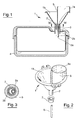
- the device comprises a funnel body 1 which is open towards the outside and is provided with an outlet mouth 2, which is sealedly inserted on an inlet mouth 3 provided on the boiler 4.
- the funnel body 1 preferably exhibits a truncoconical shape with a conicity facing the outlet mouth 2 thereof; briefly, then, the body 1, as can be seen in a possible and preferably embodiment illustrated in the figures, is a sort of funnel with constructional characteristics which will be better described herein below.
- the funnel body 1 is subdivided into a first part 1a and a second part 1b, each of which is open externalwise and exhibits an outlet mouth, respectively 2a and 2b, the outlet mouths 2a and 2b of the two parts of the funnel body 1 being afforded internally of the outlet mouth 2 of the funnel body 1 itself.
- the first part 1a is delimited by a cylindrical surface 5 which is afforded internally of the funnel body 1.
- the two parts into which the funnel body 1 is subdivided do not communicate with one another if not, obviously, via their externalwards openings and the outlet mouths thereof; in other words, there is no direct water passage from the first to the second part, and vice versa, of the funnel body 1.
- the outlet mouth 2a of the first part 1a of the funnel body 1 exhibits a section that is smaller that the outlet mouth 2b of the second part 1b of the funnel body. Further, the externalwards opening of the first part 1a of the funnel is higher up, with respect to the inlet mouth 3 of the boiler 4, than the height of the externalwards opening of the second part of the funnel body 1.
- the device of the invention further comprises a hollow elongate body 6, normally a small tube of plastic or metal material, an end of which is inserted solidly into the outlet mouth 1a of the first part of the funnel body 1, while another end thereof, when the funnel body 1 is inserted in the inlet mouth 3 of the boiler 4, opens internally of the boiler itself at a predetermined height which depends on the desired maximum level of the water in the tank when the tank is considered to be full.
- a hollow elongate body 6 normally a small tube of plastic or metal material, an end of which is inserted solidly into the outlet mouth 1a of the first part of the funnel body 1, while another end thereof, when the funnel body 1 is inserted in the inlet mouth 3 of the boiler 4, opens internally of the boiler itself at a predetermined height which depends on the desired maximum level of the water in the tank when the tank is considered to be full.
- the elongate body 6 which can be of various lengths, has the function of "displacing" the outlet mouth 2a of the first part 1a of the funnel body 1 towards the inside of the tank, such as to regulate, in a way which will be more fully described herein below and with the simple substitution of the body 6, or with a change in the length thereof, the maximum height of the water head in the tank.
- a seal 7 is also included, which is interposed between the outlet mouth 2 of the funnel body 1 and the inlet mouth 3 of the boiler, the function of which is to ensure a seal between the outlet mouth 2 of the funnel body 1 and the inlet mouth 3 of the boiler.
- the seal 7 exhibits an internal hole of equal diameter to the external diameter of the outlet mouth 2 of the funnel body 1 and an external diameter which has at least a section of diameter which is equal to the diameter of the inlet mouth 3 of the boiler.
- the seal 7 is also provided with a front seal surface which rests on the external bottom of the funnel body 1.
- the figures illustrate an externally-cylindrical seal, i.e. having all the external sections equal to the section of the inlet mouth 3 of the boiler; this type of seal is suitable only for boilers having an inlet mouth of a diameter equal to the external diameter of the seal. It is however possible to make a seal having an external truncoconical shape, i.e. having external diameter sections that decrease in a downwards direction; in this way the device can be adapted to boilers having different inlet mouth dimensions.
- the first and a second inlet mouths are inserted on the inlet mouth of the boiler inlet: with the present device, this stage is done by inserting the outlet mouth 2 of the device, which internally comprises the first and the second outlet mouths 2a and 2b, which also function as the two introduction mouths of the water into the boiler.
- a small quantity of water is then poured into the boiler, through the first outlet mouth 2a, above which outlet mouth 2a a predetermined water head is located, represented by water which has been poured into the first zone 1a of the device.
- the section of the outlet mouth 2a is rather small, and the water poured into the zone 1a enters in small doses into the boiler. Note that there is no fixed rule as to the shapes and sizes of the components of the device, in particular the outlet mouth 2a, but they must be such as to enable the described operations to take place; as for the outlet mouth 2a, a circular section having a diameter of a few millimetres is preferred, such as to enable introduction of water in small quantities.
- the water entering the boiler comes into contact with the overheated internal walls of the boiler, at least partially vaporises and begins to cool the boiler walls; during this stage there is a contemporaneous exit of the steam produced internally of the boiler through the second outlet mouth 2b, i.e. the outlet mouth 2b of the second zone 1b of the funnel body 1, which is free towards the outside.
- the water is introduced into the boiler through the second outlet mouth 2b, with a predetermined water head represented by the water which is poured into the second part 1b of the funnel body 1; in this way the second outlet mouth 2b is closed and exit of the gassy phase and an entry of air into the tank is at least temporarily closed (note that the first mouth 2a is closed by the water head present in the first zone 1a).
- the water which enters the boiler in a considerable quantity given the greater surface area of the outlet mouth 2b, causes, apart from a further cooling of the internal walls of the boiler, the condensation of at least part of the steam contained in the boiler and the consequent creation of a degree of depression internally of the boiler itself.
- This internal depression in the boiler causes aspiration of the water heads present on the first and second inlet mouths, i.e. the aspiration of all the water in the first and second zones 1a, 1b of the funnel body 1, without causing any spraying of water towards the outside environment.
- the first outlet mouth 2a is closed by the water itself and blocks, so the gassy phase no longer exits through the first mouth; the pressure inside the boiler increases and water inlet from the second outlet mouth 2b is stopped. The user thus receives the indication of the fact that the water in the boiler has reached the desired level.
- the inlet mouths are removed from the inlet of the boiler, i.e. the seal between the filling device and the inlet mouth of the boiler is removed, such that the inside of the boiler re-establishes connection with the outside, causing inlet of air into the boiler and the consequent fall, internally of the boiler, of the water still present in the inlet mouths, i.e. in particular in the zone 1b of the funnel body 1.
- the risk of overflowing of water due to excessive filling is obviated.
- the inlet mouths are then completely removed from the inlet mouths of the boiler, i.e. the filling device is completely removed, and a cap of usual type (not illustrated in the figures of the drawings) is used to close the inlet mouth of the boiler, which can then return to its normal operation.
Landscapes
- Filling Of Jars Or Cans And Processes For Cleaning And Sealing Jars (AREA)
Priority Applications (1)
| Application Number | Priority Date | Filing Date | Title |
|---|---|---|---|
| EP08425191A EP2105405A1 (de) | 2008-03-25 | 2008-03-25 | Füllvorrichtung für Boiler und Füllvorgang, der mit der Vorrichtung ausgeführt wird |
Applications Claiming Priority (1)
| Application Number | Priority Date | Filing Date | Title |
|---|---|---|---|
| EP08425191A EP2105405A1 (de) | 2008-03-25 | 2008-03-25 | Füllvorrichtung für Boiler und Füllvorgang, der mit der Vorrichtung ausgeführt wird |
Publications (1)
| Publication Number | Publication Date |
|---|---|
| EP2105405A1 true EP2105405A1 (de) | 2009-09-30 |
Family
ID=39672591
Family Applications (1)
| Application Number | Title | Priority Date | Filing Date |
|---|---|---|---|
| EP08425191A Withdrawn EP2105405A1 (de) | 2008-03-25 | 2008-03-25 | Füllvorrichtung für Boiler und Füllvorgang, der mit der Vorrichtung ausgeführt wird |
Country Status (1)
| Country | Link |
|---|---|
| EP (1) | EP2105405A1 (de) |
Cited By (3)
| Publication number | Priority date | Publication date | Assignee | Title |
|---|---|---|---|---|
| GB2484532A (en) * | 2010-10-15 | 2012-04-18 | Spectrum Brands Uk Ltd | Iron with storage space |
| EP2762634B1 (de) * | 2013-02-01 | 2017-08-30 | Panasonic Corporation | Wäschetrockner |
| CN107285264A (zh) * | 2017-07-18 | 2017-10-24 | 无锡菲兰爱尔空气质量技术有限公司 | 医用废液收集机构 |
Citations (9)
| Publication number | Priority date | Publication date | Assignee | Title |
|---|---|---|---|---|
| FR367273A (fr) * | 1906-06-19 | 1906-10-25 | George Nathan Haskell | Entonnoir |
| FR393503A (fr) * | 1908-08-21 | 1908-12-24 | Jakob Sonnenfeld | Entonnoir |
| US1396606A (en) * | 1921-02-14 | 1921-11-08 | Charles W Vincent | Funnel |
| DE346856C (de) * | 1922-01-09 | Peter Widawski | Trichter mit ueberlaufartig gekruemmtem Hals und einem am Auslaufende besonders aufgeschobenen Dichtungsring | |
| FR992473A (fr) * | 1949-05-27 | 1951-10-18 | Appareil facilitant le remplissage de récipients avec des liquides mousseux | |
| US3245160A (en) * | 1965-07-26 | 1966-04-12 | Knapp Monarch Co | Water reservoir for travel irons and control therefor |
| DE3537106A1 (de) * | 1985-10-18 | 1987-04-23 | Franz Kaesberger | Trichter mit entlueftung |
| US5950695A (en) * | 1997-12-12 | 1999-09-14 | Chrysler Corporation | Cooling system filling aid and method of filling the cooling system of an internal combustion engine |
| US6119739A (en) * | 1999-01-04 | 2000-09-19 | Mcgee; Mark J. | Easy-flow funnel |
-
2008
- 2008-03-25 EP EP08425191A patent/EP2105405A1/de not_active Withdrawn
Patent Citations (9)
| Publication number | Priority date | Publication date | Assignee | Title |
|---|---|---|---|---|
| DE346856C (de) * | 1922-01-09 | Peter Widawski | Trichter mit ueberlaufartig gekruemmtem Hals und einem am Auslaufende besonders aufgeschobenen Dichtungsring | |
| FR367273A (fr) * | 1906-06-19 | 1906-10-25 | George Nathan Haskell | Entonnoir |
| FR393503A (fr) * | 1908-08-21 | 1908-12-24 | Jakob Sonnenfeld | Entonnoir |
| US1396606A (en) * | 1921-02-14 | 1921-11-08 | Charles W Vincent | Funnel |
| FR992473A (fr) * | 1949-05-27 | 1951-10-18 | Appareil facilitant le remplissage de récipients avec des liquides mousseux | |
| US3245160A (en) * | 1965-07-26 | 1966-04-12 | Knapp Monarch Co | Water reservoir for travel irons and control therefor |
| DE3537106A1 (de) * | 1985-10-18 | 1987-04-23 | Franz Kaesberger | Trichter mit entlueftung |
| US5950695A (en) * | 1997-12-12 | 1999-09-14 | Chrysler Corporation | Cooling system filling aid and method of filling the cooling system of an internal combustion engine |
| US6119739A (en) * | 1999-01-04 | 2000-09-19 | Mcgee; Mark J. | Easy-flow funnel |
Cited By (7)
| Publication number | Priority date | Publication date | Assignee | Title |
|---|---|---|---|---|
| GB2484532A (en) * | 2010-10-15 | 2012-04-18 | Spectrum Brands Uk Ltd | Iron with storage space |
| CN102535136A (zh) * | 2010-10-15 | 2012-07-04 | 思派创品牌(英国)有限公司 | 在熨斗中和关于熨斗的改进及其方法 |
| GB2484532B (en) * | 2010-10-15 | 2013-07-24 | Spectrum Brands Uk Ltd | Iron with storage space |
| US8539700B2 (en) | 2010-10-15 | 2013-09-24 | Russell Hobbs Limited | Iron and a method thereof |
| EP2762634B1 (de) * | 2013-02-01 | 2017-08-30 | Panasonic Corporation | Wäschetrockner |
| CN107285264A (zh) * | 2017-07-18 | 2017-10-24 | 无锡菲兰爱尔空气质量技术有限公司 | 医用废液收集机构 |
| CN107285264B (zh) * | 2017-07-18 | 2023-02-10 | 无锡菲兰爱尔空气质量技术有限公司 | 医用废液收集机构 |
Similar Documents
| Publication | Publication Date | Title |
|---|---|---|
| EP2105405A1 (de) | Füllvorrichtung für Boiler und Füllvorgang, der mit der Vorrichtung ausgeführt wird | |
| CN101238036A (zh) | 液体容器 | |
| US6266485B1 (en) | One-piece plastic tank and temperature control system for a hot water dispenser | |
| EP2108732B1 (de) | Verschluss-/Nachfüllvorrichtung für den Tank einer Dampfvorrichtung | |
| CN103925692B (zh) | 电热开水器 | |
| WO2003074372A1 (en) | Container with intake mechanism | |
| CN1788118B (zh) | 一种带有筒体的熨斗 | |
| KR20100118231A (ko) | 냉온 정수기 | |
| US2156114A (en) | Bath water conditioner | |
| CN109014158A (zh) | 一种利于挡渣的浇注包 | |
| CN204654633U (zh) | 一种用于滴落式咖啡机的发热装置 | |
| JP2534363Y2 (ja) | スクイズ容器 | |
| CN204890680U (zh) | 消毒柜 | |
| CN107735552A (zh) | 储存罐 | |
| CN105716051A (zh) | 蒸汽发生装置和具有其的蒸汽设备 | |
| CN205459798U (zh) | 水箱组件和具有其的蒸汽设备 | |
| CN105937146B (zh) | 用于洗衣机的分配器盒和具有其的洗衣机 | |
| ITMI982783A1 (it) | Macchina lavatrice | |
| KR200287921Y1 (ko) | 브로워 성형 용기 | |
| CN222867385U (zh) | 变压器用注油组件 | |
| CN213454208U (zh) | 一种新型水温恒温装置 | |
| JPH0331730Y2 (de) | ||
| JP3157158U (ja) | 液体注ぎ具 | |
| KR100886053B1 (ko) | 냉온수기 | |
| JPS6038435Y2 (ja) | 液体汲上げ式ポツト |
Legal Events
| Date | Code | Title | Description |
|---|---|---|---|
| PUAI | Public reference made under article 153(3) epc to a published international application that has entered the european phase |
Free format text: ORIGINAL CODE: 0009012 |
|
| AK | Designated contracting states |
Kind code of ref document: A1 Designated state(s): AT BE BG CH CY CZ DE DK EE ES FI FR GB GR HR HU IE IS IT LI LT LU LV MC MT NL NO PL PT RO SE SI SK TR |
|
| AX | Request for extension of the european patent |
Extension state: AL BA MK RS |
|
| AKX | Designation fees paid | ||
| REG | Reference to a national code |
Ref country code: DE Ref legal event code: 8566 |
|
| STAA | Information on the status of an ep patent application or granted ep patent |
Free format text: STATUS: THE APPLICATION IS DEEMED TO BE WITHDRAWN |
|
| 18D | Application deemed to be withdrawn |
Effective date: 20100331 |