EP2105473A1 - Procédé et appareil de formation d'image - Google Patents
Procédé et appareil de formation d'image Download PDFInfo
- Publication number
- EP2105473A1 EP2105473A1 EP20090004247 EP09004247A EP2105473A1 EP 2105473 A1 EP2105473 A1 EP 2105473A1 EP 20090004247 EP20090004247 EP 20090004247 EP 09004247 A EP09004247 A EP 09004247A EP 2105473 A1 EP2105473 A1 EP 2105473A1
- Authority
- EP
- European Patent Office
- Prior art keywords
- ink
- recording medium
- treatment liquid
- image forming
- water
- Prior art date
- Legal status (The legal status is an assumption and is not a legal conclusion. Google has not performed a legal analysis and makes no representation as to the accuracy of the status listed.)
- Withdrawn
Links
- 238000000034 method Methods 0.000 title claims abstract description 48
- 239000007788 liquid Substances 0.000 claims abstract description 141
- 230000004931 aggregating effect Effects 0.000 claims abstract description 87
- 238000000151 deposition Methods 0.000 claims abstract description 49
- XLYOFNOQVPJJNP-UHFFFAOYSA-N water Substances O XLYOFNOQVPJJNP-UHFFFAOYSA-N 0.000 claims abstract description 38
- 239000002904 solvent Substances 0.000 claims abstract description 36
- 238000001035 drying Methods 0.000 claims abstract description 35
- 239000003960 organic solvent Substances 0.000 claims abstract description 35
- 230000008021 deposition Effects 0.000 claims abstract description 23
- 239000000976 ink Substances 0.000 description 135
- 239000000049 pigment Substances 0.000 description 73
- 229920000642 polymer Polymers 0.000 description 64
- 239000003795 chemical substances by application Substances 0.000 description 41
- 239000000463 material Substances 0.000 description 38
- 239000011859 microparticle Substances 0.000 description 38
- -1 pyrone carboxylic acid Chemical class 0.000 description 35
- 229920005989 resin Polymers 0.000 description 29
- 239000011347 resin Substances 0.000 description 29
- 239000010410 layer Substances 0.000 description 25
- 238000004040 coloring Methods 0.000 description 24
- 238000010438 heat treatment Methods 0.000 description 21
- 238000012546 transfer Methods 0.000 description 18
- 239000002585 base Substances 0.000 description 17
- 239000004094 surface-active agent Substances 0.000 description 17
- 239000007787 solid Substances 0.000 description 16
- ZWEHNKRNPOVVGH-UHFFFAOYSA-N 2-Butanone Chemical compound CCC(C)=O ZWEHNKRNPOVVGH-UHFFFAOYSA-N 0.000 description 15
- 239000004816 latex Substances 0.000 description 14
- 229920000126 latex Polymers 0.000 description 14
- 239000002253 acid Substances 0.000 description 13
- 238000004220 aggregation Methods 0.000 description 13
- 230000002776 aggregation Effects 0.000 description 13
- 238000011156 evaluation Methods 0.000 description 13
- 239000000839 emulsion Substances 0.000 description 12
- 229920003171 Poly (ethylene oxide) Polymers 0.000 description 11
- 239000011247 coating layer Substances 0.000 description 11
- 239000006185 dispersion Substances 0.000 description 11
- 235000014113 dietary fatty acids Nutrition 0.000 description 10
- 239000000194 fatty acid Substances 0.000 description 10
- 229930195729 fatty acid Natural products 0.000 description 10
- 239000000203 mixture Substances 0.000 description 10
- 150000003839 salts Chemical class 0.000 description 10
- 239000003086 colorant Substances 0.000 description 9
- 239000003995 emulsifying agent Substances 0.000 description 9
- 239000002245 particle Substances 0.000 description 9
- 230000008859 change Effects 0.000 description 8
- 230000001965 increasing effect Effects 0.000 description 8
- 229920000178 Acrylic resin Polymers 0.000 description 7
- 239000004925 Acrylic resin Substances 0.000 description 7
- 241000519995 Stachys sylvatica Species 0.000 description 7
- 150000001875 compounds Chemical class 0.000 description 7
- 239000002270 dispersing agent Substances 0.000 description 7
- PEDCQBHIVMGVHV-UHFFFAOYSA-N Glycerol Natural products OCC(O)CO PEDCQBHIVMGVHV-UHFFFAOYSA-N 0.000 description 6
- OFOBLEOULBTSOW-UHFFFAOYSA-N Malonic acid Chemical compound OC(=O)CC(O)=O OFOBLEOULBTSOW-UHFFFAOYSA-N 0.000 description 6
- PPBRXRYQALVLMV-UHFFFAOYSA-N Styrene Chemical compound C=CC1=CC=CC=C1 PPBRXRYQALVLMV-UHFFFAOYSA-N 0.000 description 6
- 239000011230 binding agent Substances 0.000 description 6
- XCJYREBRNVKWGJ-UHFFFAOYSA-N copper(II) phthalocyanine Chemical compound [Cu+2].C12=CC=CC=C2C(N=C2[N-]C(C3=CC=CC=C32)=N2)=NC1=NC([C]1C=CC=CC1=1)=NC=1N=C1[C]3C=CC=CC3=C2[N-]1 XCJYREBRNVKWGJ-UHFFFAOYSA-N 0.000 description 6
- 230000000694 effects Effects 0.000 description 6
- 238000002360 preparation method Methods 0.000 description 6
- 239000000126 substance Substances 0.000 description 6
- 230000015572 biosynthetic process Effects 0.000 description 5
- 230000000740 bleeding effect Effects 0.000 description 5
- 238000006243 chemical reaction Methods 0.000 description 5
- 239000011248 coating agent Substances 0.000 description 5
- 238000000576 coating method Methods 0.000 description 5
- 239000003623 enhancer Substances 0.000 description 5
- 238000002474 experimental method Methods 0.000 description 5
- 238000007639 printing Methods 0.000 description 5
- 229920003002 synthetic resin Polymers 0.000 description 5
- NBIIXXVUZAFLBC-UHFFFAOYSA-N Phosphoric acid Chemical compound OP(O)(O)=O NBIIXXVUZAFLBC-UHFFFAOYSA-N 0.000 description 4
- 229920001131 Pulp (paper) Polymers 0.000 description 4
- 125000000129 anionic group Chemical group 0.000 description 4
- 125000003178 carboxy group Chemical group [H]OC(*)=O 0.000 description 4
- 125000002843 carboxylic acid group Chemical group 0.000 description 4
- 230000008602 contraction Effects 0.000 description 4
- 150000002148 esters Chemical class 0.000 description 4
- 235000011187 glycerol Nutrition 0.000 description 4
- 238000003860 storage Methods 0.000 description 4
- 229920003048 styrene butadiene rubber Polymers 0.000 description 4
- 229920005792 styrene-acrylic resin Polymers 0.000 description 4
- 229940015975 1,2-hexanediol Drugs 0.000 description 3
- COBPKKZHLDDMTB-UHFFFAOYSA-N 2-[2-(2-butoxyethoxy)ethoxy]ethanol Chemical compound CCCCOCCOCCOCCO COBPKKZHLDDMTB-UHFFFAOYSA-N 0.000 description 3
- QTBSBXVTEAMEQO-UHFFFAOYSA-N Acetic acid Chemical compound CC(O)=O QTBSBXVTEAMEQO-UHFFFAOYSA-N 0.000 description 3
- VTYYLEPIZMXCLO-UHFFFAOYSA-L Calcium carbonate Chemical compound [Ca+2].[O-]C([O-])=O VTYYLEPIZMXCLO-UHFFFAOYSA-L 0.000 description 3
- YCKRFDGAMUMZLT-UHFFFAOYSA-N Fluorine atom Chemical compound [F] YCKRFDGAMUMZLT-UHFFFAOYSA-N 0.000 description 3
- VYPSYNLAJGMNEJ-UHFFFAOYSA-N Silicium dioxide Chemical compound O=[Si]=O VYPSYNLAJGMNEJ-UHFFFAOYSA-N 0.000 description 3
- HEMHJVSKTPXQMS-UHFFFAOYSA-M Sodium hydroxide Chemical compound [OH-].[Na+] HEMHJVSKTPXQMS-UHFFFAOYSA-M 0.000 description 3
- 229920002472 Starch Polymers 0.000 description 3
- 239000002174 Styrene-butadiene Substances 0.000 description 3
- 230000002378 acidificating effect Effects 0.000 description 3
- 230000009471 action Effects 0.000 description 3
- 239000000654 additive Substances 0.000 description 3
- 239000000853 adhesive Substances 0.000 description 3
- 230000001070 adhesive effect Effects 0.000 description 3
- 239000003945 anionic surfactant Substances 0.000 description 3
- 239000002518 antifoaming agent Substances 0.000 description 3
- 239000003963 antioxidant agent Substances 0.000 description 3
- 230000003078 antioxidant effect Effects 0.000 description 3
- 235000006708 antioxidants Nutrition 0.000 description 3
- KRKNYBCHXYNGOX-UHFFFAOYSA-N citric acid Chemical compound OC(=O)CC(O)(C(O)=O)CC(O)=O KRKNYBCHXYNGOX-UHFFFAOYSA-N 0.000 description 3
- 229920001577 copolymer Polymers 0.000 description 3
- 239000008367 deionised water Substances 0.000 description 3
- 229910021641 deionized water Inorganic materials 0.000 description 3
- MTHSVFCYNBDYFN-UHFFFAOYSA-N diethylene glycol Chemical compound OCCOCCO MTHSVFCYNBDYFN-UHFFFAOYSA-N 0.000 description 3
- XXJWXESWEXIICW-UHFFFAOYSA-N diethylene glycol monoethyl ether Chemical compound CCOCCOCCO XXJWXESWEXIICW-UHFFFAOYSA-N 0.000 description 3
- 229940075557 diethylene glycol monoethyl ether Drugs 0.000 description 3
- SZXQTJUDPRGNJN-UHFFFAOYSA-N dipropylene glycol Chemical compound OCCCOCCCO SZXQTJUDPRGNJN-UHFFFAOYSA-N 0.000 description 3
- 238000009826 distribution Methods 0.000 description 3
- 229910052731 fluorine Inorganic materials 0.000 description 3
- 239000011737 fluorine Substances 0.000 description 3
- 230000006870 function Effects 0.000 description 3
- FHKSXSQHXQEMOK-UHFFFAOYSA-N hexane-1,2-diol Chemical compound CCCCC(O)CO FHKSXSQHXQEMOK-UHFFFAOYSA-N 0.000 description 3
- 230000002209 hydrophobic effect Effects 0.000 description 3
- 239000003094 microcapsule Substances 0.000 description 3
- 239000000178 monomer Substances 0.000 description 3
- VLKZOEOYAKHREP-UHFFFAOYSA-N n-Hexane Chemical compound CCCCCC VLKZOEOYAKHREP-UHFFFAOYSA-N 0.000 description 3
- 230000003472 neutralizing effect Effects 0.000 description 3
- 230000035699 permeability Effects 0.000 description 3
- 229920002451 polyvinyl alcohol Polymers 0.000 description 3
- 235000019422 polyvinyl alcohol Nutrition 0.000 description 3
- 230000008569 process Effects 0.000 description 3
- 239000008107 starch Substances 0.000 description 3
- 235000019698 starch Nutrition 0.000 description 3
- 239000006097 ultraviolet radiation absorber Substances 0.000 description 3
- 229920002554 vinyl polymer Polymers 0.000 description 3
- 238000009736 wetting Methods 0.000 description 3
- ROGIWVXWXZRRMZ-UHFFFAOYSA-N 2-methylbuta-1,3-diene;styrene Chemical compound CC(=C)C=C.C=CC1=CC=CC=C1 ROGIWVXWXZRRMZ-UHFFFAOYSA-N 0.000 description 2
- QCAHUFWKIQLBNB-UHFFFAOYSA-N 3-(3-methoxypropoxy)propan-1-ol Chemical compound COCCCOCCCO QCAHUFWKIQLBNB-UHFFFAOYSA-N 0.000 description 2
- CIWBSHSKHKDKBQ-JLAZNSOCSA-N Ascorbic acid Chemical compound OC[C@H](O)[C@H]1OC(=O)C(O)=C1O CIWBSHSKHKDKBQ-JLAZNSOCSA-N 0.000 description 2
- OKTJSMMVPCPJKN-UHFFFAOYSA-N Carbon Chemical compound [C] OKTJSMMVPCPJKN-UHFFFAOYSA-N 0.000 description 2
- 239000004215 Carbon black (E152) Substances 0.000 description 2
- KCXVZYZYPLLWCC-UHFFFAOYSA-N EDTA Chemical compound OC(=O)CN(CC(O)=O)CCN(CC(O)=O)CC(O)=O KCXVZYZYPLLWCC-UHFFFAOYSA-N 0.000 description 2
- LYCAIKOWRPUZTN-UHFFFAOYSA-N Ethylene glycol Chemical compound OCCO LYCAIKOWRPUZTN-UHFFFAOYSA-N 0.000 description 2
- IAYPIBMASNFSPL-UHFFFAOYSA-N Ethylene oxide Chemical group C1CO1 IAYPIBMASNFSPL-UHFFFAOYSA-N 0.000 description 2
- WSFSSNUMVMOOMR-UHFFFAOYSA-N Formaldehyde Chemical compound O=C WSFSSNUMVMOOMR-UHFFFAOYSA-N 0.000 description 2
- VZCYOOQTPOCHFL-OWOJBTEDSA-N Fumaric acid Chemical compound OC(=O)\C=C\C(O)=O VZCYOOQTPOCHFL-OWOJBTEDSA-N 0.000 description 2
- 239000004640 Melamine resin Substances 0.000 description 2
- 229920000877 Melamine resin Polymers 0.000 description 2
- CERQOIWHTDAKMF-UHFFFAOYSA-N Methacrylic acid Chemical compound CC(=C)C(O)=O CERQOIWHTDAKMF-UHFFFAOYSA-N 0.000 description 2
- PVNIIMVLHYAWGP-UHFFFAOYSA-N Niacin Chemical compound OC(=O)C1=CC=CN=C1 PVNIIMVLHYAWGP-UHFFFAOYSA-N 0.000 description 2
- 229920001214 Polysorbate 60 Polymers 0.000 description 2
- 239000004372 Polyvinyl alcohol Substances 0.000 description 2
- GWEVSGVZZGPLCZ-UHFFFAOYSA-N Titan oxide Chemical compound O=[Ti]=O GWEVSGVZZGPLCZ-UHFFFAOYSA-N 0.000 description 2
- 229920001807 Urea-formaldehyde Polymers 0.000 description 2
- MCMNRKCIXSYSNV-UHFFFAOYSA-N Zirconium dioxide Chemical compound O=[Zr]=O MCMNRKCIXSYSNV-UHFFFAOYSA-N 0.000 description 2
- 230000000996 additive effect Effects 0.000 description 2
- 150000003973 alkyl amines Chemical class 0.000 description 2
- 150000005215 alkyl ethers Chemical class 0.000 description 2
- 125000000217 alkyl group Chemical group 0.000 description 2
- PNEYBMLMFCGWSK-UHFFFAOYSA-N aluminium oxide Inorganic materials [O-2].[O-2].[O-2].[Al+3].[Al+3] PNEYBMLMFCGWSK-UHFFFAOYSA-N 0.000 description 2
- 150000001412 amines Chemical class 0.000 description 2
- 239000002280 amphoteric surfactant Substances 0.000 description 2
- TZCXTZWJZNENPQ-UHFFFAOYSA-L barium sulfate Chemical compound [Ba+2].[O-]S([O-])(=O)=O TZCXTZWJZNENPQ-UHFFFAOYSA-L 0.000 description 2
- 239000011324 bead Substances 0.000 description 2
- 229920001400 block copolymer Polymers 0.000 description 2
- MTAZNLWOLGHBHU-UHFFFAOYSA-N butadiene-styrene rubber Chemical compound C=CC=C.C=CC1=CC=CC=C1 MTAZNLWOLGHBHU-UHFFFAOYSA-N 0.000 description 2
- OSGAYBCDTDRGGQ-UHFFFAOYSA-L calcium sulfate Chemical compound [Ca+2].[O-]S([O-])(=O)=O OSGAYBCDTDRGGQ-UHFFFAOYSA-L 0.000 description 2
- 150000001732 carboxylic acid derivatives Chemical class 0.000 description 2
- 239000002738 chelating agent Substances 0.000 description 2
- 239000008199 coating composition Substances 0.000 description 2
- 229940028356 diethylene glycol monobutyl ether Drugs 0.000 description 2
- 125000000118 dimethyl group Chemical group [H]C([H])([H])* 0.000 description 2
- 230000009477 glass transition Effects 0.000 description 2
- 229930195733 hydrocarbon Natural products 0.000 description 2
- 150000002430 hydrocarbons Chemical class 0.000 description 2
- 239000002198 insoluble material Substances 0.000 description 2
- ZXEKIIBDNHEJCQ-UHFFFAOYSA-N isobutanol Chemical compound CC(C)CO ZXEKIIBDNHEJCQ-UHFFFAOYSA-N 0.000 description 2
- JVTAAEKCZFNVCJ-UHFFFAOYSA-N lactic acid Chemical compound CC(O)C(O)=O JVTAAEKCZFNVCJ-UHFFFAOYSA-N 0.000 description 2
- 238000002156 mixing Methods 0.000 description 2
- 239000002736 nonionic surfactant Substances 0.000 description 2
- 230000003287 optical effect Effects 0.000 description 2
- JCGNDDUYTRNOFT-UHFFFAOYSA-N oxolane-2,4-dione Chemical compound O=C1COC(=O)C1 JCGNDDUYTRNOFT-UHFFFAOYSA-N 0.000 description 2
- 125000006353 oxyethylene group Chemical group 0.000 description 2
- 239000003002 pH adjusting agent Substances 0.000 description 2
- 239000006179 pH buffering agent Substances 0.000 description 2
- 235000011007 phosphoric acid Nutrition 0.000 description 2
- 239000002952 polymeric resin Substances 0.000 description 2
- 229920001296 polysiloxane Polymers 0.000 description 2
- 238000012545 processing Methods 0.000 description 2
- 238000011160 research Methods 0.000 description 2
- 239000011115 styrene butadiene Substances 0.000 description 2
- 239000000758 substrate Substances 0.000 description 2
- 125000001273 sulfonato group Chemical group [O-]S(*)(=O)=O 0.000 description 2
- 230000001629 suppression Effects 0.000 description 2
- 230000008961 swelling Effects 0.000 description 2
- 239000000057 synthetic resin Substances 0.000 description 2
- 238000012360 testing method Methods 0.000 description 2
- 238000004448 titration Methods 0.000 description 2
- 238000004078 waterproofing Methods 0.000 description 2
- 239000012463 white pigment Substances 0.000 description 2
- 229910052727 yttrium Inorganic materials 0.000 description 2
- BJEPYKJPYRNKOW-REOHCLBHSA-N (S)-malic acid Chemical compound OC(=O)[C@@H](O)CC(O)=O BJEPYKJPYRNKOW-REOHCLBHSA-N 0.000 description 1
- QLCJOAMJPCOIDI-UHFFFAOYSA-N 1-(butoxymethoxy)butane Chemical compound CCCCOCOCCCC QLCJOAMJPCOIDI-UHFFFAOYSA-N 0.000 description 1
- RTBFRGCFXZNCOE-UHFFFAOYSA-N 1-methylsulfonylpiperidin-4-one Chemical compound CS(=O)(=O)N1CCC(=O)CC1 RTBFRGCFXZNCOE-UHFFFAOYSA-N 0.000 description 1
- XDRLAGOBLZATBG-UHFFFAOYSA-N 1-phenylpenta-1,4-dien-3-one Chemical compound C=CC(=O)C=CC1=CC=CC=C1 XDRLAGOBLZATBG-UHFFFAOYSA-N 0.000 description 1
- 238000005160 1H NMR spectroscopy Methods 0.000 description 1
- SMZOUWXMTYCWNB-UHFFFAOYSA-N 2-(2-methoxy-5-methylphenyl)ethanamine Chemical compound COC1=CC=C(C)C=C1CCN SMZOUWXMTYCWNB-UHFFFAOYSA-N 0.000 description 1
- NIXOWILDQLNWCW-UHFFFAOYSA-N 2-Propenoic acid Natural products OC(=O)C=C NIXOWILDQLNWCW-UHFFFAOYSA-N 0.000 description 1
- LCZVSXRMYJUNFX-UHFFFAOYSA-N 2-[2-(2-hydroxypropoxy)propoxy]propan-1-ol Chemical compound CC(O)COC(C)COC(C)CO LCZVSXRMYJUNFX-UHFFFAOYSA-N 0.000 description 1
- JTXMVXSTHSMVQF-UHFFFAOYSA-N 2-acetyloxyethyl acetate Chemical compound CC(=O)OCCOC(C)=O JTXMVXSTHSMVQF-UHFFFAOYSA-N 0.000 description 1
- SMNDYUVBFMFKNZ-UHFFFAOYSA-N 2-furoic acid Chemical compound OC(=O)C1=CC=CO1 SMNDYUVBFMFKNZ-UHFFFAOYSA-N 0.000 description 1
- CNGYZEMWVAWWOB-VAWYXSNFSA-N 5-[[4-anilino-6-[bis(2-hydroxyethyl)amino]-1,3,5-triazin-2-yl]amino]-2-[(e)-2-[4-[[4-anilino-6-[bis(2-hydroxyethyl)amino]-1,3,5-triazin-2-yl]amino]-2-sulfophenyl]ethenyl]benzenesulfonic acid Chemical compound N=1C(NC=2C=C(C(\C=C\C=3C(=CC(NC=4N=C(N=C(NC=5C=CC=CC=5)N=4)N(CCO)CCO)=CC=3)S(O)(=O)=O)=CC=2)S(O)(=O)=O)=NC(N(CCO)CCO)=NC=1NC1=CC=CC=C1 CNGYZEMWVAWWOB-VAWYXSNFSA-N 0.000 description 1
- ODHCTXKNWHHXJC-VKHMYHEASA-N 5-oxo-L-proline Chemical compound OC(=O)[C@@H]1CCC(=O)N1 ODHCTXKNWHHXJC-VKHMYHEASA-N 0.000 description 1
- 229920002972 Acrylic fiber Polymers 0.000 description 1
- 102100031260 Acyl-coenzyme A thioesterase THEM4 Human genes 0.000 description 1
- 239000005995 Aluminium silicate Substances 0.000 description 1
- LSNNMFCWUKXFEE-UHFFFAOYSA-M Bisulfite Chemical compound OS([O-])=O LSNNMFCWUKXFEE-UHFFFAOYSA-M 0.000 description 1
- 229920002134 Carboxymethyl cellulose Polymers 0.000 description 1
- FEWJPZIEWOKRBE-JCYAYHJZSA-N Dextrotartaric acid Chemical compound OC(=O)[C@H](O)[C@@H](O)C(O)=O FEWJPZIEWOKRBE-JCYAYHJZSA-N 0.000 description 1
- KRHYYFGTRYWZRS-UHFFFAOYSA-M Fluoride anion Chemical compound [F-] KRHYYFGTRYWZRS-UHFFFAOYSA-M 0.000 description 1
- 239000001828 Gelatine Substances 0.000 description 1
- 101000638510 Homo sapiens Acyl-coenzyme A thioesterase THEM4 Proteins 0.000 description 1
- 239000004354 Hydroxyethyl cellulose Substances 0.000 description 1
- 229920005921 JONCRYL® 537 Polymers 0.000 description 1
- 239000005909 Kieselgur Substances 0.000 description 1
- VVQNEPGJFQJSBK-UHFFFAOYSA-N Methyl methacrylate Chemical compound COC(=O)C(C)=C VVQNEPGJFQJSBK-UHFFFAOYSA-N 0.000 description 1
- 229920000881 Modified starch Polymers 0.000 description 1
- 229910019142 PO4 Inorganic materials 0.000 description 1
- ABLZXFCXXLZCGV-UHFFFAOYSA-N Phosphorous acid Chemical group OP(O)=O ABLZXFCXXLZCGV-UHFFFAOYSA-N 0.000 description 1
- 239000004698 Polyethylene Substances 0.000 description 1
- 229920002125 Sokalan® Polymers 0.000 description 1
- 108010073771 Soybean Proteins Proteins 0.000 description 1
- KDYFGRWQOYBRFD-UHFFFAOYSA-N Succinic acid Natural products OC(=O)CCC(O)=O KDYFGRWQOYBRFD-UHFFFAOYSA-N 0.000 description 1
- ULUAUXLGCMPNKK-UHFFFAOYSA-N Sulfobutanedioic acid Chemical compound OC(=O)CC(C(O)=O)S(O)(=O)=O ULUAUXLGCMPNKK-UHFFFAOYSA-N 0.000 description 1
- FEWJPZIEWOKRBE-UHFFFAOYSA-N Tartaric acid Natural products [H+].[H+].[O-]C(=O)C(O)C(O)C([O-])=O FEWJPZIEWOKRBE-UHFFFAOYSA-N 0.000 description 1
- 241000546339 Trioxys Species 0.000 description 1
- XTXRWKRVRITETP-UHFFFAOYSA-N Vinyl acetate Chemical compound CC(=O)OC=C XTXRWKRVRITETP-UHFFFAOYSA-N 0.000 description 1
- BZHJMEDXRYGGRV-UHFFFAOYSA-N Vinyl chloride Chemical compound ClC=C BZHJMEDXRYGGRV-UHFFFAOYSA-N 0.000 description 1
- 229920002433 Vinyl chloride-vinyl acetate copolymer Polymers 0.000 description 1
- 229910021536 Zeolite Inorganic materials 0.000 description 1
- HCHKCACWOHOZIP-UHFFFAOYSA-N Zinc Chemical compound [Zn] HCHKCACWOHOZIP-UHFFFAOYSA-N 0.000 description 1
- FMRLDPWIRHBCCC-UHFFFAOYSA-L Zinc carbonate Chemical compound [Zn+2].[O-]C([O-])=O FMRLDPWIRHBCCC-UHFFFAOYSA-L 0.000 description 1
- 239000005083 Zinc sulfide Substances 0.000 description 1
- YKTSYUJCYHOUJP-UHFFFAOYSA-N [O--].[Al+3].[Al+3].[O-][Si]([O-])([O-])[O-] Chemical compound [O--].[Al+3].[Al+3].[O-][Si]([O-])([O-])[O-] YKTSYUJCYHOUJP-UHFFFAOYSA-N 0.000 description 1
- 229920000800 acrylic rubber Polymers 0.000 description 1
- 229910052783 alkali metal Inorganic materials 0.000 description 1
- 150000001340 alkali metals Chemical class 0.000 description 1
- 150000001336 alkenes Chemical class 0.000 description 1
- 229920000180 alkyd Polymers 0.000 description 1
- 150000001346 alkyl aryl ethers Chemical class 0.000 description 1
- 150000004996 alkyl benzenes Chemical class 0.000 description 1
- 150000001349 alkyl fluorides Chemical class 0.000 description 1
- HSFWRNGVRCDJHI-UHFFFAOYSA-N alpha-acetylene Natural products C#C HSFWRNGVRCDJHI-UHFFFAOYSA-N 0.000 description 1
- BJEPYKJPYRNKOW-UHFFFAOYSA-N alpha-hydroxysuccinic acid Natural products OC(=O)C(O)CC(O)=O BJEPYKJPYRNKOW-UHFFFAOYSA-N 0.000 description 1
- 230000004075 alteration Effects 0.000 description 1
- WNROFYMDJYEPJX-UHFFFAOYSA-K aluminium hydroxide Chemical compound [OH-].[OH-].[OH-].[Al+3] WNROFYMDJYEPJX-UHFFFAOYSA-K 0.000 description 1
- 229910000147 aluminium phosphate Inorganic materials 0.000 description 1
- 235000012211 aluminium silicate Nutrition 0.000 description 1
- VXAUWWUXCIMFIM-UHFFFAOYSA-M aluminum;oxygen(2-);hydroxide Chemical compound [OH-].[O-2].[Al+3] VXAUWWUXCIMFIM-UHFFFAOYSA-M 0.000 description 1
- HPTYUNKZVDYXLP-UHFFFAOYSA-N aluminum;trihydroxy(trihydroxysilyloxy)silane;hydrate Chemical compound O.[Al].[Al].O[Si](O)(O)O[Si](O)(O)O HPTYUNKZVDYXLP-UHFFFAOYSA-N 0.000 description 1
- JFCQEDHGNNZCLN-UHFFFAOYSA-N anhydrous glutaric acid Natural products OC(=O)CCCC(O)=O JFCQEDHGNNZCLN-UHFFFAOYSA-N 0.000 description 1
- 229920006318 anionic polymer Polymers 0.000 description 1
- 239000003242 anti bacterial agent Substances 0.000 description 1
- 235000010323 ascorbic acid Nutrition 0.000 description 1
- 239000011668 ascorbic acid Substances 0.000 description 1
- 229960005070 ascorbic acid Drugs 0.000 description 1
- 230000009286 beneficial effect Effects 0.000 description 1
- 230000008901 benefit Effects 0.000 description 1
- 229940077388 benzenesulfonate Drugs 0.000 description 1
- AOJOEFVRHOZDFN-UHFFFAOYSA-N benzyl 2-methylprop-2-enoate Chemical compound CC(=C)C(=O)OCC1=CC=CC=C1 AOJOEFVRHOZDFN-UHFFFAOYSA-N 0.000 description 1
- KLIYQWXIWMRMGR-UHFFFAOYSA-N buta-1,3-diene;methyl 2-methylprop-2-enoate Chemical compound C=CC=C.COC(=O)C(C)=C KLIYQWXIWMRMGR-UHFFFAOYSA-N 0.000 description 1
- NTXGQCSETZTARF-UHFFFAOYSA-N buta-1,3-diene;prop-2-enenitrile Chemical compound C=CC=C.C=CC#N NTXGQCSETZTARF-UHFFFAOYSA-N 0.000 description 1
- KDYFGRWQOYBRFD-NUQCWPJISA-N butanedioic acid Chemical compound O[14C](=O)CC[14C](O)=O KDYFGRWQOYBRFD-NUQCWPJISA-N 0.000 description 1
- 229910000019 calcium carbonate Inorganic materials 0.000 description 1
- 239000000378 calcium silicate Substances 0.000 description 1
- 229910052918 calcium silicate Inorganic materials 0.000 description 1
- OYACROKNLOSFPA-UHFFFAOYSA-N calcium;dioxido(oxo)silane Chemical compound [Ca+2].[O-][Si]([O-])=O OYACROKNLOSFPA-UHFFFAOYSA-N 0.000 description 1
- 238000003490 calendering Methods 0.000 description 1
- 239000002775 capsule Substances 0.000 description 1
- 239000001768 carboxy methyl cellulose Substances 0.000 description 1
- 235000010948 carboxy methyl cellulose Nutrition 0.000 description 1
- 150000007942 carboxylates Chemical class 0.000 description 1
- 229920003090 carboxymethyl hydroxyethyl cellulose Polymers 0.000 description 1
- 239000008112 carboxymethyl-cellulose Substances 0.000 description 1
- 239000005018 casein Substances 0.000 description 1
- BECPQYXYKAMYBN-UHFFFAOYSA-N casein, tech. Chemical compound NCCCCC(C(O)=O)N=C(O)C(CC(O)=O)N=C(O)C(CCC(O)=N)N=C(O)C(CC(C)C)N=C(O)C(CCC(O)=O)N=C(O)C(CC(O)=O)N=C(O)C(CCC(O)=O)N=C(O)C(C(C)O)N=C(O)C(CCC(O)=N)N=C(O)C(CCC(O)=N)N=C(O)C(CCC(O)=N)N=C(O)C(CCC(O)=O)N=C(O)C(CCC(O)=O)N=C(O)C(COP(O)(O)=O)N=C(O)C(CCC(O)=N)N=C(O)C(N)CC1=CC=CC=C1 BECPQYXYKAMYBN-UHFFFAOYSA-N 0.000 description 1
- 235000021240 caseins Nutrition 0.000 description 1
- 239000001913 cellulose Substances 0.000 description 1
- 229920002678 cellulose Polymers 0.000 description 1
- 239000000919 ceramic Substances 0.000 description 1
- PZTQVMXMKVTIRC-UHFFFAOYSA-L chembl2028348 Chemical compound [Ca+2].[O-]S(=O)(=O)C1=CC(C)=CC=C1N=NC1=C(O)C(C([O-])=O)=CC2=CC=CC=C12 PZTQVMXMKVTIRC-UHFFFAOYSA-L 0.000 description 1
- 235000015165 citric acid Nutrition 0.000 description 1
- 229920006026 co-polymeric resin Polymers 0.000 description 1
- 238000001246 colloidal dispersion Methods 0.000 description 1
- 239000008119 colloidal silica Substances 0.000 description 1
- 239000000470 constituent Substances 0.000 description 1
- 238000010276 construction Methods 0.000 description 1
- 238000001816 cooling Methods 0.000 description 1
- 239000011258 core-shell material Substances 0.000 description 1
- 238000004132 cross linking Methods 0.000 description 1
- 229910002026 crystalline silica Inorganic materials 0.000 description 1
- 230000006866 deterioration Effects 0.000 description 1
- GPLRAVKSCUXZTP-UHFFFAOYSA-N diglycerol Chemical compound OCC(O)COCC(O)CO GPLRAVKSCUXZTP-UHFFFAOYSA-N 0.000 description 1
- HNPSIPDUKPIQMN-UHFFFAOYSA-N dioxosilane;oxo(oxoalumanyloxy)alumane Chemical compound O=[Si]=O.O=[Al]O[Al]=O HNPSIPDUKPIQMN-UHFFFAOYSA-N 0.000 description 1
- VPWFPZBFBFHIIL-UHFFFAOYSA-L disodium 4-[(4-methyl-2-sulfophenyl)diazenyl]-3-oxidonaphthalene-2-carboxylate Chemical compound [Na+].[Na+].[O-]S(=O)(=O)C1=CC(C)=CC=C1N=NC1=C(O)C(C([O-])=O)=CC2=CC=CC=C12 VPWFPZBFBFHIIL-UHFFFAOYSA-L 0.000 description 1
- 238000005516 engineering process Methods 0.000 description 1
- 230000002708 enhancing effect Effects 0.000 description 1
- 150000002170 ethers Chemical class 0.000 description 1
- 125000002534 ethynyl group Chemical group [H]C#C* 0.000 description 1
- 238000001704 evaporation Methods 0.000 description 1
- 150000004665 fatty acids Chemical class 0.000 description 1
- 239000010419 fine particle Substances 0.000 description 1
- 238000007730 finishing process Methods 0.000 description 1
- 239000006260 foam Substances 0.000 description 1
- 239000004088 foaming agent Substances 0.000 description 1
- 235000010855 food raising agent Nutrition 0.000 description 1
- NVVZQXQBYZPMLJ-UHFFFAOYSA-N formaldehyde;naphthalene-1-sulfonic acid Chemical compound O=C.C1=CC=C2C(S(=O)(=O)O)=CC=CC2=C1 NVVZQXQBYZPMLJ-UHFFFAOYSA-N 0.000 description 1
- 239000001530 fumaric acid Substances 0.000 description 1
- 235000011087 fumaric acid Nutrition 0.000 description 1
- 125000000524 functional group Chemical group 0.000 description 1
- 230000004927 fusion Effects 0.000 description 1
- 239000007789 gas Substances 0.000 description 1
- 229920000159 gelatin Polymers 0.000 description 1
- 235000019322 gelatine Nutrition 0.000 description 1
- 238000009499 grossing Methods 0.000 description 1
- 229910052621 halloysite Inorganic materials 0.000 description 1
- WGCNASOHLSPBMP-UHFFFAOYSA-N hydroxyacetaldehyde Natural products OCC=O WGCNASOHLSPBMP-UHFFFAOYSA-N 0.000 description 1
- 235000019447 hydroxyethyl cellulose Nutrition 0.000 description 1
- 235000019239 indanthrene blue RS Nutrition 0.000 description 1
- 230000002401 inhibitory effect Effects 0.000 description 1
- 239000001023 inorganic pigment Substances 0.000 description 1
- 238000011835 investigation Methods 0.000 description 1
- NLYAJNPCOHFWQQ-UHFFFAOYSA-N kaolin Chemical compound O.O.O=[Al]O[Si](=O)O[Si](=O)O[Al]=O NLYAJNPCOHFWQQ-UHFFFAOYSA-N 0.000 description 1
- 239000004310 lactic acid Substances 0.000 description 1
- 235000014655 lactic acid Nutrition 0.000 description 1
- 235000010187 litholrubine BK Nutrition 0.000 description 1
- ZLNQQNXFFQJAID-UHFFFAOYSA-L magnesium carbonate Chemical compound [Mg+2].[O-]C([O-])=O ZLNQQNXFFQJAID-UHFFFAOYSA-L 0.000 description 1
- 239000001095 magnesium carbonate Substances 0.000 description 1
- 229910000021 magnesium carbonate Inorganic materials 0.000 description 1
- VTHJTEIRLNZDEV-UHFFFAOYSA-L magnesium dihydroxide Chemical compound [OH-].[OH-].[Mg+2] VTHJTEIRLNZDEV-UHFFFAOYSA-L 0.000 description 1
- 239000000347 magnesium hydroxide Substances 0.000 description 1
- 229910001862 magnesium hydroxide Inorganic materials 0.000 description 1
- ZADYMNAVLSWLEQ-UHFFFAOYSA-N magnesium;oxygen(2-);silicon(4+) Chemical compound [O-2].[O-2].[O-2].[Mg+2].[Si+4] ZADYMNAVLSWLEQ-UHFFFAOYSA-N 0.000 description 1
- FPYJFEHAWHCUMM-UHFFFAOYSA-N maleic anhydride Chemical compound O=C1OC(=O)C=C1 FPYJFEHAWHCUMM-UHFFFAOYSA-N 0.000 description 1
- 239000001630 malic acid Substances 0.000 description 1
- 235000011090 malic acid Nutrition 0.000 description 1
- 238000004519 manufacturing process Methods 0.000 description 1
- 238000002844 melting Methods 0.000 description 1
- 230000008018 melting Effects 0.000 description 1
- 229910052751 metal Inorganic materials 0.000 description 1
- 239000002184 metal Substances 0.000 description 1
- 238000012986 modification Methods 0.000 description 1
- 230000004048 modification Effects 0.000 description 1
- 235000019426 modified starch Nutrition 0.000 description 1
- QYZFTMMPKCOTAN-UHFFFAOYSA-N n-[2-(2-hydroxyethylamino)ethyl]-2-[[1-[2-(2-hydroxyethylamino)ethylamino]-2-methyl-1-oxopropan-2-yl]diazenyl]-2-methylpropanamide Chemical compound OCCNCCNC(=O)C(C)(C)N=NC(C)(C)C(=O)NCCNCCO QYZFTMMPKCOTAN-UHFFFAOYSA-N 0.000 description 1
- PSZYNBSKGUBXEH-UHFFFAOYSA-M naphthalene-1-sulfonate Chemical compound C1=CC=C2C(S(=O)(=O)[O-])=CC=CC2=C1 PSZYNBSKGUBXEH-UHFFFAOYSA-M 0.000 description 1
- 235000001968 nicotinic acid Nutrition 0.000 description 1
- 229960003512 nicotinic acid Drugs 0.000 description 1
- 239000011664 nicotinic acid Substances 0.000 description 1
- 239000012299 nitrogen atmosphere Substances 0.000 description 1
- JRZJOMJEPLMPRA-UHFFFAOYSA-N olefin Natural products CCCCCCCC=C JRZJOMJEPLMPRA-UHFFFAOYSA-N 0.000 description 1
- 239000001053 orange pigment Substances 0.000 description 1
- 239000012860 organic pigment Substances 0.000 description 1
- 239000001254 oxidized starch Substances 0.000 description 1
- 235000013808 oxidized starch Nutrition 0.000 description 1
- 230000000149 penetrating effect Effects 0.000 description 1
- 239000010452 phosphate Substances 0.000 description 1
- IEQIEDJGQAUEQZ-UHFFFAOYSA-N phthalocyanine Chemical compound N1C(N=C2C3=CC=CC=C3C(N=C3C4=CC=CC=C4C(=N4)N3)=N2)=C(C=CC=C2)C2=C1N=C1C2=CC=CC=C2C4=N1 IEQIEDJGQAUEQZ-UHFFFAOYSA-N 0.000 description 1
- SIOXPEMLGUPBBT-UHFFFAOYSA-N picolinic acid Chemical compound OC(=O)C1=CC=CC=N1 SIOXPEMLGUPBBT-UHFFFAOYSA-N 0.000 description 1
- 239000001042 pigment based ink Substances 0.000 description 1
- 229940099800 pigment red 48 Drugs 0.000 description 1
- 229940104573 pigment red 5 Drugs 0.000 description 1
- 229940067265 pigment yellow 138 Drugs 0.000 description 1
- 229920003023 plastic Polymers 0.000 description 1
- 239000004033 plastic Substances 0.000 description 1
- 239000002985 plastic film Substances 0.000 description 1
- 239000011092 plastic-coated paper Substances 0.000 description 1
- 229920000083 poly(allylamine) Polymers 0.000 description 1
- 229920003229 poly(methyl methacrylate) Polymers 0.000 description 1
- 229920000058 polyacrylate Polymers 0.000 description 1
- 239000004584 polyacrylic acid Substances 0.000 description 1
- 229920002857 polybutadiene Polymers 0.000 description 1
- 229920000728 polyester Polymers 0.000 description 1
- 229920000573 polyethylene Polymers 0.000 description 1
- 238000006116 polymerization reaction Methods 0.000 description 1
- 239000004926 polymethyl methacrylate Substances 0.000 description 1
- 229920005749 polyurethane resin Polymers 0.000 description 1
- 229920000036 polyvinylpyrrolidone Polymers 0.000 description 1
- 239000001267 polyvinylpyrrolidone Substances 0.000 description 1
- 235000013855 polyvinylpyrrolidone Nutrition 0.000 description 1
- 239000000843 powder Substances 0.000 description 1
- 229940088417 precipitated calcium carbonate Drugs 0.000 description 1
- QQONPFPTGQHPMA-UHFFFAOYSA-N propylene Natural products CC=C QQONPFPTGQHPMA-UHFFFAOYSA-N 0.000 description 1
- WRHZVMBBRYBTKZ-UHFFFAOYSA-N pyrrole-2-carboxylic acid Chemical compound OC(=O)C1=CC=CN1 WRHZVMBBRYBTKZ-UHFFFAOYSA-N 0.000 description 1
- 229940079889 pyrrolidonecarboxylic acid Drugs 0.000 description 1
- WPPDXAHGCGPUPK-UHFFFAOYSA-N red 2 Chemical compound C1=CC=CC=C1C(C1=CC=CC=C11)=C(C=2C=3C4=CC=C5C6=CC=C7C8=C(C=9C=CC=CC=9)C9=CC=CC=C9C(C=9C=CC=CC=9)=C8C8=CC=C(C6=C87)C(C=35)=CC=2)C4=C1C1=CC=CC=C1 WPPDXAHGCGPUPK-UHFFFAOYSA-N 0.000 description 1
- 230000002441 reversible effect Effects 0.000 description 1
- 238000007127 saponification reaction Methods 0.000 description 1
- 238000000926 separation method Methods 0.000 description 1
- 235000012239 silicon dioxide Nutrition 0.000 description 1
- 238000004513 sizing Methods 0.000 description 1
- 239000007779 soft material Substances 0.000 description 1
- 235000019710 soybean protein Nutrition 0.000 description 1
- 239000007921 spray Substances 0.000 description 1
- 238000003892 spreading Methods 0.000 description 1
- 230000007480 spreading Effects 0.000 description 1
- 239000000454 talc Substances 0.000 description 1
- 229910052623 talc Inorganic materials 0.000 description 1
- 239000011975 tartaric acid Substances 0.000 description 1
- 235000002906 tartaric acid Nutrition 0.000 description 1
- 230000002123 temporal effect Effects 0.000 description 1
- 229920002803 thermoplastic polyurethane Polymers 0.000 description 1
- QERYCTSHXKAMIS-UHFFFAOYSA-N thiophene-2-carboxylic acid Chemical compound OC(=O)C1=CC=CS1 QERYCTSHXKAMIS-UHFFFAOYSA-N 0.000 description 1
- 239000004408 titanium dioxide Substances 0.000 description 1
- VZCYOOQTPOCHFL-UHFFFAOYSA-N trans-butenedioic acid Natural products OC(=O)C=CC(O)=O VZCYOOQTPOCHFL-UHFFFAOYSA-N 0.000 description 1
- 229940124543 ultraviolet light absorber Drugs 0.000 description 1
- 229920006337 unsaturated polyester resin Polymers 0.000 description 1
- 238000011144 upstream manufacturing Methods 0.000 description 1
- 238000009834 vaporization Methods 0.000 description 1
- 230000008016 vaporization Effects 0.000 description 1
- 229920006163 vinyl copolymer Polymers 0.000 description 1
- 125000000391 vinyl group Chemical group [H]C([*])=C([H])[H] 0.000 description 1
- 229910052724 xenon Inorganic materials 0.000 description 1
- FHNFHKCVQCLJFQ-UHFFFAOYSA-N xenon atom Chemical compound [Xe] FHNFHKCVQCLJFQ-UHFFFAOYSA-N 0.000 description 1
- 239000001052 yellow pigment Substances 0.000 description 1
- 239000010457 zeolite Substances 0.000 description 1
- 229910052725 zinc Inorganic materials 0.000 description 1
- 239000011701 zinc Substances 0.000 description 1
- 239000011667 zinc carbonate Substances 0.000 description 1
- 229910000010 zinc carbonate Inorganic materials 0.000 description 1
- 235000004416 zinc carbonate Nutrition 0.000 description 1
- 229910052984 zinc sulfide Inorganic materials 0.000 description 1
- DRDVZXDWVBGGMH-UHFFFAOYSA-N zinc;sulfide Chemical compound [S-2].[Zn+2] DRDVZXDWVBGGMH-UHFFFAOYSA-N 0.000 description 1
Images


Classifications
-
- C—CHEMISTRY; METALLURGY
- C09—DYES; PAINTS; POLISHES; NATURAL RESINS; ADHESIVES; COMPOSITIONS NOT OTHERWISE PROVIDED FOR; APPLICATIONS OF MATERIALS NOT OTHERWISE PROVIDED FOR
- C09D—COATING COMPOSITIONS, e.g. PAINTS, VARNISHES OR LACQUERS; FILLING PASTES; CHEMICAL PAINT OR INK REMOVERS; INKS; CORRECTING FLUIDS; WOODSTAINS; PASTES OR SOLIDS FOR COLOURING OR PRINTING; USE OF MATERIALS THEREFOR
- C09D11/00—Inks
- C09D11/30—Inkjet printing inks
- C09D11/32—Inkjet printing inks characterised by colouring agents
- C09D11/322—Pigment inks
-
- B—PERFORMING OPERATIONS; TRANSPORTING
- B41—PRINTING; LINING MACHINES; TYPEWRITERS; STAMPS
- B41M—PRINTING, DUPLICATING, MARKING, OR COPYING PROCESSES; COLOUR PRINTING
- B41M5/00—Duplicating or marking methods; Sheet materials for use therein
- B41M5/0011—Pre-treatment or treatment during printing of the recording material, e.g. heating, irradiating
- B41M5/0017—Application of ink-fixing material, e.g. mordant, precipitating agent, on the substrate prior to printing, e.g. by ink-jet printing, coating or spraying
-
- B—PERFORMING OPERATIONS; TRANSPORTING
- B41—PRINTING; LINING MACHINES; TYPEWRITERS; STAMPS
- B41M—PRINTING, DUPLICATING, MARKING, OR COPYING PROCESSES; COLOUR PRINTING
- B41M5/00—Duplicating or marking methods; Sheet materials for use therein
- B41M5/0023—Digital printing methods characterised by the inks used
-
- B—PERFORMING OPERATIONS; TRANSPORTING
- B41—PRINTING; LINING MACHINES; TYPEWRITERS; STAMPS
- B41M—PRINTING, DUPLICATING, MARKING, OR COPYING PROCESSES; COLOUR PRINTING
- B41M7/00—After-treatment of prints, e.g. heating, irradiating, setting of the ink, protection of the printed stock
-
- C—CHEMISTRY; METALLURGY
- C09—DYES; PAINTS; POLISHES; NATURAL RESINS; ADHESIVES; COMPOSITIONS NOT OTHERWISE PROVIDED FOR; APPLICATIONS OF MATERIALS NOT OTHERWISE PROVIDED FOR
- C09D—COATING COMPOSITIONS, e.g. PAINTS, VARNISHES OR LACQUERS; FILLING PASTES; CHEMICAL PAINT OR INK REMOVERS; INKS; CORRECTING FLUIDS; WOODSTAINS; PASTES OR SOLIDS FOR COLOURING OR PRINTING; USE OF MATERIALS THEREFOR
- C09D11/00—Inks
- C09D11/30—Inkjet printing inks
-
- C—CHEMISTRY; METALLURGY
- C09—DYES; PAINTS; POLISHES; NATURAL RESINS; ADHESIVES; COMPOSITIONS NOT OTHERWISE PROVIDED FOR; APPLICATIONS OF MATERIALS NOT OTHERWISE PROVIDED FOR
- C09D—COATING COMPOSITIONS, e.g. PAINTS, VARNISHES OR LACQUERS; FILLING PASTES; CHEMICAL PAINT OR INK REMOVERS; INKS; CORRECTING FLUIDS; WOODSTAINS; PASTES OR SOLIDS FOR COLOURING OR PRINTING; USE OF MATERIALS THEREFOR
- C09D11/00—Inks
- C09D11/54—Inks based on two liquids, one liquid being the ink, the other liquid being a reaction solution, a fixer or a treatment solution for the ink
-
- B—PERFORMING OPERATIONS; TRANSPORTING
- B41—PRINTING; LINING MACHINES; TYPEWRITERS; STAMPS
- B41J—TYPEWRITERS; SELECTIVE PRINTING MECHANISMS, i.e. MECHANISMS PRINTING OTHERWISE THAN FROM A FORME; CORRECTION OF TYPOGRAPHICAL ERRORS
- B41J11/00—Devices or arrangements of selective printing mechanisms, e.g. ink-jet printers or thermal printers, for supporting or handling copy material in sheet or web form
- B41J11/0015—Devices or arrangements of selective printing mechanisms, e.g. ink-jet printers or thermal printers, for supporting or handling copy material in sheet or web form for treating before, during or after printing or for uniform coating or laminating the copy material before or after printing
- B41J11/002—Curing or drying the ink on the copy materials, e.g. by heating or irradiating
Definitions
- the present invention relates to an image forming method and an image forming apparatus, and more particularly, to an image forming apparatus and an image forming method whereby an image is formed on a recording medium by using an aggregating treatment liquid and an ink.
- an inkjet recording apparatus comprises an inkjet head in which a plurality of nozzles are formed, and forms an image on a recording medium by ejecting ink droplets respectively from the nozzles onto a recording medium; such apparatuses are used widely due to their excellent low-noise operation, low running costs, and their ability to record images of high quality onto recording media of many different types.
- Japanese Patent Application Publication No. 2004-10633 discloses technology in which one of an aggregating treatment liquid (liquid component) and an ink is made acidic, the other is made alkaline, and the pigment aggregating properties on the surface of the paper are controlled so as to effectively improve the optical density, bleeding (temporal bleeding) and drying time.
- Japanese Patent Application Publication No. 11-188858 discloses a recording method which enables high-speed recording without the occurrence of bleeding, by depositing a powder layer (water-soluble resin layer) which generates swelling, viscosity increase and separation by reaction with the ink.
- the present invention has been contrived in view of the circumstances described above, an object thereof being to provide an image forming method and an image forming apparatus whereby it is possible to prevent image disturbances caused by the movement of coloring material even when a droplet of ink are ejected onto a recording medium.
- one aspect of the present invention is directed to an image forming method, comprising the steps of: depositing an aggregating treatment liquid containing 10% or more and 90% or less of a water-soluble high-boiling-point organic solvent having an SP value of 30 or lower onto a recording medium; starting drying of the aggregating treatment liquid deposited on the recording medium within five seconds after the step of depositing the aggregating treatment liquid onto the recording medium; ejecting an ink containing 10% or more and 90% or less of a water-soluble high-boiling-point organic solvent having an SP value of 30 or lower in accordance with an image signal, so as to be superimposed on the aggregating treatment liquid deposited on the recording medium; and removing water contained in a solvent of the ink on the recording medium in such a manner that the water contained in the ink becomes 4 g/m 2 or less when converted to a deposition volume.
- SP Solubility Parameter
- the aggregating treatment liquid and the ink each contain 10% or more and 30% or less of the water-soluble high-boiling-point organic solvent having an SP value of 30 or lower.
- the aggregating treatment liquid and the ink respectively contain 10% or more and 30% or less of a water-soluble high-boiling-point organic solvent having an SP value of 30 or lower.
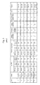
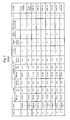
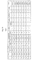
- the content is 10% or more and 30% or less, then particularly desirable characteristics are obtained in terms of landing interference, image deformation, and small dot white spot reproducibility, and furthermore, the lightfastness of the formed image is also good.
- the image forming method comprises the step of fixing the ink on the recording medium after the step of removing the water contained in the solvent of the ink on the recording medium.
- the ink on the recording medium is fixed by thermal pressurizing fixing.
- the step (E) of fixing the ink on the recording medium involves fixing by heating and pressurization.
- the recording medium is a coated paper.
- the present invention is particularly valuable if the recording medium is a coated paper, and enables image disturbance caused by movement of the coloring material to be prevented effectively.
- an image forming apparatus comprising: an aggregating treatment liquid deposition device which deposits an aggregating treatment liquid containing 10% or more and 90% or less of a water-soluble high-boiling-point organic solvent having an SP value of 30 or lower onto a recording medium; an aggregating treatment liquid drying device which dries the aggregating treatment liquid deposited on the recording medium within five seconds after the aggregating treatment liquid is deposited onto the recording medium; an ink droplet ejection device which ejects an ink containing 10% or more and 90% or less of a water-soluble high-boiling-point organic solvent having an SP value of 30 or lower in accordance with an image signal in such a manner that the ink is superimposed on the aggregating treatment liquid deposited on the recording medium; and a water removing device which removes water contained in a solvent of the ink on the recording medium in such a manner that the water contained in the ink becomes 4 g/m 2 or less when
- the image forming apparatus comprising an image fixing device which fixes, onto the recording medium, the ink from which the water has been removed in such a manner that the water contained in the ink becomes 4 g/m 2 or less when converted to a deposition volume.
- the above image forming apparatuses are image forming apparatuses which carry out the image forming methods described above.
- an image forming method and an image forming apparatus which form an image on a recording medium, it is possible to prevent disturbance of the image due to movement of the coloring material even when ink is ejected onto the recording medium.
- treatment liquid An aggregating treatment liquid (hereinafter, also simply called “treatment liquid”) and an ink used in embodiments of the present invention are first described below, and then an image forming method and an image forming apparatus according to embodiments of the present invention are described.
- Treatment liquid (aggregating treatment liquid)
- the treatment liquid it is possible to desirably use a treatment liquid which produces an aggregate by causing the pigment and polymer micro-particles contained in the ink to aggregate by changing the pH of the ink.
- the component of the treatment liquid is selected from amongst: polyacrylic acid, acetic acid, glycol acid, malonic acid, malic acid, malleinic acid, ascorbic acid, succinic acid, glutaric acid, fumaric acid, citric acid, tartaric acid, lactic acid, sulfonic acid, orthophosphoric acid, pyrrolidone carboxylic acid, pyrone carboxylic acid, pyrrole carboxylic acid, furan carboxylic acid, pyridine carboxylic acid, cumaric acid, thiophene carboxylic acid, nicotinic acid, and derivatives of these compounds, and salts of these, and the like.
- a desirable example of the treatment liquid is a treatment liquid to which a multivalent metal salt or polyallylamine has been added. These compounds may be used singly, or a combination of two or more of these compounds may be used.
- the treatment liquid desirably has a pH of 1 to 6, more desirably, a pH of 2 to 5, and particularly desirably, a pH of 3 to 5.
- the added amount, in the treatment liquid, of the compound which causes aggregation of the ink pigment and polymer micro-particles is desirably equal to or greater than 0.01 wt% (% by weight) and equal to or less than 20 wt%, with respect to the total weight of the liquid. If the amount is equal to or less than 0.01 wt%, then when the ink comes into contact with the treatment liquid, the concentration and dispersion do not advance sufficiently, and a sufficient aggregating action may not be produced by a change in the pH. When it is more than 20 wt%, there is a possibility that the ejection performance from an inkjet head declines.
- the treatment liquid contains a water-soluble high-boiling-point organic solvent having an SP value of 30 or lower at a rate of equal to or greater than 10% and equal to or less than 90%.
- a water-soluble high-boiling-point organic solvent having an SP value of 30 or lower are, for instance:
- SP value ((Hildebrand) Solubility Parameter value)
- ⁇ ⁇ ⁇ H - RT / V , where ⁇ H stands for the "molar heat of vaporization”, R stands for the “gas constant”, T stands for the “absolute temperature”, and V stands for the “molar volume”, as known in the art.
- the solvents having a low SP value it is desirable to include the following structure.
- the SP value (solubility parameter) of the water-soluble high-boiling-point organic solvent described here is a value expressed as the square root of the molecular aggregation energy, and this value can be calculated by the method described in R.F. Fedors in Polymer Engineering Science, 14, p.147 (1974 ).
- the unit is (MPa) 1/2 and indicates the value at 25°C.
- water-soluble high-boiling-point organic solvents can be used independently, or in plural fashion, together with other organic solvents.
- the treatment liquid may further include a resin component.
- a resin component Any resin component may be employed, provided that the ejection ability from a head is not degraded when the treatment liquid is ejected by an inkjet system and also provided that the treatment liquid will have high stability in storage.
- water-soluble resins and resin emulsions can be freely used.
- An acrylic resin, a urethane resin, a polyester, a vinyl resin, and a styrene resin can be considered as the resin components.
- a polymer with a comparatively high molecular weight has to be added at a high concentration of 1 wt% to 20 wt%.
- a latex can be effectively added as an adequate material that can be added to a high concentration, while inhibiting the increase in viscosity.
- latex materials include alkyl acrylate copolymers, carboxy-modified SBR (styrene - butadiene latex), SIR (styrene - isoprene) latex, MBR (methyl methacrylate - butadiene latex), and NBR (acrylonitrile - butadiene latex).
- SBR styrene - butadiene latex
- SIR styrene - isoprene
- MBR methyl methacrylate - butadiene latex
- NBR acrylonitrile - butadiene latex
- the aggregation ability may be further improved by introducing polymer microparticles of reverse polarity with respect to that of the ink into the treatment liquid and causing the aggregation of the pigment contained in the ink with the polymer microparticles.
- the aggregation ability may be also improved by introducing a curing agent corresponding to the polymer microparticle component contained in the ink into the treatment liquid, bringing the two liquids into contact, causing aggregation and also crosslinking or polymerization of the resin emulsion in the ink component.
- the treatment liquid can include a surfactant.
- Suitable surfactants of a hydrocarbon system include anionic surfactants such as fatty acid salts, alkylsulfuric acid esters and salts, alkylbenzenesulfonic acid salts, alkylnaphthalenesulfonic acid salts, dialkylsulfosuccinic acid salts, alkylphosphoric acid esters and salts, naphthalenesulfonic acid formalin condensate, and polyoxyethylene alkylsulfuric acid esters and salts, and nonionic surfactants such as polyoxyethyelene alkyl ethers, polyoxyethylene alkylallyl ethers, polyoxyethylene fatty acid esters, sorbitan fatty acid esters, polyoxyethylene sorbitan fatty acid esters, polyoxyethylene alkylamines, glycerin fatty acid esters, and oxyethylene oxypropylene block copolymer.
- anionic surfactants such as fatty acid salts, alkylsul
- SURFYNOLS manufactured by Air Products & Chemicals Co., Ltd.
- Amineoxide-type amphoteric surfactants such as N,N-dimethyl-N-alkylamineoxide is also a preferred surfactant.
- a surfactant described in Japanese Patent Application Publication No. 59-157636 , pages 37 to 38 and Research Disclosure No. 308119 (1989 ) can be also used.
- Fluorine-containing (fluorinated alkyl system) and silicone-type surfactants such as described in Japanese Patent Application Publication Nos. 2003-322926 , 2004-325707 , and 2004-309806 can be also used.
- These surface tension adjusting agents can be also used as an antifoaming agent.
- Chelating agents represented by fluorine-containing or silicone-type compounds and EDTA can be also used.
- the surface tension of the treatment liquid is desirably 10 to 50 mN/m, and furthermore, from the viewpoint of simultaneously achieving wetting properties on an intermediate transfer medium, a fine liquid droplet size, and good ejection properties, a surface tension of 15 to 45 mN/m is desirable.
- the viscosity of the treatment liquid is 1.0 to 20.0 cP.
- a pH buffering agent an antioxidant, an anti-rusting agent, a mildewcide, a viscosity adjuster, a conducting agent, an ultraviolet absorber, and the like.
- the ink it is possible to use a water-soluble pigment-based ink which contains, as solvent-insoluble materials, a pigment which is a coloring material (colorant) and polymer micro-particles and the like.
- the density of the solvent-insoluble material is equal to or greater than 1 wt% and equal to or less than 20 wt%, taking account of the fact that the suitable viscosity for ejection is 20 mPa ⁇ s or lower. More desirably, the density of the pigment is 4 wt% or above, in order to obtain good optical density in the image.
- the surface tension of the ink is equal to or greater than 20 mN/m and equal to or less than 40 mN/m, taking account of ejection stability.
- the coloring material used in the ink may be pigment particles or a combination of dye and pigment. From the viewpoint of the aggregating properties upon contact with the treatment liquid, a pigment which is in a dispersed state in the ink is desirable, since this aggregates more effectively. Of pigments, it is particularly desirable to use a pigment which is dispersed by a dispersant, a self-dispersing pigment, a pigment in which the surfaces of the pigment particles are covered with a resin (microcapsule pigment), or a polymer grafted pigment. Furthermore, from the viewpoint of the aggregating properties of the pigment, a more desirable mode is one where the pigment is modified with a carboxyl group having a low degree of disassociation.
- this resin desirably has a numerical average molecular weight in the range of approximately 1,000 to 100,000, and particularly desirably, in the range of approximately 3,000 to 50,000.
- the resin is formed as a solution by dissolving in an organic solvent.
- the resin it is possible for the resin to be self-dispersing or soluble, or for these functions to be imparted to the polymer by means of some kind.
- a resin in which one or two or more of the same anionic group or different anionic groups has been introduced.
- an orange or yellow pigment there are no particular restrictions on the pigment used, but possible specific examples of an orange or yellow pigment are, for instance: C.I. Pigment Orange 31, C.I. Pigment Orange 43, C.I. Pigment Yellow 12, C.I. Pigment Yellow 13, C.I. Pigment Yellow 14, C.I. Pigment Yellow 15, C.I. Pigment Yellow 17, C.I. Pigment Yellow 74, C.I. Pigment Yellow 93, C.I. Pigment Yellow 94, C.I. Pigment Yellow 128, C.I. Pigment Yellow 138, C.I. Pigment Yellow 151, C.I. Pigment Yellow 155, C.I. Pigment Yellow 180, C.I. Pigment Yellow 185, and the like.
- red or magenta pigment Possible examples are, for instance: C.I. Pigment Red 2, C.I. Pigment Red 3, C.I. Pigment Red 5, C.I. Pigment Red 6, C.I. Pigment Red 7, C.I. Pigment Red 15, C.I. Pigment Red 16, C.I. Pigment Red 48:1, C.I. Pigment Red 53:1, C.I. Pigment Red 57:1, C.I. Pigment Red 122, C.I. Pigment Red 123, C.I. Pigment Red 139, C.I. Pigment Red 144, C.I. Pigment Red 149, C.I. Pigment Red 166, C.I. Pigment Red 177, C.I. Pigment Red 178, C.I. Pigment Red 222, and the like.
- green or cyan pigment Possible examples are, for instance: C.I. Pigment Blue 15, C.I. Pigment Blue 15:2, C.I. Pigment Blue 15:3, C.I. Pigment Blue 16, C.I. Pigment Blue 60, C.I. Pigment Green 7, and the like.
- black pigment examples include, for instance: C.I. Pigment Black 1, C.I. Pigment Black 6, C.I. Pigment Black 7, and the like.
- polymer micro-particles which do not contain a colorant are added to a coloring ink liquid.
- the polymer micro-particles enhance the aggregating action and viscosity increasing action of the ink upon reaction with the treatment liquid, and thereby make it possible to improve the image quality.
- the method of dispersing in a polymer ink is not limited to an emulsion, and it may be present in the state of a solution or in the state of a colloidal dispersion.
- the polymer micro-particles may be dispersed by using an emulsifier, or without using an emulsifier.
- an emulsifier generally, a surfactant of low molecular weight is used, but it is also possible to use a surfactant of high molecular weight as the emulsifier.
- capsule type polymer micro-particles in which the outer shell is made of acrylic acid, methacrylic acid, or the like namely, core - shell type polymer micro-particles which have a different composition between the central portion and the outer edge portion).
- polymer micro-particles which do not use a low-molecular weight surfactant include polymer micro-particles using a high-polymer surfactant and polymer micro-particles which do not include an emulsifier, and these are known as a soap-free latex.
- this includes polymer micro-particles which use, as an emulsifier, a polymer having a group which is soluble in water, such as a sulfonate group, a carboxylic acid group, or the like, as described above (a polymer with a grafted soluble group, or a block polymer obtained from a monomer having a soluble group and a monomer having an insoluble part).
- a soap-free latex since compared to polymer micro-particles which are polymerized using a conventional emulsifier, a soap-free latex avoids concerns such as the emulsifier obstructing the reaction aggregation and film formation of the polymer micro-particles, and the separated emulsifier moving to the surface after the formation of a film of the polymer micro-particles and reducing the adhesiveness between the aggregate body formed by the combined pigment and polymer micro-particles and the recording medium.
- a resin component which is added to the ink in the form of polymer micro-particles include: an acrylic resin, a vinyl acetate resin, a styrene-butadiene resin, a vinyl chloride resin, an acryl-styrene resin, a butadiene resin, a styrene resin, and the like.
- a material having a carboxylic acid group with a low degree of disassociation is more desirable, from the viewpoint of imparting fast aggregating properties to the polymer micro-particles. Since the carboxylic acid group is liable to be affected by change in the pH, the state of dispersion is liable to change, and hence the aggregating properties are high.
- the change in the state of dispersion of the polymer micro-particles caused by change in the pH can be adjusted by means of the content ratio of the constituent components of the polymer micro-particles which contain a carboxylic acid group, such as ester acrylate, or the like, and it can also be adjusted by means of an anionic surfactant which is used as a dispersant.
- the resin component of the polymer micro-particles is a polymer which combines a hydrophilic part and a hydrophobic part.
- the hydrophobic part is oriented toward to the inner side of the polymer micro-particle, and the hydrophilic part is oriented efficiently toward the outer side, thereby having the effect of further increasing the change in the dispersion state caused by change in the pH of the liquid. Therefore, aggregation can be performed more efficiently.
- a carboxylic acid polymer is used as an acid polymer.
- the pKa of carboxylic acid is approximately 3 to 4, then if the pH is 5, the acid polymer assumes an almost separated state and therefore has stable dispersion characteristics due to electric repulsion, and aggregation does not occur. If the pH is lower than this, then the polymer assumes a non-separated state, the electric repulsion is lost and aggregation arises.
- Examples of commercial polymer micro-particles include: Joncryl 537, 7640 (a styrene - acrylic resin emulsion, made by Johnson Polymer Corp.), Microgel E-1002, E-5002 (a styrene - acrylic resin emulsion, made by Nippon Paint Co., Ltd.), Boncoat 4001 (an acrylic resin emulsion, made by DIC Corporation), Boncoat 5454 (a styrene - acrylic resin emulsion, made by DIC Corporation), SAE-1014 (a styrene - acrylic resin emulsion, made by Zeon Corporation), Jurymer ET-410, FC-30, (an acrylic resin emulsion, made by Nihonjunyaku Co., Ltd.), Aron HD-5, A-104 (an acrylic resin emulsion, made by Toagosei Co., Ltd.), Saibinol SK-200 (an acrylic resin emulsion, made by Saiden Chemical Industry Co., Ltd.), "Za
- the weight ratio of the added amount of polymer micro-particles with respect to the pigment is desirably from 2:1 to 1:10, and more desirably, from 1:1 to 1:3. If the weight ratio of the added amount of polymer micro-particles with respect to the pigment is smaller than 2:1, then the aggregating force of the aggregate body is not increased effectively by the fusion of the resin. Moreover, even if the added amount is greater than 1:10, the viscosity of the ink becomes too high and the ejection reliability and other factors deteriorate.
- the molecular weight of the polymer micro-particles added to the ink should be 5,000 or greater. If the molecular weight is less than 5,000, then insufficient effects are obtained in increasing the internal aggregating force of the ink aggregate body when aggregation occurs, or improving the fixing properties of the image to the recording medium, and furthermore, the effects in improving image quality are inadequate.
- the volume-average particle size (diameter) of the polymer micro-particles is in the range of 10 nm to 1 ⁇ m, more desirably, the range of 10 to 500 nm, even more desirably, the range of 20 to 200 nm, and particularly desirably, the range of 50 to 200 nm. If the particle size is less than 10 nm, then significant effects in improving the image quality or enhancing transfer characteristics cannot be expected, even if aggregation occurs. If the particle size is equal to or greater than 1 ⁇ m, then there is a possibility that the ejection characteristics from the ink head or the storage stability deteriorate. Furthermore, there are no particular restrictions on the volume-average particle size distribution of the polymer particles; therefore, they may have a broad volume-average particle size distribution, or they may have a mono-disperse volume-average particle size distribution.
- two or more types of polymer micro-particles may be used in combination in the ink.
- an organic salt or an inorganic alkaline base as a neutralizing pH adjuster which is added to the ink.
- a pH adjuster is added so as to adjust the ink to a pH of 6 to 10, in order to improve the storage stability of the inkjet ink.
- the water-soluble high-boiling-point organic solvent having an SP value of 30 or lower is contained at a rate of 10 wt% to 90 wt% with the object of preventing blockages of the nozzles of the inkjet head due to drying.
- a water-soluble high-boiling-point organic solvent of this kind includes a moistening agent or a penetrating agent.
- water-soluble high-boiling-point organic solvents having an SP value of 30 or lower include, for instance:
- the solvents having a low SP value it is desirable to include the following structure.
- the ink may also contain a surfactant.
- a surfactant in a hydrocarbon system, an anionic surfactant, such as a salt of a fatty acid, an alkyl sulfate ester, an alkyl benzene sulfonate, an alkyl naphthalene sulfonate, a dialkyl sulfosuccinate, an alkyl phosphate ester, a naphthalene sulfonate / formalin condensate, a polyoxyethylene alkyl sulfuric ester, and the like; and a non-ionic surfactant, such as a polyoxyethylene alkyl ether, a polyoxyethylene alkyl aryl ether, a polyoxyethylene fatty acid ester, a sorbitan fatty acid ester, a polyoxyethylene sorbitan fatty acid ester, a polyoxyethylene alkyl amine, a glycerine fatty acid este
- SURFYNOLS Air Products & Chemicals, Inc.
- SURFYNOLS Air Products & Chemicals, Inc.
- an amine oxide type of amphoteric surfactant such as N,N-dimethyl-N-alkyl amine oxide, is also desirable.
- the surface tension of the ink is 15 to 45 mN/m, from the viewpoint of simultaneously achieving good wetting properties on an intermediate transfer medium when recording by an intermediate transfer method, as well as finer size of the liquid droplets and good ejection characteristics.
- the ink viscosity is 1.0 to 20.0 cP.
- a pH buffering agent an antioxidant, an anti-rusting agent, a mildewcide, a viscosity adjuster, a conducting agent, an ultraviolet absorber, or the like.
- Fig. 1 is a general schematic drawing illustrating an image forming apparatus according to an embodiment of the present invention.
- the image forming apparatus 100 illustrated in Fig. 8 is a single side machine, which is capable of printing only onto one surface of a recording medium 114.
- the image forming apparatus 100 includes: a paper supply unit 102, which supplies the recording medium 114; a treatment agent deposition unit 106, which deposits treatment agent onto the recording medium 114; a print unit (image forming unit) 108, which forms an image by depositing the colored inks onto the recording medium 114; a fixing unit 110 fixing the ink on the recording medium 114 onto the recording medium 114; and a paper output unit 112, which conveys and outputs the recording medium 114 on which the image has been formed.
- a paper supply platform 120 on which the recording media 114 are stacked is provided in the paper supply unit 102.
- a feeder board 122 is connected to the front (the left-hand side in Fig. 1 ) of the paper supply platform 120, and the recording media 114 stacked on the paper supply platform 120 are supplied one sheet at a time, successively from the uppermost sheet, to the feeder board 122.
- the recording medium 114 that has been conveyed to the feeder board 122 is supplied through a transfer drum 124b to the surface (circumferential surface) of a pressure drum 126b of the treatment agent deposition unit 106.
- the treatment agent deposition unit 106 is provided following the paper supply unit 102.
- the transfer drum 124b is provided between the paper supply unit 102 and the pressure drum 126b of the treatment agent deposition unit 106 so as to make contact with them.
- the recording medium 114 is conveyed to the pressure drum 126b of the treatment agent deposition unit 106 via the transfer drum 124b
- the paper preheating unit 134 and the treatment liquid drying unit 138 have heaters that can be temperature-controlled within prescribed ranges, respectively.
- the recording medium 114 held on the pressure drum 126b passes through the positions opposing the paper preheating unit 134 and the permeation suppression agent drying unit 138, it is heated by the heaters of these units.
- the treatment liquid head 136 ejects droplets of the treatment liquid onto the recording medium 114 held on the pressure drum 126b, and can have the same structure as each of the ink heads 140C, 140M, 140Y, and 140K of the print unit 108 described later.
- An inkjet head is used as the device depositing the treatment liquid on the surface of the recording medium 114 in the present embodiment; however, a device depositing the treatment liquid is not limited to the present embodiment.
- Such a device applying the treatment liquid may employ various methods, such as a spray method and a roller applying method.
- the treatment liquid used in the present embodiment is an acidic liquid which aggregates the coloring materials contained in the inks ejected toward the recording medium 114 from the respective ink heads 140C, 140M, 140Y and 140K arranged in the print unit 108, which is located in the latter stage.
- the heating performed by the heater of the treatment liquid drying unit 138 is carried out within 5 seconds of depositing the treatment liquid on the surface of the recording medium 114 by the treatment liquid head 136. Consequently, it is desirable that the treatment liquid drying unit 138 should be located in the vicinity of the treatment liquid head 136.
- the heating temperature of the heater of the treatment liquid drying unit 138 is set to a temperature whereby the treatment liquid is dried and a solid or semi-solid layer of aggregating treatment agent (a thin layer of dried treatment liquid) is formed on the recording medium 114.
- a layer of aggregating treatment agent in a solid state or a semi-solid state includes a layer having a water content of 0% to 70%.
- a “solid or semi-solid aggregating treatment agent (aggregating treatment agent layer)" indicates a water content ratio of 0 to 70% in the aggregating treatment agent (aggregating treatment agent layer).
- water content ratio means the ratio between the weight X 1 (g/m 2 ) per unit surface area of the aggregating treatment agent and the weight X 2 (g/m 2 ) per unit surface area of the water contained in the aggregating treatment agent (i.e. X 2 / X 1 ).
- the drying of the aggregating treatment liquid must start within 5 seconds after the application of the treatment liquid. Dot white spot reproducibility is obtained if drying is carried out within 5 seconds, and curling can also be suppressed.
- a desirable mode is one in which the recording medium 114 is preheated by the heater of the paper preheating unit 134, before depositing the treatment liquid on the recording medium 114, as in the present embodiment. In this case, it is possible to restrict the heating energy required to dry the treatment liquid to a low level, and therefore energy savings can be made.
- the print unit 108 is arranged after the treatment liquid deposition unit 106.
- a transfer drum 124c is arranged between the pressure drum 126b of the treatment liquid deposition unit 106 and a pressure drum 126c of the print unit 108, so as to make contact with same.
- the recording medium 114 is transferred through the transfer drum 124c to the pressure drum 126c of the print unit 108.
- the print unit 108 is provided with the ink heads 140C, 140M, 140Y and 140K, which correspond respectively to the four colors of ink, C, M, Y and K, and solvent drying units 142a and 142b at positions opposing the surface of the pressure drum 126c, in this order from the upstream side in terms of the direction of rotation of the pressure drum 126c (the counter-clockwise direction in Fig. 1 ).
- the ink heads 140C, 140M, 140Y and 140K employ the inkjet type recording heads (inkjet heads), similarly to the treatment liquid head 136.
- the ink heads 140C, 140M, 140Y and 140K respectively eject droplets of corresponding colored inks onto the recording medium 114 held on the pressure drum 126c.
- Each of the ink heads 140C, 140M, 140Y and 140K is a full-line head having a length corresponding to the maximum width of the image forming region of the recording medium 114 held on the pressure drum 126c, and having a plurality of nozzles 161 (not illustrated in Fig. 1 ) for ejecting the ink, which are arranged on the ink ejection surface of the head through the full width of the image forming region.
- the ink heads 140C, 140M, 140Y and 140K are arranged so as to extend in a direction that is perpendicular to the direction of rotation of the pressure drum 126c (the conveyance direction of the recording medium 114).
- the full line heads having the nozzle rows covering the full width of the image forming region of the recording medium 114 are provided respectively for the colors of ink, it is possible to record a primary image on the image forming region of the recording medium 114 by performing just one operation of moving the recording medium 114 and the ink heads 140C, 140M, 140Y and 140K relatively with respect to each other (in other words, by one sub-scanning action). Therefore, it is possible to achieve a higher printing speed compared to a case that uses a serial (shuttle) type of head moving back and forth reciprocally in the main scanning direction, which is the direction perpendicular to the sub-scanning direction or the conveyance direction of the recording medium 114, and hence it is possible to improve the print productivity.
- a serial (shuttle) type of head moving back and forth reciprocally in the main scanning direction, which is the direction perpendicular to the sub-scanning direction or the conveyance direction of the recording medium 114, and hence it is possible to improve the print productivity.
- the combinations of the ink colors and the number of colors are not limited to those.
- Light and/or dark inks, and special color inks can be added as required.
- ink heads for ejecting light-colored inks, such as light cyan and light magenta are added.
- Each of the solvent drying units 142a and 142b has a composition including a heater of which temperature can be controlled within a prescribed range, similarly to the paper preheating unit 134, the permeation suppression agent drying unit, and the treatment liquid drying unit 138 described above.
- a heater of which temperature can be controlled within a prescribed range, similarly to the paper preheating unit 134, the permeation suppression agent drying unit, and the treatment liquid drying unit 138 described above.
- the solvent component (liquid component) left on the recording medium 114 in this way is a cause of curling of the recording medium 114 and also leads to deterioration of the image. Therefore, in the present embodiment, after depositing the droplets of the corresponding colored inks from the ink heads 140C, 140M, 140Y and 140K onto the recording medium 114, heating is carried out by the heaters of the solvent drying units 142a and 142b, and the solvent component is evaporated off and the recording medium 114 is dried.
- water contained in the solvent of ink is reduced in such a manner that the water becomes equal to or less than 4 g/m 2 when converted to a deposition volume.
- the method of reducing the solvent may be any methods that reduce the solvent on the substrate, but methods which use drying as in the present embodiment or a solvent absorbing member are desirable.
- a method using drying a method using heat, a method using wind, or a method using both heat and wind is desirably used for example.
- a non-contact heating method using a device emitting radiant heat such as IR heater (Infrared Heater), or a method using both of them can be desirably used for example.
- a method using a solvent absorbing member a method using a porous member is desirably used.
- the porosity diameter of such a porous member is desirably from 1 ⁇ m to 100 ⁇ m, and more desirably from 5 ⁇ m to 80 ⁇ m.
- a polymer porous member, a ceramics porous member, or a metallic porous member can be used. In cases of using a polymer porous member as the material of such a porous member, a soft material can be selected and this is desirable in increasing the adhesiveness against the surface of the substrate. From the view point of carrying out continuous processing, the roller shape is desirable.
- the fixing unit 110 is provided following the print unit 108.
- a transfer drum 124d is arranged between the pressure drum 126c of the print unit 108 and the pressure drum 126d of the fixing unit 110 so as to make contact with same. Hence, the recording medium 114 held on the pressure drum 126c of the print unit 108 is transferred through the transfer drum 124d to the pressure drum 126d of the fixing unit 110.
- the fixing unit 110 includes a heating roller 144 the temperature of which is adjustable in the range of 50°C through 200°C, and fixes the image onto the recording medium 114 while heating and pressurizing the recording medium sandwiched between the pressure drum 126d and the heating roller 144.
- the heating temperature of the fixing unit 110 is desirably set according to the temperature of glass transition point of the polymer fine particles contained in the ink, or the like. In the present embodiment, the heating temperature of the fixing unit 110 is set to 130°C.
- the nip pressure of the fixing unit 110 is desirably set to 0.5 MPa thorough 10 MPa.
- the paper output unit 112 is provided following the fixing unit 110.
- the paper output unit 112 is provided with a paper outputting drum 150 which receives the recording medium 114, a paper outputting base 152 which accommodates the recording media 114, and a paper outputting chain 154 which is provided between a sprocket of the paper outputting drum 150 and a sprocket arranged above the paper outputting base 152 and has a plurality of grippers for outputting paper.
- the recording medium 114 transferred to the paper outputting drum 150 from the pressure drum 126d is conveyed to the paper outputting base 152 by the paper outputting chain 154.
- the recording medium is coated paper.
- a recording medium having low permeability such as coated paper
- the aggregated ink coloring material in the aggregating treatment liquid floats and does not remain in the desired position, and consequently the output image is greatly disturbed in comparison with the desired image.
- the present embodiment is particularly valuable if the recording medium is a coated paper, and enables image disturbance caused by movement of the coloring material to be prevented effectively.
- support media which can be used appropriately for coated paper include: an art paper, a coated paper, and other coated papers such as a cast coated paper, in which a coat layer is provided on a base paper, a size press layer or an anchor coating layer formed using starch, polyvinyl alcohol, or the like is provided on a base paper, or a coat layer is provided on such a size press layer or an anchor coating layer.
- Such a base paper can be manufactured from main components of wood pulp and pigment mixed with a binder and one or more additive of a sizing agent, fixing agent, yield enhancer, cationization agent, paper strength enhancer, and other additive agents, by using various machines, such as a Fourdrinier paper machine, a cylindrical paper machine, a twin-wire paper machine, and the like.
- the pulp is either a chemical pulp such as LBKP or NBKP, a mechanical pulp such as GP, PGW, RMP, TMP, CTMP, CMP, CGP, or the like, or recovered paper pulp such as DIP.
- the coated paper used in embodiments of the present invention has a coating layer formed on the support medium described above.
- the coating layer comprises a coating composition including a pigment and a binder as main components thereof, and at least one coating layer is formed on the support medium.
- the white pigment it is desirable to use a white pigment.
- the white pigment include: an inorganic pigment, such as precipitated calcium carbonate, heavy calcium carbonate, magnesium carbonate, kaolin, talc, calcium sulfate, barium sulfate, titanium dioxide, zinc acid, zinc sulfide, zinc carbonate, satin white, aluminum silicate, diatomaceous earth, calcium silicate, magnesium silicate, synthetic non-crystalline silica, colloidal silica, alumina, colloidal alumina, pseudo-boehmite, aluminum hydroxide, lithopone, zeolite, hydrated halloysite, magnesium hydroxide, and the like; and an organic pigment, such as a styrene-based plastic pigment, an acrylic plastic pigment, polyethylene, microcapsules, urea resin, melamine resin, and the like.
- an inorganic pigment such as precipitated calcium carbonate, heavy calcium carbonate, magnesium carbonate, kaolin, talc, calcium sulfate, bar
- the binder may be, for instance: a starch derivative, such as oxidized starch, etherified starch, or phosphoric acid esterized starch; a cellulose derivative, such as carboxymethyl cellulose, hydroxyethyl cellulose, or the like; casein, gelatine, soybean protein, polyvinyl alcohol, or derivatives of same; polyvinyl alcohols having various degrees of saponification or silanol-denatured versions of same, or carboxylates, cationized products, of other derivatives of same; polyvinyl pyrrolidone, maleic anhydride resin, a styrene - butadiene copolymer, a methyl methacrylate - butadiene copolymer, or other conjugated diene copolymer latex; an acrylic polymer latex, such as a polymer or copolymer of acrylate ester and methacrylate ester; a vinyl polymer latex, such as such as an ethylene acetate
- the combination ratio of the pigment and binder in the coating layer is 3 to 70 parts by weight, and desirably 5 to 50 parts by weight, of binder with respect to 100 parts by weight of pigment. If the combination ratio of the binder with respect to 100 parts by weight of pigment is less than 3 parts by weight, then the coating of the ink receiving layer by the coating composition will have insufficient strength. On the other hand, if the combination ratio is greater than 70 parts by weight, then the supply of high-boiling-point solvent is slowed dramatically.
- a dye fixing agent a pigment dispersant, a viscosity raising agent, a fluidity enhancer, an antifoaming agent, a foam suppressant, a separating agent, a foaming agent, a permeating agent, a coloring dye, a coloring pigment, a fluorescent brightener, an ultraviolet light absorber, an antioxidant, an anticorrosive, an antibacterial agent, a waterproofing agent, a wet paper strength enhancer, a dry paper strength enhancer, or the like.
- the application amount of the ink receiving layer varies depending on the required gloss, the ink absorbing properties and the type of support medium, or the like, and although no general figure can be stated, it is normally 1 g/m 2 or greater. Furthermore, the ink receiving layer can also be applied by dividing a certain uniform application amount into two application steps. If application is divided into two steps in this way, then the gloss is improved in comparison with a case where the same application amount is applied in one step.
- the application of the coating layer can be carried out using one of various type of apparatus, such as a blade coater, roll coater, air knife coater, bar coater, rod blade coater, curtain coater, short dowel coater, size press, or the like, in on-machine or off-machine mode. Furthermore, after application of the coating layer, it is also possible to carry out a smoothing and finishing process on the ink receiving layer by using a calender apparatus, such as a machine calender, a TG calender, a soft calender, or the like.
- a calender apparatus such as a machine calender, a TG calender, a soft calender, or the like.
- the number of coating layers can be determined appropriately in accordance with requirements.
- the coating paper may be an art paper, high-quality coated paper, medium-quality coated paper, high-quality lightweight coated paper, medium-quality lightweight coated paper, or light-coated printing paper; the application amount of the coating layer is around 40 g/m 2 on both surfaces in the case of art paper, around 20 g/m 2 on both surfaces in the case of high-quality coated paper or medium-quality coated paper, around 15 g/m 2 on both surfaces in the case of high-quality lightweight coated paper or medium-quality lightweight coated paper, and around 12 g/m 2 or less on both surfaces in the case of a light-coated printing paper.
- An example of an art paper is Tokubishi Art, or the like; an example of a high-quality coated paper is "U-Lite"; examples of art papers are Tokubishi Art (made by Mitsubishi Paper Mills Co., Ltd.), Golden Cask Satin (made by Oji Paper Co., Ltd.), or the like; examples of coated papers are OK Top Coat (made by Oji Paper Co., Ltd.), Aurora Coat (made by Nippon Paper Group Inc.), Recycle Coat T-6 (made by Nippon Paper Group Inc.); examples of lightweight coated papers are U-Lite (made by Nippon Paper Group Inc.), New V Matt (made by Mitsubishi Paper Mills Co., Ltd.), New Age (made by Oji Paper Co., Ltd.), Recycle Mat T-6 (made by Nippon Paper Group Inc.), and "Pism” (made by Nippon Paper Group Inc.).
- Examples of light-coated printing papers are Aurora L (made by Nippon Paper Group Inc.) and Kinmari Hi-L (made by Hokuetsu Paper Mills, Ltd.), or the like.
- examples of cast coated papers are: SA Gold Cask plus (made by Oji Paper Group Inc.), Hi-McKinley Art (Gojo Paper Mfg. Co., Ltd.), or the like.
- an image is formed by depositing a treatment liquid on a base material, drying the treatment liquid, ejecting droplets of ink and then drying the ink.
- the treatment liquid head supplies an aggregating treatment liquid at a thickness of 5 ⁇ m to the whole surface of the base material inserted into the apparatus.
- the aggregating treatment liquid is applied by means of an application apparatus such as a roller, rather than an inkjet head.
- an application apparatus such as a roller
- the treatment liquid can be applied in a thinner layer than when using an inkjet head, and in this case also, the drying time can be shortened and the required heating energy can be reduced.
- the base material is dried at a downstream stage by a heating unit (more specifically, it is dried for one second by a transfer drum at 60°C and a hot air flow at 70°C), thereby forming a solid or semi-solid layer of aggregating treatment agent on the base material.
- a heating unit more specifically, it is dried for one second by a transfer drum at 60°C and a hot air flow at 70°C
- droplets of the CMYK inks are ejected from the heads in accordance with an image signal. Recording is carried out at an ink ejection volume of 2 pl and a recording density of 1200 dpi in both the main scanning direction and the sub-scanning direction.
- the base material is dried in a heating section (more specifically, dried for two seconds by a transfer drum at 25°C and a hot air flow at 70°C, then dried for one second by a pressure drum at 50°C and a hot air flow at 70°C, and then dried for two seconds by a pressure drum at 60°C and a hot air flow at 70°C).
- the base material on which the image has been formed is heated and fixed by a pressure drum at 60°C, and a roller at a temperature of 110°C and a nip pressure of 1 MPa.
- a polymer resin in the form of micro-particles
- the heating temperature is set in accordance with the melting temperature of the polymer resin.
- U-Lite a matt coated paper
- various other types of media can be used according to need.
- Image formation was carried out using the image forming apparatus illustrated in Fig. 1 , under the system conditions illustrated in Fig. 1 (hereinafter, called system conditions A), under the system conditions using the image forming apparatus in Fig. 1 from which the aggregating treatment liquid drying unit 138 was removed (hereinafter, called system conditions B), and under the system conditions using the image forming apparatus in Fig. 1 from which the aggregating treatment liquid application unit and the aggregating treatment liquid drying unit were removed (hereinafter, called system conditions C).
- system conditions A system conditions illustrated in Fig. 1
- system conditions B under the system conditions using the image forming apparatus in Fig. 1 from which the aggregating treatment liquid drying unit 138 was removed
- system conditions C under the system conditions using the image forming apparatus in Fig. 1 from which the aggregating treatment liquid application unit and the aggregating treatment liquid drying unit were removed
- An aggregating treatment agent was prepared by mixing materials according to the following composition.
- 88 g of methylethyl ketone was introduced into a 1000 ml three-mouthed flask fitted with an agitator and a cooling tube, and was heated to 72°C in a nitrogen atmosphere, whereupon a solution formed by dissolving 0.85 g of dimethyl 2,2'-azobis isobutylate, 60 g of benzyl methacrylate, 10 g of methacrylic acid and 30 g of methyl methacrylate in 50 g of methylethyl ketone 50 g was added to the flask by titration over 3 hours.
- Pigment Blue 15:3 (phthalocyanine blue A220 made by Dainichi Seika Color & Chemicals Mfg. Co., Ltd.), 5 parts of the polymer dispersant P-1 obtained as described above, 42 parts of methylethyl ketone, 5.5 parts of an aqueous 1 mol/L NaOH solution, and 87.2 parts of deionized water were mixed together, and dispersed for 2 to 6 hours using 0.1 mm diameter zirconia beads in a beads mill.
- the methylethyl ketone was removed from the obtained dispersion at 55°C under reduced pressure, and moreover a portion of the water was removed, thus obtaining a cyan dispersion liquid having a pigment density of 10.2 percent by mass.
- the cyan dispersion liquid forming a coloring material was prepared as described above. Using the coloring material (cyan dispersion liquid) obtained as described above, an ink 1 (inkjet recording liquid) was manufactured by combining the respective components so as to achieve the ink composition described below.
- a base material was dried at a downstream stage by a heating unit (more specifically, it was dried for one second by a transfer roller at 60°C and a hot air flow at 70°C), thereby forming a solid or semi-solid layer of aggregating treatment agent on the base material.
- droplets of the CMYK inks were ejected from the heads in accordance with an image signal. Recording was carried out at an ink ejection volume of 2 pl and a recording density of 1200 dpi in both the main scanning direction and the sub-scanning direction.
- the base material was dried in a heating section (more specifically, dried for two seconds by a transfer drum at 25°C and a hot air flow at 70°C, then dried for one second by a pressure drum at 50°C and a hot air flow at 70°C, and then dried for two seconds by a pressure drum at 60°C and a hot air flow at 70°C).
- GP-250 means a trioxypropylene glyceryl ether, Sannix GP250, made by Sanyo Chemical Industries, Ltd.
- a sample printed at a print rate of 250% was cut to 5 ⁇ 50 mm in such a manner that the longer edges traced an arc, and the curvature C of the sample was measured as described below. Curl was evaluated on the basis of the following evaluation criteria.
- the curvature C of a sample onto which inkjet recording liquid had been applied was measured in an environment of a temperature of 25°C and a relative humidity of 50%.
- the curl value C is expressed as an arc of a circle of radius R, as indicated in Expression 1 below.
- C 1 / R m
- condition L a mode using a solvent absorbing roller rather than drying was also investigated.
- Table 5 and Table 6 in Figs. 6 and 7 indicate the conditions and the corresponding results.
- a sample printed at a print rate of 100% was illuminated continuously for 20 days with a xenon lamp at 99,000 lux.
- the gloss was measured using an IG-331 handheld gloss checker (manufactured by HORIBA, Ltd).
Landscapes
- Chemical & Material Sciences (AREA)
- Life Sciences & Earth Sciences (AREA)
- Engineering & Computer Science (AREA)
- Materials Engineering (AREA)
- Wood Science & Technology (AREA)
- Organic Chemistry (AREA)
- Chemical Kinetics & Catalysis (AREA)
- Ink Jet Recording Methods And Recording Media Thereof (AREA)
- Ink Jet (AREA)
- Inks, Pencil-Leads, Or Crayons (AREA)
Applications Claiming Priority (1)
| Application Number | Priority Date | Filing Date | Title |
|---|---|---|---|
| JP2008077724A JP2009226848A (ja) | 2008-03-25 | 2008-03-25 | 画像形成方法及び画像形成装置 |
Publications (1)
| Publication Number | Publication Date |
|---|---|
| EP2105473A1 true EP2105473A1 (fr) | 2009-09-30 |
Family
ID=40872744
Family Applications (1)
| Application Number | Title | Priority Date | Filing Date |
|---|---|---|---|
| EP20090004247 Withdrawn EP2105473A1 (fr) | 2008-03-25 | 2009-03-25 | Procédé et appareil de formation d'image |
Country Status (4)
| Country | Link |
|---|---|
| US (1) | US8182079B2 (fr) |
| EP (1) | EP2105473A1 (fr) |
| JP (1) | JP2009226848A (fr) |
| CN (1) | CN101544102A (fr) |
Cited By (3)
| Publication number | Priority date | Publication date | Assignee | Title |
|---|---|---|---|---|
| EP2221351A1 (fr) * | 2009-02-20 | 2010-08-25 | FUJIFILM Corporation | Jeu d'encre pour une impression à jet d'encre et procédé d'impression d'images |
| FR2951402A1 (fr) * | 2009-10-19 | 2011-04-22 | Polypore | Procede d'impression par jet d'encre pour encre fonctionnelle sur tout support |
| WO2017140713A1 (fr) * | 2016-02-19 | 2017-08-24 | OCE Holding B.V. | Composition de prétraitement |
Families Citing this family (6)
| Publication number | Priority date | Publication date | Assignee | Title |
|---|---|---|---|---|
| JP5089629B2 (ja) * | 2009-02-19 | 2012-12-05 | 株式会社リコー | 画像形成装置及び画像形成方法 |
| US9114636B2 (en) * | 2011-06-01 | 2015-08-25 | Koenig & Bauer Aktiengesellschaft | Printing machine and method for adjusting a web tension |
| US9272540B2 (en) * | 2011-08-17 | 2016-03-01 | Hewlett-Packard Development Company, L.P. | Printing system and method |
| JP2013223929A (ja) * | 2012-04-19 | 2013-10-31 | Seiko Epson Corp | インクジェット記録装置およびインクジェット記録方法 |
| JP2017186455A (ja) * | 2016-04-06 | 2017-10-12 | セイコーエプソン株式会社 | 処理液組成物及び捺染方法 |
| EP3490723A4 (fr) * | 2016-07-26 | 2020-03-18 | Berry film Products company, Inc. | Films thermoplastiques profilés |
Citations (13)
| Publication number | Priority date | Publication date | Assignee | Title |
|---|---|---|---|---|
| JPS59157636A (ja) | 1983-02-25 | 1984-09-07 | Fuji Photo Film Co Ltd | カラ−画像形成方法 |
| EP0778321A2 (fr) * | 1995-12-08 | 1997-06-11 | Seiko Epson Corporation | Assortiment d'encre pour l'enregistrement à jet d'encre et méthode d'enrégistrement l'utilisant |
| JPH11188858A (ja) | 1997-12-26 | 1999-07-13 | Ricoh Co Ltd | 記録方法及び装置 |
| EP1088865A1 (fr) * | 1999-09-29 | 2001-04-04 | Seiko Epson Corporation | Composition d'encre et procédé d'enregistrement par jet d'encre utilisant cette composition |
| EP1132438A2 (fr) * | 2000-03-10 | 2001-09-12 | Canon Kabushiki Kaisha | Procédé d'impression par jet d'encre |
| JP2003322926A (ja) | 2002-05-02 | 2003-11-14 | Fuji Photo Film Co Ltd | ハロゲン化銀写真感光材料 |
| JP2004010633A (ja) | 2002-06-03 | 2004-01-15 | Fuji Xerox Co Ltd | インクジェット記録方法、及びインクジェット記録用インクセット |
| JP2004309806A (ja) | 2003-04-08 | 2004-11-04 | Fuji Photo Film Co Ltd | ハロゲン化銀写真感光材料 |
| JP2004325707A (ja) | 2003-04-24 | 2004-11-18 | Fuji Photo Film Co Ltd | ハロゲン化銀写真感光材料および水性塗布組成物 |
| US20070054981A1 (en) * | 2005-09-07 | 2007-03-08 | Fuji Photo Film Co., Ltd | Ink set and method and apparatus for recording image |
| US20070197684A1 (en) * | 2006-02-22 | 2007-08-23 | Fuji Xerox Co., Ltd. | Ink-jet ink sets, ink cartridge, ink-jet recording method, and ink-jet recording apparatus |
| US20080055385A1 (en) * | 2006-09-04 | 2008-03-06 | Fujifilm Corporation | Ink Set and Image Forming Apparatus and Method |
| US20080071007A1 (en) * | 2003-06-06 | 2008-03-20 | E.I.Du Pont De Nemours And Company | Aqueous ionically stablized dispersions |
Family Cites Families (19)
| Publication number | Priority date | Publication date | Assignee | Title |
|---|---|---|---|---|
| JPH0825330B2 (ja) * | 1989-03-03 | 1996-03-13 | 富士ゼロックス株式会社 | インク記録方法 |
| DE69818411T2 (de) * | 1997-12-26 | 2004-06-24 | Ricoh Co., Ltd. | Tintenstrahldrucken unter Verwendung von Viskositätsverbessernde Schicht |
| JP2002166533A (ja) * | 2000-11-30 | 2002-06-11 | Konica Corp | 画像形成方法 |
| JP4448649B2 (ja) * | 2001-08-10 | 2010-04-14 | セイコーエプソン株式会社 | インクセット及びインクジェット記録方法 |
| JP2003166750A (ja) | 2001-11-30 | 2003-06-13 | Denso Corp | ヒートポンプ式給湯装置 |
| JP4001371B2 (ja) * | 2002-01-08 | 2007-10-31 | 株式会社リコー | インクセット、インクジェット記録方法、インクジェット記録装置、カートリッジ、インクジェット記録物 |
| EP1464684A4 (fr) * | 2002-01-08 | 2006-11-15 | Ricoh Kk | Ensemble d'encres, procede d'impression par jet d'encre et imprimante |
| JP3912212B2 (ja) * | 2002-01-23 | 2007-05-09 | セイコーエプソン株式会社 | 記録材料セット |
| JP2004090596A (ja) * | 2002-09-04 | 2004-03-25 | Canon Inc | 画像形成方法及び画像形成装置 |
| JP2004338361A (ja) * | 2003-03-14 | 2004-12-02 | Ricoh Co Ltd | インクセットとそれを用いた画像形成方法、画像形成装置、カートリッジ及び記録物 |
| KR100779475B1 (ko) * | 2003-03-14 | 2007-11-28 | 가부시키가이샤 리코 | 잉크 세트, 및 이를 이용한 이미지 형성 방법, 이미지 형성기구, 카트리지 및 기록물 |
| JP4517591B2 (ja) * | 2003-06-05 | 2010-08-04 | 富士ゼロックス株式会社 | インクジェット用インクセット、及びインクジェット記録方法 |
| JP2005329605A (ja) * | 2004-05-19 | 2005-12-02 | Canon Inc | インクジェット記録方法およびインクジェット記録装置 |
| JP2005329606A (ja) | 2004-05-19 | 2005-12-02 | Sugimoto Sangyo Kk | 穿孔拡開工具 |
| US7300145B2 (en) * | 2005-03-10 | 2007-11-27 | Fuji Xerox Co., Ltd. | Treatment liquid for ink jet, treatment liquid tank for ink jet, ink set for ink jet, ink tank for ink jet, ink jet recording method, and ink jet recording apparatus |
| JP2006264068A (ja) * | 2005-03-23 | 2006-10-05 | Fuji Photo Film Co Ltd | 液体吐出装置及びインクジェット記録装置並びに液体除去方法 |
| JP2007169528A (ja) * | 2005-12-22 | 2007-07-05 | Fuji Xerox Co Ltd | インク、インクセット、記録方法、インクカートリッジ、及び記録装置 |
| JP2007260984A (ja) * | 2006-03-27 | 2007-10-11 | Fujifilm Corp | 画像記録方法及び画像記録装置 |
| JP4907419B2 (ja) * | 2006-06-21 | 2012-03-28 | 富士フイルム株式会社 | インクジェット記録方法及びインクジェット記録装置 |
-
2008
- 2008-03-25 JP JP2008077724A patent/JP2009226848A/ja not_active Abandoned
-
2009
- 2009-03-24 US US12/410,078 patent/US8182079B2/en not_active Expired - Fee Related
- 2009-03-24 CN CN200910129724A patent/CN101544102A/zh active Pending
- 2009-03-25 EP EP20090004247 patent/EP2105473A1/fr not_active Withdrawn
Patent Citations (13)
| Publication number | Priority date | Publication date | Assignee | Title |
|---|---|---|---|---|
| JPS59157636A (ja) | 1983-02-25 | 1984-09-07 | Fuji Photo Film Co Ltd | カラ−画像形成方法 |
| EP0778321A2 (fr) * | 1995-12-08 | 1997-06-11 | Seiko Epson Corporation | Assortiment d'encre pour l'enregistrement à jet d'encre et méthode d'enrégistrement l'utilisant |
| JPH11188858A (ja) | 1997-12-26 | 1999-07-13 | Ricoh Co Ltd | 記録方法及び装置 |
| EP1088865A1 (fr) * | 1999-09-29 | 2001-04-04 | Seiko Epson Corporation | Composition d'encre et procédé d'enregistrement par jet d'encre utilisant cette composition |
| EP1132438A2 (fr) * | 2000-03-10 | 2001-09-12 | Canon Kabushiki Kaisha | Procédé d'impression par jet d'encre |
| JP2003322926A (ja) | 2002-05-02 | 2003-11-14 | Fuji Photo Film Co Ltd | ハロゲン化銀写真感光材料 |
| JP2004010633A (ja) | 2002-06-03 | 2004-01-15 | Fuji Xerox Co Ltd | インクジェット記録方法、及びインクジェット記録用インクセット |
| JP2004309806A (ja) | 2003-04-08 | 2004-11-04 | Fuji Photo Film Co Ltd | ハロゲン化銀写真感光材料 |
| JP2004325707A (ja) | 2003-04-24 | 2004-11-18 | Fuji Photo Film Co Ltd | ハロゲン化銀写真感光材料および水性塗布組成物 |
| US20080071007A1 (en) * | 2003-06-06 | 2008-03-20 | E.I.Du Pont De Nemours And Company | Aqueous ionically stablized dispersions |
| US20070054981A1 (en) * | 2005-09-07 | 2007-03-08 | Fuji Photo Film Co., Ltd | Ink set and method and apparatus for recording image |
| US20070197684A1 (en) * | 2006-02-22 | 2007-08-23 | Fuji Xerox Co., Ltd. | Ink-jet ink sets, ink cartridge, ink-jet recording method, and ink-jet recording apparatus |
| US20080055385A1 (en) * | 2006-09-04 | 2008-03-06 | Fujifilm Corporation | Ink Set and Image Forming Apparatus and Method |
Non-Patent Citations (2)
| Title |
|---|
| R.F. FEDORS IN POLYMER ENGINEERING SCIENCE, vol. 14, 1974, pages 147 |
| RESEARCH DISCLOSURE NO. 308119, 1989 |
Cited By (4)
| Publication number | Priority date | Publication date | Assignee | Title |
|---|---|---|---|---|
| EP2221351A1 (fr) * | 2009-02-20 | 2010-08-25 | FUJIFILM Corporation | Jeu d'encre pour une impression à jet d'encre et procédé d'impression d'images |
| FR2951402A1 (fr) * | 2009-10-19 | 2011-04-22 | Polypore | Procede d'impression par jet d'encre pour encre fonctionnelle sur tout support |
| WO2017140713A1 (fr) * | 2016-02-19 | 2017-08-24 | OCE Holding B.V. | Composition de prétraitement |
| US10471753B2 (en) | 2016-02-19 | 2019-11-12 | Océ Holding B.V. | Pre-treatment composition |
Also Published As
| Publication number | Publication date |
|---|---|
| US20090244117A1 (en) | 2009-10-01 |
| CN101544102A (zh) | 2009-09-30 |
| US8182079B2 (en) | 2012-05-22 |
| JP2009226848A (ja) | 2009-10-08 |
Similar Documents
| Publication | Publication Date | Title |
|---|---|---|
| EP2105318B1 (fr) | Procédé de formation d'image | |
| US8220915B2 (en) | Image forming method and image forming apparatus | |
| US8182079B2 (en) | Image forming method and image forming apparatus | |
| US8240839B2 (en) | Image forming method and apparatus | |
| US8162423B2 (en) | Inkjet recording method and apparatus | |
| EP2228223B1 (fr) | Procédé et appareil de formation d'images | |
| JP5072108B2 (ja) | 画像形成方法及び画像形成装置 | |
| US8398197B2 (en) | Inkjet recording apparatus and inkjet recording method | |
| JP2009226907A (ja) | 画像形成方法及び画像形成装置 | |
| JP5276384B2 (ja) | インクジェット記録方法及び装置 | |
| JP2010099968A (ja) | インクジェット記録方法及び装置 | |
| JP2009226853A (ja) | 画像形成装置、及び画像形成方法 | |
| JP2009242603A (ja) | 画像形成方法及び画像形成装置 | |
| JP2010208298A (ja) | 画像形成方法および画像形成装置 | |
| JP2009226850A (ja) | 画像記録装置、及び画像記録方法 | |
| JP2003154747A (ja) | インクジェット受像層組成物、インクジェット受像シート、インクジェット受像シートの製造方法、インクジェット受像シート作製装置及びインクジェット記録方法 |
Legal Events
| Date | Code | Title | Description |
|---|---|---|---|
| PUAI | Public reference made under article 153(3) epc to a published international application that has entered the european phase |
Free format text: ORIGINAL CODE: 0009012 |
|
| AK | Designated contracting states |
Kind code of ref document: A1 Designated state(s): AT BE BG CH CY CZ DE DK EE ES FI FR GB GR HR HU IE IS IT LI LT LU LV MC MK MT NL NO PL PT RO SE SI SK TR |
|
| AX | Request for extension of the european patent |
Extension state: AL BA RS |
|
| 17P | Request for examination filed |
Effective date: 20100128 |
|
| AKX | Designation fees paid |
Designated state(s): DE FR GB |
|
| GRAP | Despatch of communication of intention to grant a patent |
Free format text: ORIGINAL CODE: EPIDOSNIGR1 |
|
| INTG | Intention to grant announced |
Effective date: 20141103 |
|
| STAA | Information on the status of an ep patent application or granted ep patent |
Free format text: STATUS: THE APPLICATION IS DEEMED TO BE WITHDRAWN |
|
| 18D | Application deemed to be withdrawn |
Effective date: 20150314 |