EP2105573B1 - Agencement de porte coulissante - Google Patents
Agencement de porte coulissante Download PDFInfo
- Publication number
- EP2105573B1 EP2105573B1 EP08172333A EP08172333A EP2105573B1 EP 2105573 B1 EP2105573 B1 EP 2105573B1 EP 08172333 A EP08172333 A EP 08172333A EP 08172333 A EP08172333 A EP 08172333A EP 2105573 B1 EP2105573 B1 EP 2105573B1
- Authority
- EP
- European Patent Office
- Prior art keywords
- upright post
- rods
- sliding door
- door arrangement
- shaft
- Prior art date
- Legal status (The legal status is an assumption and is not a legal conclusion. Google has not performed a legal analysis and makes no representation as to the accuracy of the status listed.)
- Active
Links
Images


Classifications
-
- E—FIXED CONSTRUCTIONS
- E06—DOORS, WINDOWS, SHUTTERS, OR ROLLER BLINDS IN GENERAL; LADDERS
- E06B—FIXED OR MOVABLE CLOSURES FOR OPENINGS IN BUILDINGS, VEHICLES, FENCES OR LIKE ENCLOSURES IN GENERAL, e.g. DOORS, WINDOWS, BLINDS, GATES
- E06B11/00—Means for allowing passage through fences, barriers or the like, e.g. stiles
- E06B11/02—Gates; Doors
- E06B11/04—Gates; Doors characterised by the kind of suspension
- E06B11/045—Gates; Doors characterised by the kind of suspension exclusively for horizontally sliding gates
Definitions
- the present invention relates to a sliding door which is opened or closed in an integrally sliding way, particularly relates to a door arrangement for a sliding door, which is convenient to transport and assembly, and which is perfectly integral and decorative.
- Doors are important component parts for buildings and public facilities. Doors are also the most frequently used architectural components. Common doors include doors opened pivotally, telescopic doors opened or closed telescopically as yard doors and sliding doors opened in a push-pull way as yard doors.
- Conventional sliding door consists of a door body and a roller mounted at the bottom of the door body, and requires sliding track to be laid on the ground. With external force, the sliding door can slide on the sliding track through the roller at the bottom thereof.
- the door bodies for conventional sliding doors are all fixed structures. The connections between the door frames and the vertical bars and the connections between the door frames and the upper beam and the lower beam are made by welding or riveting. Sliding doors are usually large in size, some even to the extent of dozens of meters in length and/or width. Due to the fixed structure of the conventional sliding doors, these doors cannot be transported in separate parts and assembled on site later, thus cause great inconvenience and cost increase in both packaging and transportation.
- US 5,136,813 discloses a cantilever-type gate, which can be shipped in a completely disassembled form by using complicated rail structures. Although, this solves the transportation problem, the on-site assembly is complicated and expensive.
- An object of the present invention is to provide a sliding door arrangement, which can be packaged and transported in separate parts and then quickly and conveniently assembled on site.
- Another object of the present invention is to provide a sliding door arrangement which is perfectly integral and decorative and provides sufficient strength.
- the present invention provides a sliding door arrangement which comprises: a plurality of door units; at least one upright post, connecting two adjacent door units; a lower beam, located at a bottom of the lower beams and connected with the upright post; and a plurality of cross rod assemblies, disposed at one side or both sides of each door unit respectively to adjust a tightness of the sliding door arrangement.
- the door units are grid type, to be specific, the door units are formed by connecting an outer frame and a plurality of vertical rods which are arranged vertically and spaced apart.
- the sliding door arrangement further comprises: an upper beam, located on a top of the sliding door arrangement; and a plurality of connectors, connecting the lower beam, the upper beam and the cross rod assembly with the upright post.
- the upright post is hollow in its center and comprises: a plurality of positioning slots on right side and left side thereof for engaging respective door units; an upper connecting hole near the upper end thereof; a lower connecting hole near the lower end thereof; an upper opening at the upper end thereof for connecting the upright post with the upper beam; a lower opening at the lower end thereof for connecting the upright post with the lower beam.
- the lower beam generally has an inverted U shape cross-section, and comprises: a groove on its top surface along the longitudinal direction, to engage with the door unit; and a plurality of connecting holes disposed corresponding to the position of the upright post, to connect the lower beam with the upright post.
- the connector includes a plurality of connecting sleeves, with a shape conforming to the internal shape of the upright post for inserting therein.
- the connecting sleeve comprises: an opening, facing to the upper opening or the lower opening of the upright post when assembled; a bottom, having a plurality of vertical connecting holes thereon; at least two sidewalls, having a plurality of horizontal connecting holes thereon for connecting with the rods.
- the connector further includes: a plurality of connecting blocks, disposed in the upper beam and the lower beam corresponding to the positions of the connecting sleeves respectively, and having a plurality of threaded holes thereon corresponding to the plurality of vertical connecting holes of the connecting sleeves; and a plurality of connecting bolts, each with one end disposed in corresponding connecting sleeve and the other end threadedly connected with the connecting block through the lower beam or the upper beam respectively, so that the lower beam and the upper beam are connected with the upright post.
- Each of cross rod assemblies comprises two rods substantially diagonally disposed across the side surface of each door unit. Both ends of each rod have a rod connecting hole.
- the rod is connected with the upright post by a pin shaft or bolt.
- the pin shaft or bolt passes through the rod connecting hole, the upper connecting hole and the lower connecting hole of the upright post, and the horizontal connecting hole of the connecting sleeve respectively.
- Each of the two rods has a shaft hole at an intersection of two rods.
- Each of cross rod assemblies further comprises a center shaft assembly, for rotatablely connecting the two rods together at the intersection.
- each of the rods consists of several threadedly connected rod segments, and the revolving direction of the rod segments is configured so that the tightness of the sliding door arrangement could be adjusted by revolving corresponding rod segments.
- the contribution of the present invention is in that it overcomes various defects in conventional sliding doors. Since the connections of the various members of the sliding door according to the present invention, including the connections between each door unit and the upright posts and the connections between the upright posts and the upper beam and the lower beam, are formed by insertion, these members are not only easy to be processed, but also convenient to be packaged and transported in separate parts and assembled quickly on site. Thus, the cost for packaging and transportation is saved considerably and the work efficiency is improved significantly.
- the cross rods disposed at both sides of the sliding door arrangement which are used to adjust the tightness thereof ensure the strength of the sliding door arrangement, and also enhance the decorativeness and the aesthetic appearance of the sliding door arrangement.
- Fig.1 is a schematic diagram illustrating an exemplary sliding door arrangement according to one embodiment of the present invention.
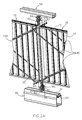
- Fig.2A is an exploded view of the sliding door arrangement of Fig.1
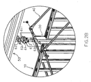
- Fig.2B is an enlarged view of portion A in Fig.2A .
- Fig.3 is a cross-sectional side view of Fig.1 .
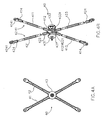
- Fig.4A is a schematic diagram illustrating a rod assembly used in the sliding door arrangement of Fig.1
- Fig.4B is an exploded view illustrating the parts of the rod assembly.
- the sliding door arrangement includes a plurality of door units 10, a plurality of upright posts 20, a lower beam 30, cross rod assemblies 40 and connectors 60.
- the sliding door arrangement may selectively include an upper beam 50.
- the door unit 10 is grid type, to be specific, the door unit 10 is a grid type part formed by connecting an outer frame 11 of aluminum profile and a plurality of vertical rods 12 of hollow aluminum tube which are arranged vertically and spaced apart from each other, and the door unit 10 can be packaged and transported separately.
- the sliding door arrangement 100 of the present invention is generally configured by connecting the door units by the plurality of the upright posts. Though only two door units are shown in Fig.1 and Fig.2 , the number of the door units is not limited to this; obviously, the number of the door units depends on the actual length and design requirements of the sliding door arrangement.
- the upright post 20 is a hollow tubular body of aluminum profile with a substantially rectangular cross section, the height of which is about the same as that of the sliding door arrangement.
- the upright post has positioning slots 21 on the right side and the left side, so that the right side and the left side of the door unit 10 can be positioned in these slots.
- the upright post 20 has an upper opening 22 and a lower opening 23 at the upper end and the lower end respectively to connect with the upper beam 50 and the lower beam 30.
- the upright post 20 has an upper connecting hole 24 near the upper end thereof for connecting the cross rod assembly to the upright post.
- the upright post 20 further has a lower connecting hole 25 near the lower end thereof for connecting the cross rod assembly to the upright post.
- an upper beam 50 which is a hollow tubular body of aluminum profile with U shape cross section, is mounted on the top of the sliding door arrangement 100.
- the upper beam 50 has connecting holes (not shown) on the lower sidewall at positions corresponding to the upright posts 20 in order to connect with the upright posts 20 through connectors 60.
- the lower beam 30 which is made of aluminum profile, with an approximately rectangular cross-section (also could be regarded as an inverted U shape cross-section), is mounted at the bottom of the sliding door arrangement 100.
- a spacer plate 33 which has an inverted T shape, is disposed in the lower beam near the upper portion thereof in order to increase the strength of the lower beam.
- the lower beam has two grooves on the top surface along the longitudinal direction, which are corresponding to a wall thickness of the outer frame 11 of the door units, so that the outer frame 11 of the plurality of door units 10 can be embedded and engaged in these grooves.
- the lower beam 30 has a plurality of connecting holes 32 on its top surface at positions corresponding to the upright posts 20 and connects with the upright posts 20 though connectors 60.
- the connector 60 includes a connecting sleeve 61, at least a connecting block 62 and several connecting bolts 63.
- the connecting sleeve 61 is in a rectangular shape conforming to the internal shape of the upright post 20 for inserting therein.
- the connecting sleeve 61 is made of plastic material.
- the connecting sleeve 61 includes an opening, a bottom and at least two sidewalls (not labeled). The opening faces to the upper opening 22 or the lower opening 23 of the upright post 20 when assembled.
- the bottom has a plurality of vertical connecting holes 611 thereon.
- the sidewalls have a plurality of horizontal connecting holes 612 thereon for connecting with the rods 41,42(below mentioned).
- the connecting sleeve for connecting the lower beam 30 is opened upward, while the connecting sleeve for connecting the upper beam 50 is opened downward.
- the connecting block 62 which is a plate like body has a plurality of threaded holes 621 corresponding to the plurality of vertical connecting holes 611 on the connecting sleeve 61.
- the connecting block 62 is disposed in the lower beam 30 or the upper beam 50 at the position corresponding to the upright post 20 respectively, where the connecting block in the lower beam 30 is mounted in the top portion inside of the lower beam, while the connecting block in the upper beam 50 is mounted at the bottom of the upper beam, and the connecting block is mounted into the upper beam or lower beam by a special fixture.
- one end of the connecting bolt 63 with a screw cap is disposed in the connecting sleeve 61, while the other end passes through the lower beam 30 or the lower beam 50 to threadedly connect with the connecting block 62, so that the lower beam 30 and the upper beam 50 could connect with the upright post.
- each door unit 10 is equipped with a pair of cross rod assemblies 40 on the front side and the rear side respectively to adjust the degree of tightness.
- the rod assembly as shown in Fig.1 , Fig.4A and Fig.4B , includes two rods 41, 42 and a center shaft assembly 43.
- the rods 41, 42 are formed by threadedly connecting several rod segments made of hollow tube.
- each of the rods 41, 42 is formed by threadedly connecting three rod segments 411, 412, 413 and 421, 422, 423 respectively.
- each of the rod segments 411, 413 and 421, 423 located at the edges have threaded portions with a smaller external diameter than an internal diameter of the rod segments 412 and 422 located at center.
- the revolving directions of the external threads at the two ends of each of the rod segments 411, 413 and 421, 422 are opposite, that is, if one end revolves to the left, then the other end revolves to the right.
- both ends of each of the rod segments 412, 412 located at the center have internal threads that revolve in the same direction as the external threads of the rod segments 411, 413 and 421, 423 and threadedly connect with them respectively.
- Rod segments 412, 422 have shaft holes 4121, 4221 respectively at the intersection of two rods 41, 42.
- both ends of each of rods 41, 42 are provided with adapters 414,424 respectively.
- the adapters 414 and 424 have rod connecting holes 4141 and 4241 respectively to connect with the upright post 20.
- the adapters 414 and 424 have internal threads that revolve in the same direction as the external threads of the rod segments 411, 413 and 421, 423 and threadedly connect with them respectively.
- the rods 41, 42 are diagonally connected on the side surface of each door unit, the upper end and the lower end of each of the rods 41, 42 connecting with the upright posts 20 by a shaft pin 44 passing through the rod connecting holes 4141, 4241 and the upper connecting hole 24 and lower connecting hole 25 of the upright post.
- the center shaft assembly 43 is rotatablely connected at the intersection of two rods.
- the center shaft assembly 43 as shown in Fig 4A and Fig.4B , includes a center shaft 431, a front shaft seat 432 and a rear shaft seat 433, wherein, the front shaft seat 432 and the rear shaft seat 433 are in cover shape with shaft holes, and function to support and decorate the center shaft.
- a shaft sleeve 4331 is disposed in the rear shaft seat 433 and passes through the shaft holes 4121, 4221.
- the center shaft 431 passes through the front shaft seat 432 and the shaft sleeve 4331 of the rear shaft seat 433 and is fixed by at least a bolt, so that the rods 41, 42 can rotate around the center shaft 431.
- the degree of tightness of the rods 41, 42 is adjustable. When adjusting, clamp any of the rod segments 411, 413 and 421, 423 of the rods 41 or 42 with a specific tool and rotate to simultaneously tighten or release the rods 41 or 42 to a suitable degree of tightness.
Landscapes
- Engineering & Computer Science (AREA)
- Civil Engineering (AREA)
- Structural Engineering (AREA)
- Gates (AREA)
- Rigid Containers With Two Or More Constituent Elements (AREA)
- Wing Frames And Configurations (AREA)
- Buffer Packaging (AREA)
- Packaging Of Annular Or Rod-Shaped Articles, Wearing Apparel, Cassettes, Or The Like (AREA)
Claims (11)
- Agencement de porte coulissante (100) comprenant :une pluralité d'unités de porte (10),au moins un montant droit (20) reliant deux unités de porte adjacentes (10),une solive inférieure (30), située sur une partie basse du montant droit (20) et reliée à celle-ci etune pluralité d'ensembles de tiges croisées (40) disposées respectivement sur un côté ou des deux ôtés de chacune des unités de porte (10) pour ajuster une étanchéité de l'agencement de porte coulissante (100).
- Agencement de porte coulissante (100) selon la revendication 1 dans lequel les unités de porte (10) sont de type grille.
- Agencement de porte coulissante (100) selon la revendication 2 dans lequel les unités de porte (10) sont formées en reliant un cadre extérieur (11) et une pluralité de tiges verticales (12) qui sont arrangées verticalement et espacées
- Agencement de porte coulissante (100) selon la revendication 3 dans lequel l'agencement de porte coulissante (100) comprend de plus :une solive supérieure (50) située sur une partie supérieure de l'agencement de porte coulissante (100) etune pluralité de connecteurs (60) reliant respectivement la solive inférieure (30), la solive supérieure (50) et l'ensemble de tiges croisées (40) au montant debout (20).
- Agencement de porte coulissante (100) selon la revendication 4 dans lequel le montant debout (20) est creux dans un centre de celui-ci et comprend :une pluralité de fentes de positionnement (21) définies sur le côté droit et le côté gauche du montant debout (20) pour s'engrener avec des unités de porte respectives (10) ;un trou de liaison supérieur (25) près de l'extrémité supérieure du montant debout (20) pour relier l'ensemble de tiges croisées (40) à celui-ci ;un trou de liaison inférieur (24) près de l'extrémité inférieure du montant debout (20) pour relier l'ensemble de tiges croisées (40) à celui-ci ;une ouverture supérieure (22) à l'extrémité supérieure du montant debout (20) pour relier la solive supérieure (50) à celui-ci ;une ouverture inférieure (23) à l'extrémité inférieure du montant debout (20) pour relier la solive inférieure (30) à celui-ci.
- Agencement de porte coulissante (100) selon la revendication 5 dans lequel la solive inférieure (30) a généralement une section transversale en forme de U renversé et comprend :une rainure sur sa surface de dessus le long du sens longitudinal pour s'engrener avec l'unité de porte etune pluralité de trous de liaison (32) disposés en correspondant à la position du montant debout (20) pour relier la solive inférieure (30) au montant debout (20).
- Agencement de porte coulissante (100) selon la revendication 6 dans lequel le connecteur (60) comprend :une pluralité de manchons de liaison (61) avec une forme conforme à la forme intérieure du montant debout (20) pour s'y insérer, les manchons de liaison (61) comprenant :une ouverture en face de l'ouverture supérieure (22) ou de l'ouverture inférieure (23) du montant debout (20) lorsqu'il est assemblé ;un fond ayant une pluralité de trous de liaison verticaux (611) sur celui-ci, au moins deux parois latérales ayant une pluralité de trous de liaison horizontaux (612) dessus pour la liaison avec des tiges,une pluralité de blocs de liaison (62), disposés respectivement dans la solive supérieure (50) et la solive inférieure (30) correspondant aux positions des manchons de liaison (61) et ayant une pluralité de trous filetés (621) dessus correspondant à la pluralité de trous de liaison verticaux (611) des manchons de liaison (61) etune pluralité de boulons de liaison (63), chacun avec une extrémité disposée dans un manchon de liaison correspondant (61) et l'autre extrémité reliée par un filet au bloc de liaison (62) respectivement à travers la solive inférieure (30) ou la solive supérieure (50) si bien que la solive inférieure (30) et la solive supérieure (50) sont reliées au montant debout (20).
- Agencement de porte coulissante (100) selon la revendication 7 dans lequel chacun des ensembles de tiges croisées (40) comprend :deux tiges (41, 42) disposées sensiblement diagonalement sur la surface latérale de chaque unité de porte etun ensemble d'arbre central (43) pour relier en rotation les deux tiges (41, 42) ensemble à l'intersection,dans lequel les deux extrémités de chaque tige (41, 42) ont un trou de liaison de tige (4141, 4241) et les tiges (41, 42) sont reliées au montant droit (20) par une tige à broche ou un boulon, la tige à broche ou le boulon traversant respectivement les trous de liaison de tige (4141, 4241) et le trou de liaison supérieur (25) et le trou de liaison inférieur (24) du montant debout (20), chacune des deux tiges (41, 42) ayant un trou de tige (4121, 4221) à une intersection de deux tiges (41, 42).
- Agencement de porte coulissante (100) selon la revendication 1 dans lequel chacun des ensembles de tiges croisées (40) comprend :deux tiges (41, 42) disposées sensiblement diagonalement sur la surface latérale de chaque unité de porte, les deux extrémités de chaque tige (41, 42) reliées au montant droit (20) etun ensemble d'arbre central (43) pour relier en rotation les deux tiges (41, 42) ensemble à une intersection des deux tiges (41, 42),dans lequel chacune des tiges (41, 42) consiste en plusieurs segments de tige (411, 412, 413, 421, 422, 423) reliés par un filet et chacun des sens de rotation des segments de tige (411, 412, 413, 421, 422, 423) est configuré tel que l'étanchéité de l'agencement de porte coulissante (100) pourrait être ajusté en faisant tourner les segments de tige (411, 412, 413, 421, 422, 423) correspondants.
- Agencement de porte coulissante (100) selon la revendication 9 dans lequel l'ensemble d'arbre central (43) comprend :un arbre central (431),un siège d'arbre antérieur (432) etun siège d'arbre postérieur (433) avec un manchon d'arbre (4331), le siège d'arbre antérieur (432) et le siège d'arbre postérieur (433) étant en forme de couvercle avec des trous d'arbre (4121, 4221) et fonctionnant pour supporter et décorer l'arbre central (431),dans lequel le manchon d'arbre (4331) traverse les trous d'arbre (4121, 4221) et l'arbre central (431) traverse le siège d'arbre antérieur (432) et le manchon d'arbre (4331) du siège d'arbre postérieur (433) et est fixé par au moins un boulon si bien que les tiges (41, 42) pourraient tourner autour de l'arbre central (431)
- Agencement de porte coulissante (100) selon la revendication 1 dans lequel :les unités de porte (10) sont de type grille,le montant debout qui existe au moins (20) est creux en son centre,dans lequel le montant debout (20) comprend :une pluralité de fentes de positionnement (21) sur le côté droit et sur le côté gauche de celui-ci pour s'engrener avec des unités de porte respectives (10),un trou de liaison supérieur (25) près de l'extrémité supérieure de celui-ci pour relier l'ensemble de tiges croisées (40) au montant debout (20),un trou de liaison inférieur (23) près de l'extrémité inférieure de celui-ci pour relier l'ensemble de tiges croisées (40) au montant debout (20),une ouverture inférieure (23) à l'extrémité inférieure de celui-ci pour relier le montant debout (20) à la solive inférieure (30) etune pluralité de connecteurs (60) reliant la solive inférieure (30) et l'ensemble de tiges croisées (40) au montant debout (20),dans lequel chacun des ensembles de tiges croisées (40) comprend :deux tiges (41, 42) disposées sensiblement en diagonale sur la surface latérale de chaque unité de porte, deux extrémités de chaque tige (41, 42) reliées au montant debout (20) etun ensemble d'arbre central (43) pour relier en rotation les deux tiges (41, 42) ensemble à une intersection des deux tiges (41, 42).
Applications Claiming Priority (1)
| Application Number | Priority Date | Filing Date | Title |
|---|---|---|---|
| CN2008100662571A CN101260781B (zh) | 2008-03-28 | 2008-03-28 | 平移门的门体结构 |
Publications (3)
| Publication Number | Publication Date |
|---|---|
| EP2105573A2 EP2105573A2 (fr) | 2009-09-30 |
| EP2105573A3 EP2105573A3 (fr) | 2011-06-22 |
| EP2105573B1 true EP2105573B1 (fr) | 2012-08-01 |
Family
ID=39961441
Family Applications (1)
| Application Number | Title | Priority Date | Filing Date |
|---|---|---|---|
| EP08172333A Active EP2105573B1 (fr) | 2008-03-28 | 2008-12-19 | Agencement de porte coulissante |
Country Status (4)
| Country | Link |
|---|---|
| US (1) | US7891152B2 (fr) |
| EP (1) | EP2105573B1 (fr) |
| CN (1) | CN101260781B (fr) |
| AU (1) | AU2008258172B2 (fr) |
Cited By (1)
| Publication number | Priority date | Publication date | Assignee | Title |
|---|---|---|---|---|
| DE102014103365A1 (de) * | 2014-03-12 | 2015-09-17 | G & Z - Alu-Systeme Gmbh | Schiebetor |
Families Citing this family (15)
| Publication number | Priority date | Publication date | Assignee | Title |
|---|---|---|---|---|
| JP2010188896A (ja) * | 2009-02-19 | 2010-09-02 | Nabtesco Corp | ホームドア装置 |
| CN101503937B (zh) * | 2009-03-10 | 2011-12-07 | 深圳市红门科技股份有限公司 | 平移门的门框式机箱 |
| CA2665960C (fr) * | 2009-05-14 | 2011-07-26 | Technostructur Inc. | Module de paroi, module d'habitation et immeuble construit a l'aide de tels modules de paroi |
| FR2947299B1 (fr) * | 2009-06-26 | 2017-05-12 | Dirickx Groupe | Systeme pour l'obstruction d'un passage d'entree a l'aide d'un vantail roulant sur une surface plane, comprenant des moyens de guidage fin de course du vantail |
| AP2012006381A0 (en) * | 2009-12-18 | 2012-08-31 | Patco Llc | Panelized structural system for building construction |
| CN102287131A (zh) * | 2011-07-27 | 2011-12-21 | 无锡帝安福科技有限公司 | 组装式悬臂门 |
| CN104110209B (zh) * | 2014-07-02 | 2016-01-06 | 佛山市掌门人智能科技有限公司 | 一种平移门 |
| US20160130824A1 (en) * | 2016-01-14 | 2016-05-12 | Teng-Wei Chang | Safe scaffold structure with guardrails |
| AT521487B1 (de) * | 2018-10-17 | 2020-02-15 | Wakonig Martin | Vorrichtung zur vertikalen Anbringung an einer Wand |
| CN110265905B (zh) * | 2019-05-09 | 2020-12-15 | 贵州电网有限责任公司 | 一种变压器辅助检修系统 |
| US11725413B2 (en) * | 2020-07-17 | 2023-08-15 | Granite Industries, Inc. | Elevated flooring system for clearspan tent |
| CN112112260B (zh) * | 2020-09-22 | 2022-02-08 | 四川中物裕邦科技有限公司 | 一种安检门连接结构 |
| US20240328176A1 (en) * | 2023-03-29 | 2024-10-03 | ScaffoldMart | Breakdown Safety Rail System for Scaffold |
| WO2025042678A1 (fr) * | 2023-08-18 | 2025-02-27 | Wayne State University | Paroi-structure hybride de grande capacité destinée à une construction d'acier formée à froid |
| EP4786724A1 (fr) | 2023-09-01 | 2026-08-05 | M.C. Garcia Importaciones y Exportaciones Limitada | Portail portable et assemblable, industrialisé et standardisé pour un utilisateur final avec ou sans l'aide d'un installateur |
Family Cites Families (30)
| Publication number | Priority date | Publication date | Assignee | Title |
|---|---|---|---|---|
| US515340A (en) * | 1894-02-27 | Adelbert f | ||
| US202722A (en) * | 1878-04-23 | Improvement in portable fences | ||
| US618619A (en) * | 1899-01-31 | Henry j | ||
| US2732919A (en) * | 1956-01-31 | johnson | ||
| US1114479A (en) * | 1914-01-14 | 1914-10-20 | Henry Iven | Portable fence. |
| US1235152A (en) * | 1916-04-26 | 1917-07-31 | Swan Allen Nelson | Adjustable screen-door. |
| US1233719A (en) * | 1916-10-09 | 1917-07-17 | Jay Benjamin Franklin Showalter | Gate. |
| US1298072A (en) * | 1918-10-25 | 1919-03-25 | James R Mcnabney | Gate. |
| US1923961A (en) * | 1930-04-14 | 1933-08-22 | Albert E Wood | Apparatus for reenforcing doors |
| US2144528A (en) * | 1936-07-24 | 1939-01-17 | Young Radiator Co | Grille and method of making same |
| US2434447A (en) * | 1946-02-14 | 1948-01-13 | Perry E Van Horn | Gate |
| US2597786A (en) * | 1949-05-14 | 1952-05-20 | Raymond L Fontaine | Garage door |
| US2686579A (en) * | 1950-03-08 | 1954-08-17 | Johannsen & Taylor Inc | Frameless garage door |
| US3367080A (en) * | 1965-10-23 | 1968-02-06 | Automatic Sprinkler Corp | Adjustable cross brace |
| US4083535A (en) * | 1976-10-28 | 1978-04-11 | Britt James O | Portable fence |
| US4167088A (en) * | 1978-07-06 | 1979-09-11 | Peachtree Doors, Inc. | Doors for patios and the like |
| US4618067A (en) * | 1982-03-04 | 1986-10-21 | Metropolitan Wire Corporation | Surgical case cart |
| NL8302007A (nl) * | 1983-06-06 | 1985-01-02 | Heras Holding | Poort. |
| US4628638A (en) * | 1985-07-19 | 1986-12-16 | International Gate Devices, Inc. | Cantilever-type slide gate |
| US4723374A (en) * | 1986-01-15 | 1988-02-09 | The Tymetal Corporation, Inc. | Cantilevered sliding gate |
| US5022185A (en) * | 1990-01-25 | 1991-06-11 | Oatman Dean K | Gate pulley guard |
| US5136813A (en) * | 1991-09-23 | 1992-08-11 | Fence Hardware Specialties, Inc. Dba Ameristar Fence Products | Cantilever-type sliding gate |
| US5279088A (en) * | 1992-01-17 | 1994-01-18 | Heydon Building Systems International, Limited | Wall structure and method of forming the same |
| ES2219222T3 (es) * | 1993-12-20 | 2004-12-01 | R.A.R. Consultants Ltd. | Fijacion de unselemento arquitectonico de acabado. |
| US5575321A (en) * | 1995-02-07 | 1996-11-19 | Currier; Ken E. | Security door system for sliding screen doors |
| US6192637B1 (en) * | 1999-02-25 | 2001-02-27 | Kenneth T. Boilen | Moveable structural reinforcement system |
| US20020129569A1 (en) * | 2001-02-26 | 2002-09-19 | Collins Steven K. | Insta French |
| CA2350419C (fr) * | 2001-06-14 | 2006-12-12 | Camco Inc. | Porte thermique et renforcee de refrigerateur |
| US6941718B1 (en) * | 2002-01-28 | 2005-09-13 | The Steel Network, Inc. | Wall structure |
| SE521073C2 (sv) * | 2002-10-11 | 2003-09-30 | Gunnebo Perimeter Prot Ab | Anordning vid port |
-
2008
- 2008-03-28 CN CN2008100662571A patent/CN101260781B/zh active Active
- 2008-11-26 US US12/323,962 patent/US7891152B2/en active Active
- 2008-12-18 AU AU2008258172A patent/AU2008258172B2/en active Active
- 2008-12-19 EP EP08172333A patent/EP2105573B1/fr active Active
Cited By (2)
| Publication number | Priority date | Publication date | Assignee | Title |
|---|---|---|---|---|
| DE102014103365A1 (de) * | 2014-03-12 | 2015-09-17 | G & Z - Alu-Systeme Gmbh | Schiebetor |
| DE102014103365B4 (de) * | 2014-03-12 | 2015-12-03 | G & Z - Alu-Systeme Gmbh | Schiebetor |
Also Published As
| Publication number | Publication date |
|---|---|
| AU2008258172A1 (en) | 2009-10-15 |
| CN101260781A (zh) | 2008-09-10 |
| CN101260781B (zh) | 2011-01-12 |
| EP2105573A3 (fr) | 2011-06-22 |
| EP2105573A2 (fr) | 2009-09-30 |
| US20090241427A1 (en) | 2009-10-01 |
| US7891152B2 (en) | 2011-02-22 |
| AU2008258172B2 (en) | 2012-04-26 |
Similar Documents
| Publication | Publication Date | Title |
|---|---|---|
| US7891152B2 (en) | Sliding door arrangement | |
| US8714229B2 (en) | Hydraulic leveraged overhead door assembly | |
| DE102009022479B4 (de) | Mobiles modulares Wandsystem | |
| US20030019167A1 (en) | Fast mounted building unit | |
| CN201411783Y (zh) | 方便拆装的箱式组合房 | |
| CN211714015U (zh) | 建造于地下空间的房建结构 | |
| CN115522631B (zh) | 一种旋转滑块式模块钢结构节点及其施工方法 | |
| US11686148B2 (en) | Leg for a frame of an overhead door assembly | |
| JP2012132198A (ja) | 手摺 | |
| CN209586048U (zh) | 平开门及其转轴机构 | |
| CN101949187A (zh) | 一种单元式幕墙三维调节定位的受力装置 | |
| KR200311206Y1 (ko) | 분해조립형 컨테이너 | |
| CN115233885B (zh) | 一种活动板房屋顶支撑结构 | |
| CN215442578U (zh) | 一种便于安装的铝制幕墙结构 | |
| AU2003227052A1 (en) | Supporting and guiding device for holding movable, hanging door or wall elements | |
| CN215758686U (zh) | 全高转闸 | |
| CN213143515U (zh) | 一种加强筋可调整方位的铝单板 | |
| CN118881077B (zh) | 一种模块化玻璃幕墙施工方法 | |
| KR20150001915A (ko) | 다수개의 판넬로 조립구성된 출입구 개폐용 문 | |
| CN223893860U (zh) | 一种多用途可伸缩建筑施工洞口防护设施 | |
| CN205857902U (zh) | 一种罗马柱形状无螺丝快装帐篷 | |
| CN110821172A (zh) | 一种建筑支模用收折式支撑架 | |
| CN220301589U (zh) | 一种新型曲面幕墙 | |
| CN211900025U (zh) | 一种房建施工可调节式防护栏 | |
| JP3151194U (ja) | クロスゲート |
Legal Events
| Date | Code | Title | Description |
|---|---|---|---|
| PUAI | Public reference made under article 153(3) epc to a published international application that has entered the european phase |
Free format text: ORIGINAL CODE: 0009012 |
|
| AK | Designated contracting states |
Kind code of ref document: A2 Designated state(s): AT BE BG CH CY CZ DE DK EE ES FI FR GB GR HR HU IE IS IT LI LT LU LV MC MT NL NO PL PT RO SE SI SK TR |
|
| AX | Request for extension of the european patent |
Extension state: AL BA MK RS |
|
| 17P | Request for examination filed |
Effective date: 20091203 |
|
| PUAL | Search report despatched |
Free format text: ORIGINAL CODE: 0009013 |
|
| AK | Designated contracting states |
Kind code of ref document: A3 Designated state(s): AT BE BG CH CY CZ DE DK EE ES FI FR GB GR HR HU IE IS IT LI LT LU LV MC MT NL NO PL PT RO SE SI SK TR |
|
| AX | Request for extension of the european patent |
Extension state: AL BA MK RS |
|
| GRAP | Despatch of communication of intention to grant a patent |
Free format text: ORIGINAL CODE: EPIDOSNIGR1 |
|
| AKX | Designation fees paid |
Designated state(s): AT BE BG CH CY CZ DE DK EE ES FI FR GB GR HR HU IE IS IT LI LT LU LV MC MT NL NO PL PT RO SE SI SK TR |
|
| GRAS | Grant fee paid |
Free format text: ORIGINAL CODE: EPIDOSNIGR3 |
|
| GRAA | (expected) grant |
Free format text: ORIGINAL CODE: 0009210 |
|
| AK | Designated contracting states |
Kind code of ref document: B1 Designated state(s): AT BE BG CH CY CZ DE DK EE ES FI FR GB GR HR HU IE IS IT LI LT LU LV MC MT NL NO PL PT RO SE SI SK TR |
|
| REG | Reference to a national code |
Ref country code: GB Ref legal event code: FG4D |
|
| REG | Reference to a national code |
Ref country code: CH Ref legal event code: EP Ref country code: AT Ref legal event code: REF Ref document number: 568818 Country of ref document: AT Kind code of ref document: T Effective date: 20120815 |
|
| REG | Reference to a national code |
Ref country code: IE Ref legal event code: FG4D |
|
| REG | Reference to a national code |
Ref country code: DE Ref legal event code: R096 Ref document number: 602008017548 Country of ref document: DE Effective date: 20120927 |
|
| REG | Reference to a national code |
Ref country code: NL Ref legal event code: VDEP Effective date: 20120801 |
|
| REG | Reference to a national code |
Ref country code: CH Ref legal event code: PFA Owner name: HONGMEN ADVANCED TECHNOLOGY CORPORATION, CN Free format text: FORMER OWNER: SHENZHEN HONGMEN SCIENCE AND TECHNOLOGY CO., LTD., CN Ref country code: CH Ref legal event code: NV Representative=s name: LANGPATENT ANWALTSKANZLEI, CH |
|
| REG | Reference to a national code |
Ref country code: AT Ref legal event code: MK05 Ref document number: 568818 Country of ref document: AT Kind code of ref document: T Effective date: 20120801 |
|
| RAP2 | Party data changed (patent owner data changed or rights of a patent transferred) |
Owner name: HONGMEN ADVANCED TECHNOLOGY CORPORATION |
|
| REG | Reference to a national code |
Ref country code: LT Ref legal event code: MG4D Effective date: 20120801 |
|
| PG25 | Lapsed in a contracting state [announced via postgrant information from national office to epo] |
Ref country code: LT Free format text: LAPSE BECAUSE OF FAILURE TO SUBMIT A TRANSLATION OF THE DESCRIPTION OR TO PAY THE FEE WITHIN THE PRESCRIBED TIME-LIMIT Effective date: 20120801 Ref country code: NO Free format text: LAPSE BECAUSE OF FAILURE TO SUBMIT A TRANSLATION OF THE DESCRIPTION OR TO PAY THE FEE WITHIN THE PRESCRIBED TIME-LIMIT Effective date: 20121101 Ref country code: FI Free format text: LAPSE BECAUSE OF FAILURE TO SUBMIT A TRANSLATION OF THE DESCRIPTION OR TO PAY THE FEE WITHIN THE PRESCRIBED TIME-LIMIT Effective date: 20120801 Ref country code: AT Free format text: LAPSE BECAUSE OF FAILURE TO SUBMIT A TRANSLATION OF THE DESCRIPTION OR TO PAY THE FEE WITHIN THE PRESCRIBED TIME-LIMIT Effective date: 20120801 Ref country code: CY Free format text: LAPSE BECAUSE OF FAILURE TO SUBMIT A TRANSLATION OF THE DESCRIPTION OR TO PAY THE FEE WITHIN THE PRESCRIBED TIME-LIMIT Effective date: 20120801 Ref country code: IS Free format text: LAPSE BECAUSE OF FAILURE TO SUBMIT A TRANSLATION OF THE DESCRIPTION OR TO PAY THE FEE WITHIN THE PRESCRIBED TIME-LIMIT Effective date: 20121201 Ref country code: HR Free format text: LAPSE BECAUSE OF FAILURE TO SUBMIT A TRANSLATION OF THE DESCRIPTION OR TO PAY THE FEE WITHIN THE PRESCRIBED TIME-LIMIT Effective date: 20120801 |
|
| REG | Reference to a national code |
Ref country code: CH Ref legal event code: PCOW Free format text: NEW ADDRESS: HONGMEN INDUSTRY PARK SHANGXUE DUAN JIHUA ROAD, BUJI LONGGANG DISTRICT SHENZHEN, GUANGDONG 518129 (CN) |
|
| REG | Reference to a national code |
Ref country code: CH Ref legal event code: PCOW Free format text: NEW ADDRESS: HONGMEN INDUSTRY PARK SHANGXUE DUAN JIHUA ROAD, BUJI LONGGANG DISTRICT SHENZHEN, GUANGDONG 518129 (CN) |
|
| PG25 | Lapsed in a contracting state [announced via postgrant information from national office to epo] |
Ref country code: PL Free format text: LAPSE BECAUSE OF FAILURE TO SUBMIT A TRANSLATION OF THE DESCRIPTION OR TO PAY THE FEE WITHIN THE PRESCRIBED TIME-LIMIT Effective date: 20120801 Ref country code: SI Free format text: LAPSE BECAUSE OF FAILURE TO SUBMIT A TRANSLATION OF THE DESCRIPTION OR TO PAY THE FEE WITHIN THE PRESCRIBED TIME-LIMIT Effective date: 20120801 Ref country code: PT Free format text: LAPSE BECAUSE OF FAILURE TO SUBMIT A TRANSLATION OF THE DESCRIPTION OR TO PAY THE FEE WITHIN THE PRESCRIBED TIME-LIMIT Effective date: 20121203 Ref country code: SE Free format text: LAPSE BECAUSE OF FAILURE TO SUBMIT A TRANSLATION OF THE DESCRIPTION OR TO PAY THE FEE WITHIN THE PRESCRIBED TIME-LIMIT Effective date: 20120801 Ref country code: LV Free format text: LAPSE BECAUSE OF FAILURE TO SUBMIT A TRANSLATION OF THE DESCRIPTION OR TO PAY THE FEE WITHIN THE PRESCRIBED TIME-LIMIT Effective date: 20120801 Ref country code: BE Free format text: LAPSE BECAUSE OF FAILURE TO SUBMIT A TRANSLATION OF THE DESCRIPTION OR TO PAY THE FEE WITHIN THE PRESCRIBED TIME-LIMIT Effective date: 20120801 Ref country code: GR Free format text: LAPSE BECAUSE OF FAILURE TO SUBMIT A TRANSLATION OF THE DESCRIPTION OR TO PAY THE FEE WITHIN THE PRESCRIBED TIME-LIMIT Effective date: 20121102 |
|
| PG25 | Lapsed in a contracting state [announced via postgrant information from national office to epo] |
Ref country code: NL Free format text: LAPSE BECAUSE OF FAILURE TO SUBMIT A TRANSLATION OF THE DESCRIPTION OR TO PAY THE FEE WITHIN THE PRESCRIBED TIME-LIMIT Effective date: 20120801 |
|
| PG25 | Lapsed in a contracting state [announced via postgrant information from national office to epo] |
Ref country code: CZ Free format text: LAPSE BECAUSE OF FAILURE TO SUBMIT A TRANSLATION OF THE DESCRIPTION OR TO PAY THE FEE WITHIN THE PRESCRIBED TIME-LIMIT Effective date: 20120801 Ref country code: ES Free format text: LAPSE BECAUSE OF FAILURE TO SUBMIT A TRANSLATION OF THE DESCRIPTION OR TO PAY THE FEE WITHIN THE PRESCRIBED TIME-LIMIT Effective date: 20121112 Ref country code: EE Free format text: LAPSE BECAUSE OF FAILURE TO SUBMIT A TRANSLATION OF THE DESCRIPTION OR TO PAY THE FEE WITHIN THE PRESCRIBED TIME-LIMIT Effective date: 20120801 Ref country code: DK Free format text: LAPSE BECAUSE OF FAILURE TO SUBMIT A TRANSLATION OF THE DESCRIPTION OR TO PAY THE FEE WITHIN THE PRESCRIBED TIME-LIMIT Effective date: 20120801 Ref country code: RO Free format text: LAPSE BECAUSE OF FAILURE TO SUBMIT A TRANSLATION OF THE DESCRIPTION OR TO PAY THE FEE WITHIN THE PRESCRIBED TIME-LIMIT Effective date: 20120801 |
|
| REG | Reference to a national code |
Ref country code: DE Ref legal event code: R082 Ref document number: 602008017548 Country of ref document: DE Representative=s name: LANGPATENT ANWALTSKANZLEI IP LAW FIRM, DE |
|
| PG25 | Lapsed in a contracting state [announced via postgrant information from national office to epo] |
Ref country code: SK Free format text: LAPSE BECAUSE OF FAILURE TO SUBMIT A TRANSLATION OF THE DESCRIPTION OR TO PAY THE FEE WITHIN THE PRESCRIBED TIME-LIMIT Effective date: 20120801 |
|
| PLBE | No opposition filed within time limit |
Free format text: ORIGINAL CODE: 0009261 |
|
| STAA | Information on the status of an ep patent application or granted ep patent |
Free format text: STATUS: NO OPPOSITION FILED WITHIN TIME LIMIT |
|
| 26N | No opposition filed |
Effective date: 20130503 |
|
| PG25 | Lapsed in a contracting state [announced via postgrant information from national office to epo] |
Ref country code: BG Free format text: LAPSE BECAUSE OF FAILURE TO SUBMIT A TRANSLATION OF THE DESCRIPTION OR TO PAY THE FEE WITHIN THE PRESCRIBED TIME-LIMIT Effective date: 20121101 Ref country code: MC Free format text: LAPSE BECAUSE OF NON-PAYMENT OF DUE FEES Effective date: 20121231 |
|
| REG | Reference to a national code |
Ref country code: DE Ref legal event code: R097 Ref document number: 602008017548 Country of ref document: DE Effective date: 20130503 |
|
| REG | Reference to a national code |
Ref country code: IE Ref legal event code: MM4A |
|
| PG25 | Lapsed in a contracting state [announced via postgrant information from national office to epo] |
Ref country code: IE Free format text: LAPSE BECAUSE OF NON-PAYMENT OF DUE FEES Effective date: 20121219 |
|
| PG25 | Lapsed in a contracting state [announced via postgrant information from national office to epo] |
Ref country code: MT Free format text: LAPSE BECAUSE OF FAILURE TO SUBMIT A TRANSLATION OF THE DESCRIPTION OR TO PAY THE FEE WITHIN THE PRESCRIBED TIME-LIMIT Effective date: 20120801 |
|
| PG25 | Lapsed in a contracting state [announced via postgrant information from national office to epo] |
Ref country code: TR Free format text: LAPSE BECAUSE OF FAILURE TO SUBMIT A TRANSLATION OF THE DESCRIPTION OR TO PAY THE FEE WITHIN THE PRESCRIBED TIME-LIMIT Effective date: 20120801 |
|
| PG25 | Lapsed in a contracting state [announced via postgrant information from national office to epo] |
Ref country code: HU Free format text: LAPSE BECAUSE OF FAILURE TO SUBMIT A TRANSLATION OF THE DESCRIPTION OR TO PAY THE FEE WITHIN THE PRESCRIBED TIME-LIMIT Effective date: 20081219 |
|
| REG | Reference to a national code |
Ref country code: DE Ref legal event code: R082 Ref document number: 602008017548 Country of ref document: DE Representative=s name: LANGPATENT ANWALTSKANZLEI IP LAW FIRM, DE Ref country code: DE Ref legal event code: R081 Ref document number: 602008017548 Country of ref document: DE Owner name: HONGMEN ADVANCED TECHNOLOGY CORPORATION, CN Free format text: FORMER OWNER: SHENZHEN HONGMEN SCIENCE & TECHNOLOGY CO., LTD., GUANGDONG, CN |
|
| REG | Reference to a national code |
Ref country code: FR Ref legal event code: PLFP Year of fee payment: 8 |
|
| REG | Reference to a national code |
Ref country code: CH Ref legal event code: PCAR Free format text: NEW ADDRESS: C/O CHRISTIAN LANG TAEAETSCHESTRASSE 38 POSTFACH 454, 3914 BLATTEN B. NATERS (CH) |
|
| REG | Reference to a national code |
Ref country code: FR Ref legal event code: PLFP Year of fee payment: 9 |
|
| REG | Reference to a national code |
Ref country code: FR Ref legal event code: PLFP Year of fee payment: 10 |
|
| REG | Reference to a national code |
Ref country code: CH Ref legal event code: U11 Free format text: ST27 STATUS EVENT CODE: U-0-0-U10-U11 (AS PROVIDED BY THE NATIONAL OFFICE) Effective date: 20260108 |
|
| PGFP | Annual fee paid to national office [announced via postgrant information from national office to epo] |
Ref country code: GB Payment date: 20251229 Year of fee payment: 18 |
|
| PGFP | Annual fee paid to national office [announced via postgrant information from national office to epo] |
Ref country code: LU Payment date: 20251229 Year of fee payment: 18 Ref country code: FR Payment date: 20251230 Year of fee payment: 18 |
|
| PGFP | Annual fee paid to national office [announced via postgrant information from national office to epo] |
Ref country code: DE Payment date: 20260127 Year of fee payment: 18 |
|
| PGFP | Annual fee paid to national office [announced via postgrant information from national office to epo] |
Ref country code: IT Payment date: 20251224 Year of fee payment: 18 |
|
| PGFP | Annual fee paid to national office [announced via postgrant information from national office to epo] |
Ref country code: CH Payment date: 20260108 Year of fee payment: 18 |