EP2105580A1 - Tuyère de turbine refroidie à refroidissement hybride - Google Patents
Tuyère de turbine refroidie à refroidissement hybride Download PDFInfo
- Publication number
- EP2105580A1 EP2105580A1 EP09155388A EP09155388A EP2105580A1 EP 2105580 A1 EP2105580 A1 EP 2105580A1 EP 09155388 A EP09155388 A EP 09155388A EP 09155388 A EP09155388 A EP 09155388A EP 2105580 A1 EP2105580 A1 EP 2105580A1
- Authority
- EP
- European Patent Office
- Prior art keywords
- cavity
- turbine
- mid
- impingement
- radially
- Prior art date
- Legal status (The legal status is an assumption and is not a legal conclusion. Google has not performed a legal analysis and makes no representation as to the accuracy of the status listed.)
- Granted
Links
- 238000001816 cooling Methods 0.000 claims abstract description 43
- 238000004891 communication Methods 0.000 claims abstract description 7
- 239000012530 fluid Substances 0.000 claims abstract description 5
- 238000000034 method Methods 0.000 claims description 12
- 238000010926 purge Methods 0.000 claims description 7
- 230000002093 peripheral effect Effects 0.000 claims description 3
- 239000007789 gas Substances 0.000 description 20
- 239000000567 combustion gas Substances 0.000 description 3
- 238000013461 design Methods 0.000 description 2
- 238000011144 upstream manufacturing Methods 0.000 description 2
- 238000003491 array Methods 0.000 description 1
- 238000005266 casting Methods 0.000 description 1
- 238000010276 construction Methods 0.000 description 1
- 230000008602 contraction Effects 0.000 description 1
- 238000005516 engineering process Methods 0.000 description 1
- 239000000446 fuel Substances 0.000 description 1
- 238000012986 modification Methods 0.000 description 1
- 230000004048 modification Effects 0.000 description 1
- 238000007789 sealing Methods 0.000 description 1
- 238000012546 transfer Methods 0.000 description 1
- 238000003466 welding Methods 0.000 description 1
Images


Classifications
-
- F—MECHANICAL ENGINEERING; LIGHTING; HEATING; WEAPONS; BLASTING
- F01—MACHINES OR ENGINES IN GENERAL; ENGINE PLANTS IN GENERAL; STEAM ENGINES
- F01D—NON-POSITIVE DISPLACEMENT MACHINES OR ENGINES, e.g. STEAM TURBINES
- F01D5/00—Blades; Blade-carrying members; Heating, heat-insulating, cooling or antivibration means on the blades or the members
- F01D5/12—Blades
- F01D5/14—Form or construction
- F01D5/18—Hollow blades, i.e. blades with cooling or heating channels or cavities; Heating, heat-insulating or cooling means on blades
- F01D5/187—Convection cooling
- F01D5/188—Convection cooling with an insert in the blade cavity to guide the cooling fluid, e.g. forming a separation wall
- F01D5/189—Convection cooling with an insert in the blade cavity to guide the cooling fluid, e.g. forming a separation wall the insert having a tubular cross-section, e.g. airfoil shape
-
- F—MECHANICAL ENGINEERING; LIGHTING; HEATING; WEAPONS; BLASTING
- F05—INDEXING SCHEMES RELATING TO ENGINES OR PUMPS IN VARIOUS SUBCLASSES OF CLASSES F01-F04
- F05D—INDEXING SCHEME FOR ASPECTS RELATING TO NON-POSITIVE-DISPLACEMENT MACHINES OR ENGINES, GAS-TURBINES OR JET-PROPULSION PLANTS
- F05D2260/00—Function
- F05D2260/20—Heat transfer, e.g. cooling
- F05D2260/201—Heat transfer, e.g. cooling by impingement of a fluid
-
- F—MECHANICAL ENGINEERING; LIGHTING; HEATING; WEAPONS; BLASTING
- F05—INDEXING SCHEMES RELATING TO ENGINES OR PUMPS IN VARIOUS SUBCLASSES OF CLASSES F01-F04
- F05D—INDEXING SCHEME FOR ASPECTS RELATING TO NON-POSITIVE-DISPLACEMENT MACHINES OR ENGINES, GAS-TURBINES OR JET-PROPULSION PLANTS
- F05D2260/00—Function
- F05D2260/20—Heat transfer, e.g. cooling
- F05D2260/202—Heat transfer, e.g. cooling by film cooling
-
- Y—GENERAL TAGGING OF NEW TECHNOLOGICAL DEVELOPMENTS; GENERAL TAGGING OF CROSS-SECTIONAL TECHNOLOGIES SPANNING OVER SEVERAL SECTIONS OF THE IPC; TECHNICAL SUBJECTS COVERED BY FORMER USPC CROSS-REFERENCE ART COLLECTIONS [XRACs] AND DIGESTS
- Y02—TECHNOLOGIES OR APPLICATIONS FOR MITIGATION OR ADAPTATION AGAINST CLIMATE CHANGE
- Y02T—CLIMATE CHANGE MITIGATION TECHNOLOGIES RELATED TO TRANSPORTATION
- Y02T50/00—Aeronautics or air transport
- Y02T50/60—Efficient propulsion technologies, e.g. for aircraft
Definitions
- This invention relates generally to gas turbine engine turbines and more particularly to methods for cooling turbine nozzles of such engines.
- a gas turbine engine includes a turbomachinery core having a high pressure compressor, a combustor, and a high pressure or gas generator turbine in serial flow relationship.
- the core is operable in a known manner to generate a primary gas flow.
- the core exhaust gas is directed through an exhaust nozzle to generate thrust.
- a turboshaft engine uses a low pressure or "work" turbine downstream of the core to extract energy from the primary flow to drive a shaft or other mechanical load.
- the gas generator turbine includes annular arrays of stationary vanes or nozzles that direct the gases exiting the combustor into rotating blades or buckets. Collectively one row of nozzles and one row of blades make up a "stage". Typically two or more stages are used in serial flow relationship. These components operate in an extremely high temperature environment, and must be cooled by air flow to ensure adequate service life. Typically, the air used for cooling is extracted from one or more points in the compressor. These bleed flows represent a loss of net work output and/or thrust to the thermodynamic cycle. They increase specific fuel consumption (SFC) and are generally to be avoided as much as possible.
- SFC specific fuel consumption
- Impingement is known to be a particularly effective cooling method and is frequently used in large turbine engines where the engine core flow is substantial.
- higher turbine stages in small turboshaft and turboprop engines stage do not typically employ impingement cooling of the airfoil because there is either not enough cooling air or enough supply pressure available.
- internal features like turbulators or pins provide the necessary convection heat transfer enhancements.
- the present invention provides a turbine nozzle cooled with a combination of impingement and convection cooling.
- a turbine nozzle for a gas turbine engine includes: (a) spaced-apart arcuate inner and outer bands; (b) a hollow, airfoil-shaped turbine vane extending between the inner and outer bands, the interior of the vane defining at least a forward cavity and a mid-cavity positioned aft of the forward cavity; (c) a hollow impingement insert received inside the mid-cavity, the impingement insert having walls which are pierced with at least one impingement cooling hole; (d) a passage in the turbine vane at a radially outer end of the forward cavity adapted to be coupled to a source of cooling air; and (e) a passage in the inner band in fluid communication with a radially inner end of the forward cavity and a radially inner end of the impingement insert.
- a method for cooling a turbine nozzle of a gas turbine engine which includes: spaced-apart arcuate inner and outer bands; a hollow, airfoil-shaped turbine vane extending between the inner and outer bands, the interior of the vane defining at least a forward cavity and a mid-cavity positioned aft of the forward cavity; and a hollow impingement insert received inside the mid-cavity, the impingement insert having walls which are pierced with at least one impingement cooling hole.
- the method includes: (a) supplying cooling air to the forward cavity at a radially outer end thereof; (b) subsequently passing at least a portion of the cooling air entering the forward cavity from a radially inner end of the forward cavity to the radially inner end of the impingement insert; and (c) ejecting cooling air through the impingement cooling holes to cool the mid-cavity.
- Figure 1 depicts a portion of a gas generator turbine 10, which is part of a gas turbine engine of a known type.
- the function of the gas generator turbine 10 is to extract energy from high-temperature, pressurized combustion gases from an upstream combustor (not shown) and to convert the energy to mechanical work, in a known manner.
- the gas generator turbine 10 drives an upstream compressor (not shown) through a shaft so as to supply pressurized air to the combustor.
- the engine is a turboshaft engine and a work turbine would be located downstream of the gas generator turbine 10 and coupled to an output shaft.
- a turboshaft engine and a work turbine would be located downstream of the gas generator turbine 10 and coupled to an output shaft.
- turboprop, turbojet, and turbofan engines as well as turbine engines used for other vehicles or in stationary applications.
- the gas generator turbine 10 includes a first stage nozzle 12 which comprises a plurality of circumferentially spaced airfoil-shaped hollow first stage vanes 14 that are supported between an arcuate, segmented first stage outer band 16 and an arcuate, segmented first stage inner band 18.
- the first stage vanes 14, first stage outer band 16 and first stage inner band 18 are arranged into a plurality of circumferentially adjoining nozzle segments that collectively form a complete 360° assembly.
- the first stage outer and inner bands 16 and 18 define the outer and inner radial flowpath boundaries, respectively, for the hot gas stream flowing through the first stage nozzle 12.
- the first stage vanes 14 are configured so as to optimally direct the combustion gases to a first stage rotor 20.
- the first stage rotor 20 includes a array of airfoil-shaped first stage turbine blades 22 extending outwardly from a first stage disk 24 that rotates about the centerline axis of the engine.
- a segmented, arcuate first stage shroud 26 is arranged so as to closely surround the first stage turbine blades 22 and thereby define the outer radial flowpath boundary for the hot gas stream flowing through the first stage rotor 20.
- a second stage nozzle 28 is positioned downstream of the first stage rotor 20, and comprises a plurality of circumferentially spaced airfoil-shaped hollow second stage vanes 30 that are supported between an arcuate, segmented second stage outer band 32 and an arcuate, segmented second stage inner band 34.
- the second stage vanes 30, second stage outer band 32 and second stage inner band 34 are arranged into a plurality of circumferentially adjoining nozzle segments 36 (see Figure 2 ) that collectively form a complete 360 0 assembly.
- the second stage outer and inner bands 32 and 34 define the outer and inner radial flowpath boundaries, respectively, for the hot gas stream flowing through the second stage turbine nozzle 34.
- the second stage vanes 30 are configured so as to optimally direct the combustion gases to a second stage rotor 38.
- the second stage rotor 38 includes a radial array of airfoil-shaped second stage turbine blades 40 extending radially outwardly from a second stage disk 42 that rotates about the centerline axis of the engine.
- a segmented arcuate second stage shroud 44 is arranged so as to closely surround the second stage turbine blades 40 and thereby define the outer radial flowpath boundary for the hot gas stream flowing through the second stage rotor 38.
- the segments of the first stage shroud 26 are supported by an array of arcuate first stage shroud hangers 46 that are in turn carried by an arcuate shroud support 48, for example using the illustrated hooks, rails, and C-clips in a known manner.
- the second stage nozzle 28 is supported in part by mechanical connections to the first stage shroud hangers 46 and the shroud support 48.
- Figures 2-4 illustrate the construction of the second stage nozzle 28 in more detail.
- Figure 2 shows an individual nozzle segment 36 which is a "singlet" casting. It incorporates a segment 50 of the outer band 32, a segment 52 of the inner band 34, and a hollow second stage vane 30.
- the interior of the second stage vane 30 is divided into a forward cavity 54, a mid-cavity 56, and a rear cavity 58.
- An impingement insert 60 is received in the mid-cavity 56.
- the radially outer end of the second stage vane 30 is closed by a cover 62.
- the cover 62 is a plate-like structure which has a lower peripheral edge 64 that mates with an opening 66 at the radially outer end of the second stage vane 30.
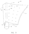
- FIG 3 shows the impingement insert 60 in more detail.
- the impingement insert 60 is a hollow, roughly airfoil-shaped structure, and has pressure and suction side walls 68 and 70 that extend between a leading edge 72 and a trailing edge 74.
- the impingement insert 60 is closed off by a tip wall 76 (see Figure 2 ) and a root wall 78.
- the walls of the impingement insert 60 are perforated by a plurality of impingement holes 80 of a known type which are sized to direct impingement jets against the walls of the mid-cavity 56.
- An inlet tube 82 with a closed distal end protrudes radially inward from the root wall 78.
- An inlet hole 84 is formed in the sidewall of the inlet tube 82.
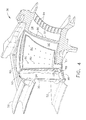
- FIG 4 shows in more detail how the impingement insert 60 is mounted in the second stage vane 30.
- the impingement insert 60 is received in the mid-cavity 56. Because the impingement insert 60 and the mid-cavity 56 both have larger cross-sectional areas at their outer ends than at their inner ends, the impingement insert 60 is installed from the outer end of the second stage vane 30. Its inner end is secured to the inner band segment 52, for example by a braze joint between the inlet tube 82 and the opening 87 in the inner band segment 52. Welding or mechanical fasteners could also be used in place of the brazed joint, with some means of sealing.
- the outer end of the impingement insert 60 is free to move radially in or out as a result of thermal expansion or contraction during operation.
- One or more pads or protrusions are provided as part of, or attached to, the impingement insert 60 and/or the walls of the mid-cavity 56 in order to locate the impingement insert and restrain its motion in the lateral and fore-and-aft directions.
- compressor discharge air at the highest pressure in the compressor, or another suitable cooling air flow, is ducted to a passage 83 at the radially outer end of the second stage vane 30. It then flows radially inward through the forward cavity 54 where it cools the turbine vane 30 by convection.
- heat-transfer-enhancing structures such as fins, pins, turbulence promoters (“turbulators”) may be provided in the forward cavity. A portion of the air exits the forward cavity through an purge hole 86 extending through the inner band segment 52.
- the purge hole 86 is sized such that about one-half of the mass flow entering the turbine vane 30 passes through the purge hole 86, and is used to purge the rotor cavity of the turbine 10.
- the remaining flow passes through a metering hole 88 and enters the impingement insert 60 through the inlet hole 84 in the inlet tube 82. It exits the impingement insert 60 through impingement holes 80 as jets that cool the mid-cavity 56.
- the air exits the mid-cavity 56 through crossover holes 90 in the wall 92 between the mid-cavity 56 and the rear cavity 58. It then cools the rear cavity 58 by convection.
- heat-transfer-enhancing structures such as fins, pins, turbulence promoters (“turbulators”) may be provided in the rear cavity 58.
- the spent cooling air exits the rear cavity 58 through trailing edge passages 94, such as the illustrated slots, or through film cooling holes (not shown) in the second stage vane 30.
- the turbine nozzle cooling configuration described herein is particularly useful when high pressure cooling air is available, but not in sufficient quantities to cool the entire nozzle with impingement.
- the design described herein combines turbulated lead edge cooling with mid-chord impingement and a warm bridge trailing edge to optimize the cooling and use of available air and pressure. The combination of these technologies enables a design that meets temperature goals which could not otherwise be met without higher cooling flow rates or extremely high turbulator enhancements.
Landscapes
- Engineering & Computer Science (AREA)
- Mechanical Engineering (AREA)
- General Engineering & Computer Science (AREA)
- Turbine Rotor Nozzle Sealing (AREA)
Applications Claiming Priority (1)
| Application Number | Priority Date | Filing Date | Title |
|---|---|---|---|
| US12/055,101 US8172504B2 (en) | 2008-03-25 | 2008-03-25 | Hybrid impingement cooled airfoil |
Publications (2)
| Publication Number | Publication Date |
|---|---|
| EP2105580A1 true EP2105580A1 (fr) | 2009-09-30 |
| EP2105580B1 EP2105580B1 (fr) | 2013-08-14 |
Family
ID=40833613
Family Applications (1)
| Application Number | Title | Priority Date | Filing Date |
|---|---|---|---|
| EP09155388.3A Ceased EP2105580B1 (fr) | 2008-03-25 | 2009-03-17 | Tuyère de turbine refroidie à refroidissement hybride |
Country Status (4)
| Country | Link |
|---|---|
| US (1) | US8172504B2 (fr) |
| EP (1) | EP2105580B1 (fr) |
| JP (1) | JP5546148B2 (fr) |
| CA (1) | CA2659489A1 (fr) |
Cited By (2)
| Publication number | Priority date | Publication date | Assignee | Title |
|---|---|---|---|---|
| EP2927428A1 (fr) * | 2014-04-03 | 2015-10-07 | United Technologies Corporation | Insert à dispersion de jets pour un composant refroidi de moteur à turbine |
| EP3396108A1 (fr) * | 2017-04-26 | 2018-10-31 | General Electric Company | Procédé permettant de fournir une structure de refroidissement pour un composant |
Families Citing this family (12)
| Publication number | Priority date | Publication date | Assignee | Title |
|---|---|---|---|---|
| US20130223987A1 (en) * | 2012-02-29 | 2013-08-29 | Scott Stafford | Turbine Nozzle Insert |
| US10487668B2 (en) | 2013-09-06 | 2019-11-26 | United Technologies Corporation | Gas turbine engine airfoil with wishbone baffle cooling scheme |
| EP3189214A1 (fr) | 2014-09-04 | 2017-07-12 | Siemens Aktiengesellschaft | Système de refroidissement interne doté d'un insert formant des canaux de refroidissement de proche paroi dans des cavités de refroidissement médianes d'un profil de turbine à gaz |
| US9863256B2 (en) | 2014-09-04 | 2018-01-09 | Siemens Aktiengesellschaft | Internal cooling system with insert forming nearwall cooling channels in an aft cooling cavity of an airfoil usable in a gas turbine engine |
| US10329932B2 (en) * | 2015-03-02 | 2019-06-25 | United Technologies Corporation | Baffle inserts |
| JP2018512536A (ja) | 2015-03-17 | 2018-05-17 | シーメンス エナジー インコーポレイテッド | タービンエンジン内の翼のための後縁冷却チャネルにおいて収束・拡開出口スロットを備える内部冷却システム |
| US10465704B2 (en) * | 2015-11-25 | 2019-11-05 | Twin City Companies, Ltd. | Media concentration device and method |
| US11885230B2 (en) * | 2021-03-16 | 2024-01-30 | Doosan Heavy Industries & Construction Co. Ltd. | Airfoil with internal crossover passages and pin array |
| US11608754B2 (en) | 2021-07-14 | 2023-03-21 | Doosan Enerbility Co., Ltd. | Turbine nozzle assembly and gas turbine including the same |
| US11746675B2 (en) | 2021-11-23 | 2023-09-05 | Rolls-Royce Corporation | Vane ring assembly for a gas turbine engine with dedicated through-flow vanes |
| CN114876585B (zh) * | 2022-06-08 | 2024-08-02 | 中国航发沈阳发动机研究所 | 一种高压涡轮导向叶片 |
| KR102616606B1 (ko) * | 2022-12-09 | 2023-12-27 | 터보파워텍(주) | 3d프린팅에 의한 가스터빈의 베인 수리 및 코어플러그 제조방법 |
Citations (4)
| Publication number | Priority date | Publication date | Assignee | Title |
|---|---|---|---|---|
| EP0392664A2 (fr) | 1989-03-13 | 1990-10-17 | Kabushiki Kaisha Toshiba | Aube de turbine refroidi et installation à cycle combiné avec une turbine à gaz ayant une telle aube |
| EP1191189A1 (fr) * | 2000-09-26 | 2002-03-27 | Siemens Aktiengesellschaft | Aube de turbine à gaz |
| EP1347152A2 (fr) * | 2002-03-22 | 2003-09-24 | General Electric Company | Secteur d'anneau de guidage refroidi |
| EP1452690A2 (fr) | 2003-02-27 | 2004-09-01 | General Electric Company | Refroidissement par convection forcée d'une tuyère de guidage pour turbines à gaz |
Family Cites Families (5)
| Publication number | Priority date | Publication date | Assignee | Title |
|---|---|---|---|---|
| JP2938506B2 (ja) * | 1990-03-14 | 1999-08-23 | 株式会社東芝 | タービン静翼 |
| JPH05156901A (ja) * | 1991-12-02 | 1993-06-22 | Hitachi Ltd | ガスタービン冷却静翼 |
| US5207556A (en) * | 1992-04-27 | 1993-05-04 | General Electric Company | Airfoil having multi-passage baffle |
| US6416284B1 (en) | 2000-11-03 | 2002-07-09 | General Electric Company | Turbine blade for gas turbine engine and method of cooling same |
| US6779597B2 (en) | 2002-01-16 | 2004-08-24 | General Electric Company | Multiple impingement cooled structure |
-
2008
- 2008-03-25 US US12/055,101 patent/US8172504B2/en active Active
-
2009
- 2009-03-17 EP EP09155388.3A patent/EP2105580B1/fr not_active Ceased
- 2009-03-19 CA CA002659489A patent/CA2659489A1/fr not_active Abandoned
- 2009-03-24 JP JP2009071262A patent/JP5546148B2/ja not_active Expired - Fee Related
Patent Citations (4)
| Publication number | Priority date | Publication date | Assignee | Title |
|---|---|---|---|---|
| EP0392664A2 (fr) | 1989-03-13 | 1990-10-17 | Kabushiki Kaisha Toshiba | Aube de turbine refroidi et installation à cycle combiné avec une turbine à gaz ayant une telle aube |
| EP1191189A1 (fr) * | 2000-09-26 | 2002-03-27 | Siemens Aktiengesellschaft | Aube de turbine à gaz |
| EP1347152A2 (fr) * | 2002-03-22 | 2003-09-24 | General Electric Company | Secteur d'anneau de guidage refroidi |
| EP1452690A2 (fr) | 2003-02-27 | 2004-09-01 | General Electric Company | Refroidissement par convection forcée d'une tuyère de guidage pour turbines à gaz |
Cited By (2)
| Publication number | Priority date | Publication date | Assignee | Title |
|---|---|---|---|---|
| EP2927428A1 (fr) * | 2014-04-03 | 2015-10-07 | United Technologies Corporation | Insert à dispersion de jets pour un composant refroidi de moteur à turbine |
| EP3396108A1 (fr) * | 2017-04-26 | 2018-10-31 | General Electric Company | Procédé permettant de fournir une structure de refroidissement pour un composant |
Also Published As
| Publication number | Publication date |
|---|---|
| CA2659489A1 (fr) | 2009-09-25 |
| JP5546148B2 (ja) | 2014-07-09 |
| EP2105580B1 (fr) | 2013-08-14 |
| US8172504B2 (en) | 2012-05-08 |
| JP2009236115A (ja) | 2009-10-15 |
| US20090245999A1 (en) | 2009-10-01 |
Similar Documents
| Publication | Publication Date | Title |
|---|---|---|
| US8172504B2 (en) | Hybrid impingement cooled airfoil | |
| JP5584410B2 (ja) | マルチソース型ガスタービン冷却 | |
| JP5775254B2 (ja) | ガスタービンエンジン用のタービンフレーム組立体及び方法 | |
| EP1205636A2 (fr) | Refroidissement d'une aube de turbine à gaz | |
| JP2017072128A (ja) | ステータ部品 | |
| US20090293495A1 (en) | Turbine airfoil with metered cooling cavity | |
| US20170058684A1 (en) | Turbine band anti-chording flanges | |
| EP3415719B1 (fr) | Structure de refroidissement d'aube de turbomachine | |
| US10830057B2 (en) | Airfoil with tip rail cooling | |
| WO2014025571A1 (fr) | Composant de turbine rotatif à alignement de trou préférentiel | |
| US20180142564A1 (en) | Combined turbine nozzle and shroud deflection limiter | |
| EP2096265A2 (fr) | Buse de turbine avec couverture de refroidissement intégrale | |
| US11781434B2 (en) | Components for gas turbine engines | |
| US10494932B2 (en) | Turbomachine rotor blade cooling passage | |
| US10577945B2 (en) | Turbomachine rotor blade | |
| US12228049B2 (en) | Components for gas turbine engines | |
| EP4613980A1 (fr) | Aube de turbine avec refroidissement du bord d'attaque | |
| US20190003320A1 (en) | Turbomachine rotor blade | |
| US20180216474A1 (en) | Turbomachine Blade Cooling Cavity |
Legal Events
| Date | Code | Title | Description |
|---|---|---|---|
| PUAI | Public reference made under article 153(3) epc to a published international application that has entered the european phase |
Free format text: ORIGINAL CODE: 0009012 |
|
| AK | Designated contracting states |
Kind code of ref document: A1 Designated state(s): AT BE BG CH CY CZ DE DK EE ES FI FR GB GR HR HU IE IS IT LI LT LU LV MC MK MT NL NO PL PT RO SE SI SK TR |
|
| AX | Request for extension of the european patent |
Extension state: AL BA RS |
|
| 17P | Request for examination filed |
Effective date: 20100330 |
|
| AKX | Designation fees paid |
Designated state(s): DE FR GB |
|
| 17Q | First examination report despatched |
Effective date: 20100510 |
|
| REG | Reference to a national code |
Ref country code: DE Ref legal event code: R079 Ref document number: 602009017917 Country of ref document: DE Free format text: PREVIOUS MAIN CLASS: F01D0005180000 Ipc: F01D0011200000 |
|
| GRAP | Despatch of communication of intention to grant a patent |
Free format text: ORIGINAL CODE: EPIDOSNIGR1 |
|
| RIC1 | Information provided on ipc code assigned before grant |
Ipc: F01D 11/20 20060101AFI20120604BHEP Ipc: F01D 11/22 20060101ALI20120604BHEP |
|
| GRAP | Despatch of communication of intention to grant a patent |
Free format text: ORIGINAL CODE: EPIDOSNIGR1 |
|
| GRAS | Grant fee paid |
Free format text: ORIGINAL CODE: EPIDOSNIGR3 |
|
| GRAA | (expected) grant |
Free format text: ORIGINAL CODE: 0009210 |
|
| AK | Designated contracting states |
Kind code of ref document: B1 Designated state(s): DE FR GB |
|
| REG | Reference to a national code |
Ref country code: GB Ref legal event code: FG4D |
|
| REG | Reference to a national code |
Ref country code: DE Ref legal event code: R096 Ref document number: 602009017917 Country of ref document: DE Effective date: 20131010 |
|
| PLBE | No opposition filed within time limit |
Free format text: ORIGINAL CODE: 0009261 |
|
| STAA | Information on the status of an ep patent application or granted ep patent |
Free format text: STATUS: NO OPPOSITION FILED WITHIN TIME LIMIT |
|
| 26N | No opposition filed |
Effective date: 20140515 |
|
| REG | Reference to a national code |
Ref country code: DE Ref legal event code: R097 Ref document number: 602009017917 Country of ref document: DE Effective date: 20140515 |
|
| REG | Reference to a national code |
Ref country code: FR Ref legal event code: PLFP Year of fee payment: 8 |
|
| REG | Reference to a national code |
Ref country code: FR Ref legal event code: PLFP Year of fee payment: 9 |
|
| PGFP | Annual fee paid to national office [announced via postgrant information from national office to epo] |
Ref country code: FR Payment date: 20170327 Year of fee payment: 9 |
|
| PGFP | Annual fee paid to national office [announced via postgrant information from national office to epo] |
Ref country code: GB Payment date: 20170327 Year of fee payment: 9 |
|
| PGFP | Annual fee paid to national office [announced via postgrant information from national office to epo] |
Ref country code: DE Payment date: 20170329 Year of fee payment: 9 |
|
| REG | Reference to a national code |
Ref country code: DE Ref legal event code: R119 Ref document number: 602009017917 Country of ref document: DE |
|
| GBPC | Gb: european patent ceased through non-payment of renewal fee |
Effective date: 20180317 |
|
| PG25 | Lapsed in a contracting state [announced via postgrant information from national office to epo] |
Ref country code: DE Free format text: LAPSE BECAUSE OF NON-PAYMENT OF DUE FEES Effective date: 20181002 |
|
| PG25 | Lapsed in a contracting state [announced via postgrant information from national office to epo] |
Ref country code: GB Free format text: LAPSE BECAUSE OF NON-PAYMENT OF DUE FEES Effective date: 20180317 |
|
| PG25 | Lapsed in a contracting state [announced via postgrant information from national office to epo] |
Ref country code: FR Free format text: LAPSE BECAUSE OF NON-PAYMENT OF DUE FEES Effective date: 20180331 |