EP2105609B1 - Flanschverbindung für Schaufelblattabschnitte einer Windturbine mit Kraftaufnehmer an den Bolzen - Google Patents
Flanschverbindung für Schaufelblattabschnitte einer Windturbine mit Kraftaufnehmer an den Bolzen Download PDFInfo
- Publication number
- EP2105609B1 EP2105609B1 EP08015978.3A EP08015978A EP2105609B1 EP 2105609 B1 EP2105609 B1 EP 2105609B1 EP 08015978 A EP08015978 A EP 08015978A EP 2105609 B1 EP2105609 B1 EP 2105609B1
- Authority
- EP
- European Patent Office
- Prior art keywords
- blade
- joint
- sensors
- control system
- sensorised
- Prior art date
- Legal status (The legal status is an assumption and is not a legal conclusion. Google has not performed a legal analysis and makes no representation as to the accuracy of the status listed.)
- Active
Links
Images

Classifications
-
- F—MECHANICAL ENGINEERING; LIGHTING; HEATING; WEAPONS; BLASTING
- F03—MACHINES OR ENGINES FOR LIQUIDS; WIND, SPRING, OR WEIGHT MOTORS; PRODUCING MECHANICAL POWER OR A REACTIVE PROPULSIVE THRUST, NOT OTHERWISE PROVIDED FOR
- F03D—WIND MOTORS
- F03D1/00—Wind motors with rotation axis substantially parallel to the air flow entering the rotor
- F03D1/06—Rotors
- F03D1/065—Rotors characterised by their construction elements
- F03D1/0675—Rotors characterised by their construction elements of the blades
-
- F—MECHANICAL ENGINEERING; LIGHTING; HEATING; WEAPONS; BLASTING
- F03—MACHINES OR ENGINES FOR LIQUIDS; WIND, SPRING, OR WEIGHT MOTORS; PRODUCING MECHANICAL POWER OR A REACTIVE PROPULSIVE THRUST, NOT OTHERWISE PROVIDED FOR
- F03D—WIND MOTORS
- F03D80/00—Details, components or accessories not provided for in groups F03D1/00 - F03D17/00
-
- F—MECHANICAL ENGINEERING; LIGHTING; HEATING; WEAPONS; BLASTING
- F03—MACHINES OR ENGINES FOR LIQUIDS; WIND, SPRING, OR WEIGHT MOTORS; PRODUCING MECHANICAL POWER OR A REACTIVE PROPULSIVE THRUST, NOT OTHERWISE PROVIDED FOR
- F03D—WIND MOTORS
- F03D1/00—Wind motors with rotation axis substantially parallel to the air flow entering the rotor
- F03D1/06—Rotors
- F03D1/065—Rotors characterised by their construction elements
-
- F—MECHANICAL ENGINEERING; LIGHTING; HEATING; WEAPONS; BLASTING
- F03—MACHINES OR ENGINES FOR LIQUIDS; WIND, SPRING, OR WEIGHT MOTORS; PRODUCING MECHANICAL POWER OR A REACTIVE PROPULSIVE THRUST, NOT OTHERWISE PROVIDED FOR
- F03D—WIND MOTORS
- F03D17/00—Monitoring or testing of wind motors, e.g. diagnostics
-
- F—MECHANICAL ENGINEERING; LIGHTING; HEATING; WEAPONS; BLASTING
- F03—MACHINES OR ENGINES FOR LIQUIDS; WIND, SPRING, OR WEIGHT MOTORS; PRODUCING MECHANICAL POWER OR A REACTIVE PROPULSIVE THRUST, NOT OTHERWISE PROVIDED FOR
- F03D—WIND MOTORS
- F03D7/00—Controlling wind motors
-
- F—MECHANICAL ENGINEERING; LIGHTING; HEATING; WEAPONS; BLASTING
- F03—MACHINES OR ENGINES FOR LIQUIDS; WIND, SPRING, OR WEIGHT MOTORS; PRODUCING MECHANICAL POWER OR A REACTIVE PROPULSIVE THRUST, NOT OTHERWISE PROVIDED FOR
- F03D—WIND MOTORS
- F03D7/00—Controlling wind motors
- F03D7/02—Controlling wind motors the wind motors having rotation axis substantially parallel to the air flow entering the rotor
-
- F—MECHANICAL ENGINEERING; LIGHTING; HEATING; WEAPONS; BLASTING
- F16—ENGINEERING ELEMENTS AND UNITS; GENERAL MEASURES FOR PRODUCING AND MAINTAINING EFFECTIVE FUNCTIONING OF MACHINES OR INSTALLATIONS; THERMAL INSULATION IN GENERAL
- F16B—DEVICES FOR FASTENING OR SECURING CONSTRUCTIONAL ELEMENTS OR MACHINE PARTS TOGETHER, e.g. NAILS, BOLTS, CIRCLIPS, CLAMPS, CLIPS OR WEDGES; JOINTS OR JOINTING
- F16B31/00—Screwed connections specially modified in view of tensile load; Break-bolts
- F16B31/02—Screwed connections specially modified in view of tensile load; Break-bolts for indicating the attainment of a particular tensile load or limiting tensile load
- F16B31/028—Screwed connections specially modified in view of tensile load; Break-bolts for indicating the attainment of a particular tensile load or limiting tensile load with a load-indicating washer or washer assembly
-
- F—MECHANICAL ENGINEERING; LIGHTING; HEATING; WEAPONS; BLASTING
- F05—INDEXING SCHEMES RELATING TO ENGINES OR PUMPS IN VARIOUS SUBCLASSES OF CLASSES F01-F04
- F05B—INDEXING SCHEME RELATING TO WIND, SPRING, WEIGHT, INERTIA OR LIKE MOTORS, TO MACHINES OR ENGINES FOR LIQUIDS COVERED BY SUBCLASSES F03B, F03D AND F03G
- F05B2240/00—Components
- F05B2240/20—Rotors
- F05B2240/30—Characteristics of rotor blades, i.e. of any element transforming dynamic fluid energy to or from rotational energy and being attached to a rotor
- F05B2240/302—Segmented or sectional blades
-
- F—MECHANICAL ENGINEERING; LIGHTING; HEATING; WEAPONS; BLASTING
- F05—INDEXING SCHEMES RELATING TO ENGINES OR PUMPS IN VARIOUS SUBCLASSES OF CLASSES F01-F04
- F05B—INDEXING SCHEME RELATING TO WIND, SPRING, WEIGHT, INERTIA OR LIKE MOTORS, TO MACHINES OR ENGINES FOR LIQUIDS COVERED BY SUBCLASSES F03B, F03D AND F03G
- F05B2260/00—Function
- F05B2260/30—Retaining components in desired mutual position
- F05B2260/301—Retaining bolts or nuts
-
- F—MECHANICAL ENGINEERING; LIGHTING; HEATING; WEAPONS; BLASTING
- F05—INDEXING SCHEMES RELATING TO ENGINES OR PUMPS IN VARIOUS SUBCLASSES OF CLASSES F01-F04
- F05B—INDEXING SCHEME RELATING TO WIND, SPRING, WEIGHT, INERTIA OR LIKE MOTORS, TO MACHINES OR ENGINES FOR LIQUIDS COVERED BY SUBCLASSES F03B, F03D AND F03G
- F05B2260/00—Function
- F05B2260/80—Diagnostics
-
- F—MECHANICAL ENGINEERING; LIGHTING; HEATING; WEAPONS; BLASTING
- F05—INDEXING SCHEMES RELATING TO ENGINES OR PUMPS IN VARIOUS SUBCLASSES OF CLASSES F01-F04
- F05B—INDEXING SCHEME RELATING TO WIND, SPRING, WEIGHT, INERTIA OR LIKE MOTORS, TO MACHINES OR ENGINES FOR LIQUIDS COVERED BY SUBCLASSES F03B, F03D AND F03G
- F05B2270/00—Control
- F05B2270/10—Purpose of the control system
- F05B2270/20—Purpose of the control system to optimise the performance of a machine
-
- F—MECHANICAL ENGINEERING; LIGHTING; HEATING; WEAPONS; BLASTING
- F05—INDEXING SCHEMES RELATING TO ENGINES OR PUMPS IN VARIOUS SUBCLASSES OF CLASSES F01-F04
- F05B—INDEXING SCHEME RELATING TO WIND, SPRING, WEIGHT, INERTIA OR LIKE MOTORS, TO MACHINES OR ENGINES FOR LIQUIDS COVERED BY SUBCLASSES F03B, F03D AND F03G
- F05B2270/00—Control
- F05B2270/30—Control parameters, e.g. input parameters
- F05B2270/331—Mechanical loads
-
- F—MECHANICAL ENGINEERING; LIGHTING; HEATING; WEAPONS; BLASTING
- F05—INDEXING SCHEMES RELATING TO ENGINES OR PUMPS IN VARIOUS SUBCLASSES OF CLASSES F01-F04
- F05B—INDEXING SCHEME RELATING TO WIND, SPRING, WEIGHT, INERTIA OR LIKE MOTORS, TO MACHINES OR ENGINES FOR LIQUIDS COVERED BY SUBCLASSES F03B, F03D AND F03G
- F05B2270/00—Control
- F05B2270/80—Devices generating input signals, e.g. transducers, sensors, cameras or strain gauges
- F05B2270/808—Strain gauges; Load cells
-
- Y—GENERAL TAGGING OF NEW TECHNOLOGICAL DEVELOPMENTS; GENERAL TAGGING OF CROSS-SECTIONAL TECHNOLOGIES SPANNING OVER SEVERAL SECTIONS OF THE IPC; TECHNICAL SUBJECTS COVERED BY FORMER USPC CROSS-REFERENCE ART COLLECTIONS [XRACs] AND DIGESTS
- Y02—TECHNOLOGIES OR APPLICATIONS FOR MITIGATION OR ADAPTATION AGAINST CLIMATE CHANGE
- Y02E—REDUCTION OF GREENHOUSE GAS [GHG] EMISSIONS, RELATED TO ENERGY GENERATION, TRANSMISSION OR DISTRIBUTION
- Y02E10/00—Energy generation through renewable energy sources
- Y02E10/70—Wind energy
- Y02E10/72—Wind turbines with rotation axis in wind direction
Definitions
- the invention consists of sensors in the blade joining points for the purpose of permanently monitoring these points.
- the measurements are used to complement the control systems 1 reducing the loads and controlling the forces throughout the life of the blade, 2 detecting damages and stopping the machine if necessary 3 and obtaining an optimised design for real loads.
- This system is applicable to any mechanical joining system with fastening components and is especially applicable to a wind turbine blade made up of several sections.
- the blade that will be sensorised is a transversely subdivided blade, referred to in patent P200500740 whose applicant is the holder or in WO 2006/056584 A1 .
- the use of sensors located in wind power components is mentioned in document WO 2005/010358 which includes a wind turbine with a sensorised main shaft whose control reduces the effects of the loads. Sensorisation is applied in order to understand the forces caused by the rotor in the main shaft and to therefore regulate the pitch or variable angle of the wind turbine blades.
- patent P 200700444 which includes a sensorised gearbox that has a number of sensors assembled in a set of fixed parts, measuring the loads in the rotating shaft and the axial and radial forces derived from the operation of the wind turbine.
- the object of the invention is to have sensors in a transversely subdivided blade to measure the forces transmitted through the transverse joint of the blade.
- the invention also aims to detect damage in the joining elements which results in the stopping of the machine (if necessary).
- Another purpose of the invention is to obtain a precise measurement of the loads experienced by the blade for the control system and its management for different operating modes for the pitch and rotation control, in order to reduce the loads in the wind turbine.
- Another object of the invention is the experimental determination of the load range supported by the joining elements; to experimentally validate the design hypothesis and to allow the number or design of the joining elements to be optimised.
- Yet another object of the invention is the determination of the number of sensors and the places where they are positioned to obtain the axial forces of the joint pin, instantly and simultaneously, managing these data at all times.
- the invention aims to select the type of sensor that is the most suitable with respect to ultrasound sensors and load cells.
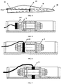
- connection means (3) are integrated in the structurally resistant part corresponding to the beam (4).
- connection means (3) are integrated in the structurally resistant part corresponding to the beam (4).
- Figure 3 shows the successive steps to prepare the connection means.
- First the metal insert (6) is prepared that has an axial drill (7) facing another insert in one of its ends. Later the metal insert (6) is shown joined, by adhesive, to a machined housing in the beam or resistant internal longitudinal structure (8). Finally, two metal inserts (6) are depicted with their axial drills (7) facing to receive pins and nuts (9) that make up the joining points. The aforementioned joint pins (9) work by traction.
- An ultrasound sensor (14) is used in figure 5 ; it sends an impulse that bounces off the end of the pin (9). The sensor measures the time that passes between the emission and reception of the impulse and transforms it into a preload measurement of the bolt that is sent to the control system (12). The ultrasound sensor (14) is at the end of the bolt (9) so that its signal can move lengthwise without any difficulty.
- a load cell (15) is used in figure 6 ; it consists of a metal washer from which its strain is measured. Later, the measurement of the load is transformed to that which the bolt is subject to and the result is sent to the control system (12).
- the location of the sensor (15) is such that it is easy to replace in case of damage.
Landscapes
- Engineering & Computer Science (AREA)
- General Engineering & Computer Science (AREA)
- Mechanical Engineering (AREA)
- Life Sciences & Earth Sciences (AREA)
- Sustainable Development (AREA)
- Sustainable Energy (AREA)
- Chemical & Material Sciences (AREA)
- Combustion & Propulsion (AREA)
- Wind Motors (AREA)
- Force Measurement Appropriate To Specific Purposes (AREA)
- Component Parts Of Construction Machinery (AREA)
- Hydraulic Turbines (AREA)
Claims (5)
- Sensorierte Rotorblattverbindung, deren Verbindung zwischen den Abschnitten des Rotorblatts (1) durch mehrere Verbindungsmittel (3) ausgeführt ist, die im Rotorblatt in dem strukturell widerstandsfähigen, zum Träger (4) gehörigen Teil integriert sind und Metalleinlagen (6) enthalten, die mit Kleber an einem bearbeiteten Gehäuse verbunden sind, das sich an einem Träger des Rotorblatts befindet, wobei die einander gegenüber liegenden Metalleinlagen (6) durch die Stifte und Muttern (9) über die Axialbohrlöcher (7) verbunden sind und die Verbindung der mit einer Verkleidung bedeckten Abschnitte darstellen, und eine Reihe von Sensoren (14, 15) verwendet wird, mit denen die Belastung der Bolzen (9) während der Lebensdauer des Rotorblatts kontrolliert wird, gekennzeichnet dadurch, dass:a. die Sensoren (14, 15) in mindestens einem von mehreren Verbindungsmitteln (3) in einem diagonalen Verbindungsabschnitt sindb. die von den Sensoren gemessenen Signale an ein Steuerungssystem (12) übertragen werden, das sich auf dem Rotorblatt (1) befindet oder nicht und das die auf die Verbindung ausgeübten Kräfte kontrolliertc. die an das Steuerungssystem (12) übertragenen Signale dafür benutzt werden, mögliche Schäden an den Verbindungen festzustellend. die an das Steuerungssystem (12) übertragenen Signale werden benutzt, um die auf die Windenergieanlage übertragenen Lasten zu kontrollierene. die an das Steuerungssystem (12) übertragenen Signale dafür benutzt werden, die Belastungsreichweite zu speichern und Design aufgrund der erhaltenen tatsächlichen Lasten zu verbessern.
- Sensorierte Rotorblattverbindung gemäß Anspruch 1, gekennzeichnet dadurch, dass sich unter den Sensoren mindestens ein Ultraschallsensor am Ende des Verbindungsstifts und ausgerichtet mit dem widerstandsfähigen Material der Einlage befindet.
- Sensorierte Rotorblattverbindung gemäß Anspruch 1, gekennzeichnet dadurch, dass sich unter den Sensoren mindestens eine Lastzelle an einem Teil in der Nähe des Stifts oder zwischen den Wänden der einander gegenüber liegenden Einlagen befindet.
- Sensorierte Rotorblattverbindung gemäß Anspruch 1, gekennzeichnet dadurch, dass sich das Steuerungssystem in der Nabe fern von den durch die Beschleunigung der Rotorblattrotation entstehenden Verzerrungen befindet.
- Sensorierte Rotorblattverbindung gemäß dem vorigen Anspruch, gekennzeichnet dadurch, dass das Steuerungssystem mit den Messungen der Sensoren versorgt wird und deren Signal durch die Innenseite des Trägers, der das Rotorblatt bildet, weiterleitet.
Priority Applications (1)
| Application Number | Priority Date | Filing Date | Title |
|---|---|---|---|
| PL08015978T PL2105609T3 (pl) | 2007-09-14 | 2008-09-10 | Połączenie kołnierzowe dla segmentów łopaty turbiny wiatrowej z tensometrem umieszczonym na śrubach |
Applications Claiming Priority (1)
| Application Number | Priority Date | Filing Date | Title |
|---|---|---|---|
| ES200702442A ES2337645B1 (es) | 2007-09-14 | 2007-09-14 | Union de pala sensorizada. |
Publications (3)
| Publication Number | Publication Date |
|---|---|
| EP2105609A2 EP2105609A2 (de) | 2009-09-30 |
| EP2105609A3 EP2105609A3 (de) | 2015-03-04 |
| EP2105609B1 true EP2105609B1 (de) | 2017-05-03 |
Family
ID=40588239
Family Applications (1)
| Application Number | Title | Priority Date | Filing Date |
|---|---|---|---|
| EP08015978.3A Active EP2105609B1 (de) | 2007-09-14 | 2008-09-10 | Flanschverbindung für Schaufelblattabschnitte einer Windturbine mit Kraftaufnehmer an den Bolzen |
Country Status (5)
| Country | Link |
|---|---|
| US (1) | US20090116962A1 (de) |
| EP (1) | EP2105609B1 (de) |
| CN (1) | CN101457739B (de) |
| ES (2) | ES2337645B1 (de) |
| PL (1) | PL2105609T3 (de) |
Families Citing this family (56)
| Publication number | Priority date | Publication date | Assignee | Title |
|---|---|---|---|---|
| US9765756B2 (en) * | 2008-05-07 | 2017-09-19 | Vestas Wind Systems A/S | Sectional blade |
| US20110158788A1 (en) * | 2008-08-31 | 2011-06-30 | Vestas Wind Systems A/S | A sectional blade |
| FR2948154B1 (fr) * | 2009-07-16 | 2011-09-16 | Astrium Sas | Dispositif d'assemblage de troncons de pales d'eoliennes et procede de liaison de troncons de pales d'eoliennes |
| US20100135796A1 (en) * | 2009-12-01 | 2010-06-03 | Venkateswara Rao Kavala | Monitoring joint efficiency in wind turbine rotor blades |
| US9388789B2 (en) * | 2009-12-02 | 2016-07-12 | Vestas Wind Systems A/S | Sectional wind turbine blade |
| EP2354543B1 (de) * | 2010-01-29 | 2015-10-28 | Siemens Aktiengesellschaft | Verfahren zur Befestigung eines Lastsensors an der Oberfläche eines Rotorblatts und Rotorblatt |
| DE102010040596A1 (de) * | 2010-09-10 | 2012-03-15 | Aloys Wobben | Abnehmbare Rotorblattspitze |
| JP4939640B2 (ja) * | 2010-10-22 | 2012-05-30 | 三菱重工業株式会社 | 風車回転翼 |
| ES2392523B2 (es) | 2011-05-13 | 2013-05-16 | Investigaciones Y Desarrollos Eólicos, S.L. | Sistema de unión de tramos componentes de palas de aerogenerador. |
| CN102269117B (zh) * | 2011-07-05 | 2013-09-18 | 浙江运达风电股份有限公司 | 风电机组桨叶及风电机组 |
| CN102269126B (zh) * | 2011-07-14 | 2013-07-03 | 江苏新誉重工科技有限公司 | 一种电动变桨距控制系统 |
| US8454311B2 (en) * | 2011-09-29 | 2013-06-04 | General Electric Company | Wind turbine blade edge monitoring system |
| US8591187B2 (en) | 2011-12-06 | 2013-11-26 | General Electric Company | System and method for detecting loads transmitted through a blade root of a wind turbine rotor blade |
| US8430632B2 (en) | 2011-12-22 | 2013-04-30 | General Electric Company | System and method for pitching a rotor blade in a wind turbine |
| ES2425026B1 (es) * | 2012-04-03 | 2014-12-05 | Gamesa Innovation & Technology, S.L. | Método de fabricación de un componente de una pala partida de un aerogenerador |
| US20140119914A1 (en) * | 2012-11-01 | 2014-05-01 | General Electric Company | Load control system and method |
| US9297357B2 (en) | 2013-04-04 | 2016-03-29 | General Electric Company | Blade insert for a wind turbine rotor blade |
| US9506452B2 (en) | 2013-08-28 | 2016-11-29 | General Electric Company | Method for installing a shear web insert within a segmented rotor blade assembly |
| US9606234B2 (en) | 2013-10-18 | 2017-03-28 | Tramontane Technologies, Inc. | Amplified optical circuit |
| EP2930350B1 (de) * | 2014-04-11 | 2018-02-14 | Siemens Aktiengesellschaft | Segmentierte Rotorschaufel mit Schraubverbindung |
| DE102014218518A1 (de) * | 2014-09-16 | 2016-03-17 | Dr. Johannes Heidenhain Gmbh | Vorrichtung zur Erfassung von Verformungen eines Rotorblatts und Verfahren zur Montage einer derartigen Vorrichtung |
| CN104747372A (zh) * | 2015-04-20 | 2015-07-01 | 常州易驱动电气科技有限公司 | 一种电动柔性变桨控制系统 |
| DE102016112633A1 (de) * | 2016-07-11 | 2018-01-11 | Wobben Properties Gmbh | Torsionswinkelmessung eines Rotorblatts |
| US10495058B2 (en) | 2017-02-21 | 2019-12-03 | General Electric Company | Joint assembly for rotor blade segments of a wind turbine |
| CN109681391B (zh) * | 2017-10-18 | 2020-09-11 | 中车株洲电力机车研究所有限公司 | 一种叶根螺栓断裂故障检测方法及介质 |
| US10961982B2 (en) | 2017-11-07 | 2021-03-30 | General Electric Company | Method of joining blade sections using thermoplastics |
| DE102017222444A1 (de) * | 2017-12-12 | 2019-06-13 | Robert Bosch Gmbh | Batteriemodul, Verfahren zum Betrieb desselben und dessen Verwendung |
| CN108590984B (zh) * | 2018-04-04 | 2020-05-26 | 浙江运达风电股份有限公司 | 一种风力发电机组叶片载荷监控方法及装置 |
| US11719222B2 (en) | 2018-08-03 | 2023-08-08 | General Electric Company | Method of joining wind turbine rotor blade segments via structural members |
| US10830207B2 (en) | 2018-08-28 | 2020-11-10 | General Electric Company | Spar configuration for jointed wind turbine rotor blades |
| AU2018446413A1 (en) | 2018-10-25 | 2021-05-27 | General Electric Renovables España, S.L. | Spar cap configuration for a jointed wind turbine blade |
| ES2961057T3 (es) | 2018-10-31 | 2024-03-07 | General Electric Renovables Espana Sl | Pala de rotor de turbina eólica unida ("jointed") que tiene combinaciones de materiales distintos a lo largo de su envergadura ("span") para refuerzo con pasadores |
| US11828264B2 (en) | 2018-11-01 | 2023-11-28 | General Electric Company | Compliant structures for jointed rotor blades |
| CN112912618B (zh) | 2018-11-01 | 2024-07-12 | 通用电气可再生能源西班牙有限公司 | 用于连结转子叶片节段的展向延伸销 |
| WO2020091791A1 (en) | 2018-11-01 | 2020-05-07 | General Electric Company | Spacer material for reducing a bond gap between a beam structure and a blade shell of a segmented rotor blade |
| EP3874140A1 (de) | 2018-11-01 | 2021-09-08 | General Electric Company | Stumpfverbindung für eine windturbinenrotorschaufel |
| CN112912614A (zh) | 2018-11-01 | 2021-06-04 | 通用电气公司 | 用于将衬套安装并且固持于转子叶片接头的承载块中的方法 |
| WO2020091784A1 (en) | 2018-11-01 | 2020-05-07 | General Electric Company | Wind turbine jointed rotor blade having a hollow chord-wise extending pin |
| WO2020122864A1 (en) | 2018-12-11 | 2020-06-18 | General Electric Company | Methods for manufacturing blade components for wind turbine rotor blades |
| CN113165288B (zh) | 2018-12-11 | 2023-06-20 | 通用电气公司 | 用于制造用于风力涡轮的转子叶片的叶片节段的结构构件的方法 |
| EP3894194A1 (de) | 2018-12-11 | 2021-10-20 | General Electric Company | Verfahren zur herstellung einer hohlen verbundstruktur, insbesondere eines holmträgers für eine windturbinenlaufschaufel, und zugehöriger dorn |
| JP7234371B2 (ja) | 2018-12-11 | 2023-03-07 | ゼネラル・エレクトリック・カンパニイ | 遷移形状を有するセグメント化されたロータブレード用のビーム構造 |
| CN113165285A (zh) | 2018-12-11 | 2021-07-23 | 通用电气公司 | 用于制造用于风力涡轮的转子叶片的叶片节段的结构构件的方法 |
| WO2020122909A1 (en) | 2018-12-13 | 2020-06-18 | General Electric Company | Jointed rotor blade having a chord-wise extending pin supported via one or more structural members |
| EP3670902A1 (de) * | 2018-12-19 | 2020-06-24 | Siemens Gamesa Renewable Energy A/S | Windturbine mit mindestens einer befestigungsanordnung |
| DK3899246T3 (da) | 2018-12-19 | 2024-05-06 | Lm Wind Power As | Segmenteret rotorvinge med indvendig støttestruktur med varierende fiberorientering til stiftforstærkning |
| EP3899243B1 (de) | 2018-12-20 | 2024-04-10 | LM Wind Power A/S | Rotorblattsegmente, die über innere stützstrukturen miteinander verbunden sind, die einen variablen spalt dazwischen definieren |
| EP3899244B1 (de) | 2018-12-20 | 2025-10-01 | General Electric Renovables España, S.L. | Zusammengefügtes windturbinenrotorblatt mit holmkappe, die aus unterschiedlichen formen von materialien entlang ihrer spannweite konstruiert ist |
| AU2020232943A1 (en) | 2019-03-01 | 2021-09-23 | General Electric Renovables España, S.L. | Jointed wind turbine rotor blade with chord-wise extending pin bushings designed to minimize chord-wise gap |
| US12385465B2 (en) * | 2020-08-28 | 2025-08-12 | Vestas Wind Systems A/S | Connection joint for a split wind turbine blade |
| GB202013647D0 (en) | 2020-08-31 | 2020-10-14 | Lm Wind Power As | Jointed wind turbine blade having improved transitions between varying material combinations |
| GB202020710D0 (en) | 2020-12-30 | 2021-02-10 | Gen Electric | Method of joining segments of a composite component |
| ES2977311T3 (es) * | 2021-01-27 | 2024-08-21 | Nordex Energy Se & Co Kg | Pala de rotor de aerogenerador |
| US12607163B2 (en) | 2022-08-31 | 2026-04-21 | GE Vernova Renovables Espana, S.L.U. | System and method for detecting and responding to rotor blade damage in a wind turbine |
| EP4497582A1 (de) | 2023-07-28 | 2025-01-29 | Siemens Gamesa Renewable Energy A/S | Verfahren zur herstellung einer windturbinenschaufel und windturbinenschaufel |
| EP4497581A1 (de) | 2023-07-28 | 2025-01-29 | Siemens Gamesa Renewable Energy A/S | Verfahren zur herstellung einer windturbinenschaufel und windturbinenschaufel |
Family Cites Families (17)
| Publication number | Priority date | Publication date | Assignee | Title |
|---|---|---|---|---|
| US4292835A (en) * | 1980-02-25 | 1981-10-06 | Raymond Engineering, Inc. | Calibration apparatus and method for strain measuring instruments |
| US4899591A (en) * | 1987-09-11 | 1990-02-13 | Sps Technologies, Inc. | Ultrasonic load indicating member, apparatus and method |
| GB2298624A (en) * | 1995-03-04 | 1996-09-11 | Nigel Howard Mckrill | Light controlled helicopter rotor blade |
| US6354152B1 (en) * | 1996-05-08 | 2002-03-12 | Edward Charles Herlik | Method and system to measure dynamic loads or stresses in aircraft, machines, and structures |
| DK58998A (da) * | 1998-04-30 | 1999-10-31 | Lm Glasfiber As | Vindmølle |
| ES2228121T3 (es) | 1999-11-03 | 2005-04-01 | Vestas Wind Systems A/S | Procedimiento de control de la operacion de una turbina electrica y turbina electrica para usarse en dicho procedimiento. |
| JP2004011616A (ja) * | 2002-06-11 | 2004-01-15 | Shin Meiwa Ind Co Ltd | 風力発電機の風車ブレード構造 |
| US7160083B2 (en) * | 2003-02-03 | 2007-01-09 | General Electric Company | Method and apparatus for wind turbine rotor load control |
| US7004724B2 (en) | 2003-02-03 | 2006-02-28 | General Electric Company | Method and apparatus for wind turbine rotor load control based on shaft radial displacement |
| DK200300670A (da) * | 2003-05-05 | 2004-11-06 | Lm Glasfiber As | Vindmölleving med opdriftsregulerende organer |
| EP1584817A1 (de) * | 2004-04-07 | 2005-10-12 | Gamesa Eolica, S.A. (Sociedad Unipersonal) | Windturbinenblatt |
| US7086834B2 (en) * | 2004-06-10 | 2006-08-08 | General Electric Company | Methods and apparatus for rotor blade ice detection |
| DK176176B1 (da) * | 2004-11-24 | 2006-11-27 | Siemens Wind Power As | Fremgangsmåde og samlestykke til samling af en vinge, fortrinsvis vindmöllevinge, i sektioner |
| ES2265760B1 (es) * | 2005-03-31 | 2008-01-16 | GAMESA INNOVATION & TECHNOLOGY, S.L. | Pala para generadores eolicos. |
| US20070193361A1 (en) * | 2006-02-20 | 2007-08-23 | Davie/Coffee Technologies, LLC | Compressive load sensor by capacitive measurement |
| DE102006036157B4 (de) * | 2006-08-01 | 2016-09-15 | Senvion Gmbh | Kalibrierverfahren |
| EP1911968A1 (de) * | 2006-10-10 | 2008-04-16 | Ecotecnia Energias Renovables S.L. | Regelungssystem für eine Windenergieanlage sowie Verfahren hierzu |
-
2007
- 2007-09-14 ES ES200702442A patent/ES2337645B1/es not_active Expired - Fee Related
-
2008
- 2008-08-28 US US12/199,816 patent/US20090116962A1/en not_active Abandoned
- 2008-09-08 CN CN2008102156184A patent/CN101457739B/zh active Active
- 2008-09-10 ES ES08015978.3T patent/ES2633414T3/es active Active
- 2008-09-10 EP EP08015978.3A patent/EP2105609B1/de active Active
- 2008-09-10 PL PL08015978T patent/PL2105609T3/pl unknown
Also Published As
| Publication number | Publication date |
|---|---|
| ES2337645B1 (es) | 2011-03-11 |
| PL2105609T3 (pl) | 2017-10-31 |
| EP2105609A2 (de) | 2009-09-30 |
| EP2105609A3 (de) | 2015-03-04 |
| CN101457739B (zh) | 2012-12-12 |
| US20090116962A1 (en) | 2009-05-07 |
| ES2337645A1 (es) | 2010-04-27 |
| CN101457739A (zh) | 2009-06-17 |
| ES2633414T3 (es) | 2017-09-21 |
Similar Documents
| Publication | Publication Date | Title |
|---|---|---|
| EP2105609B1 (de) | Flanschverbindung für Schaufelblattabschnitte einer Windturbine mit Kraftaufnehmer an den Bolzen | |
| EP2122430B1 (de) | Verfahren zur zustandsüberwachung eines rotors eines windenergieanlage | |
| US7650786B2 (en) | Apparatus for monitoring the rotational speed in a wind energy plant | |
| US8177505B2 (en) | Method for measuring a rotational position of a rotor blade of a wind turbine and measuring device | |
| EP2350453B1 (de) | Windturbinenschaufel in kombination mit einem lastsensor | |
| DK2354543T3 (en) | Method of attaching a load sensor to a surface of a rotor vane and rotor vane | |
| US8181528B2 (en) | Method and system for ultrasonic inspection of gearbox ring gear | |
| EP2659253B1 (de) | Vorrichtung und verfahren zur bestimmung der last einer windturbinenschaufel | |
| US11448195B2 (en) | Sensor arrangement for a wind turbine | |
| EP2549454A2 (de) | System und Verfahren zum Erkennen von Eis auf einer Laufschaufel einer Windturbine | |
| CN106643906B (zh) | 变桨轴承的监测方法和监测系统 | |
| EP3296564A1 (de) | Antriebsvorrichtung für windturbinen, antriebseinheit für windturbinen und windturbine | |
| US20130280070A1 (en) | Wind turbine blade with cross-sectional sensors | |
| EP2659252B1 (de) | Verfahren und vorrichtung zur bestimmung der last einer windturbinenschaufel | |
| CN102472245B (zh) | 具有用于使负载最小化的装置的风力机 | |
| KR20170042728A (ko) | 구동 시스템에서의 조기 에러 검출 방법, 조기 에러 검출 시스템, 상기 시스템을 포함하는 풍력 발전기 및 상기 시스템의 사용 | |
| JP2019184433A (ja) | 風車ブレードのボルト締結部における締付健全性の計測手法 | |
| EP2110550A1 (de) | Vervielfacher mit sensor | |
| EP2562412B1 (de) | System und Verfahren zur Anpassung des Biegemoments einer Welle in einer Windturbine | |
| EP3514397B1 (de) | Lageranordnung und eine windturbine | |
| EP4390116A1 (de) | System und verfahren zur überwachung der beschädigung eines lagers für eine windturbine | |
| GB2461785A (en) | Mounting assembly for a component of a propeller assembly | |
| EP4715195A1 (de) | Windturbine | |
| Zhang et al. | Non-invasive condition monitoring and diagnostics techniques for wind turbines | |
| CN115824057B (zh) | 一种法兰连接螺栓监测系统及监测方法 |
Legal Events
| Date | Code | Title | Description |
|---|---|---|---|
| PUAI | Public reference made under article 153(3) epc to a published international application that has entered the european phase |
Free format text: ORIGINAL CODE: 0009012 |
|
| AK | Designated contracting states |
Kind code of ref document: A2 Designated state(s): AT BE BG CH CY CZ DE DK EE ES FI FR GB GR HR HU IE IS IT LI LT LU LV MC MT NL NO PL PT RO SE SI SK TR |
|
| AX | Request for extension of the european patent |
Extension state: AL BA MK RS |
|
| RAP1 | Party data changed (applicant data changed or rights of an application transferred) |
Owner name: GAMESA INNOVATION & TECHNOLOGY, S.L. |
|
| PUAL | Search report despatched |
Free format text: ORIGINAL CODE: 0009013 |
|
| AK | Designated contracting states |
Kind code of ref document: A3 Designated state(s): AT BE BG CH CY CZ DE DK EE ES FI FR GB GR HR HU IE IS IT LI LT LU LV MC MT NL NO PL PT RO SE SI SK TR |
|
| AX | Request for extension of the european patent |
Extension state: AL BA MK RS |
|
| RIC1 | Information provided on ipc code assigned before grant |
Ipc: F16L 23/036 20060101ALI20150128BHEP Ipc: F16B 31/02 20060101ALI20150128BHEP Ipc: F03D 11/00 20060101AFI20150128BHEP Ipc: F03D 1/06 20060101ALI20150128BHEP Ipc: F03D 7/00 20060101ALI20150128BHEP |
|
| 17P | Request for examination filed |
Effective date: 20150724 |
|
| RBV | Designated contracting states (corrected) |
Designated state(s): AT BE BG CH CY CZ DE DK EE ES FI FR GB GR HR HU IE IS IT LI LT LU LV MC MT NL NO PL PT RO SE SI SK TR |
|
| RBV | Designated contracting states (corrected) |
Designated state(s): AT BE BG CH CY CZ DE DK EE ES FI FR GB GR HR HU IE IS IT LI LT LU LV MC MT NL NO PL PT RO SE SI SK TR |
|
| RBV | Designated contracting states (corrected) |
Designated state(s): AT BE BG CH CY CZ DE DK EE ES FI FR GB GR HR HU IE IS IT LI LT LU LV MC MT NL NO PL PT RO SE SI SK TR |
|
| AKX | Designation fees paid |
Designated state(s): AT BE BG CH CY CZ DE DK EE ES FI FR GB GR HR HU IE IS IT LI LT LU LV MC MT NL NO PL PT RO SE SI SK TR |
|
| AXX | Extension fees paid |
Extension state: RS Extension state: BA Extension state: AL Extension state: MK |
|
| REG | Reference to a national code |
Ref country code: DE Ref legal event code: R079 Ref document number: 602008050015 Country of ref document: DE Free format text: PREVIOUS MAIN CLASS: F03D0011000000 Ipc: F03D0007020000 |
|
| GRAP | Despatch of communication of intention to grant a patent |
Free format text: ORIGINAL CODE: EPIDOSNIGR1 |
|
| RIC1 | Information provided on ipc code assigned before grant |
Ipc: F16L 23/036 20060101ALI20161129BHEP Ipc: F03D 1/06 20060101ALI20161129BHEP Ipc: F03D 17/00 20160101ALI20161129BHEP Ipc: F03D 7/02 20060101AFI20161129BHEP Ipc: F16B 31/02 20060101ALI20161129BHEP |
|
| INTG | Intention to grant announced |
Effective date: 20161221 |
|
| GRAS | Grant fee paid |
Free format text: ORIGINAL CODE: EPIDOSNIGR3 |
|
| GRAA | (expected) grant |
Free format text: ORIGINAL CODE: 0009210 |
|
| AK | Designated contracting states |
Kind code of ref document: B1 Designated state(s): AT BE BG CH CY CZ DE DK EE ES FI FR GB GR HR HU IE IS IT LI LT LU LV MC MT NL NO PL PT RO SE SI SK TR |
|
| REG | Reference to a national code |
Ref country code: GB Ref legal event code: FG4D |
|
| REG | Reference to a national code |
Ref country code: AT Ref legal event code: REF Ref document number: 890300 Country of ref document: AT Kind code of ref document: T Effective date: 20170515 Ref country code: CH Ref legal event code: EP |
|
| REG | Reference to a national code |
Ref country code: IE Ref legal event code: FG4D |
|
| REG | Reference to a national code |
Ref country code: DE Ref legal event code: R096 Ref document number: 602008050015 Country of ref document: DE |
|
| REG | Reference to a national code |
Ref country code: SE Ref legal event code: TRGR |
|
| REG | Reference to a national code |
Ref country code: FR Ref legal event code: PLFP Year of fee payment: 10 |
|
| REG | Reference to a national code |
Ref country code: NL Ref legal event code: MP Effective date: 20170503 |
|
| REG | Reference to a national code |
Ref country code: AT Ref legal event code: MK05 Ref document number: 890300 Country of ref document: AT Kind code of ref document: T Effective date: 20170503 |
|
| REG | Reference to a national code |
Ref country code: ES Ref legal event code: FG2A Ref document number: 2633414 Country of ref document: ES Kind code of ref document: T3 Effective date: 20170921 |
|
| REG | Reference to a national code |
Ref country code: LT Ref legal event code: MG4D |
|
| PG25 | Lapsed in a contracting state [announced via postgrant information from national office to epo] |
Ref country code: GR Free format text: LAPSE BECAUSE OF FAILURE TO SUBMIT A TRANSLATION OF THE DESCRIPTION OR TO PAY THE FEE WITHIN THE PRESCRIBED TIME-LIMIT Effective date: 20170804 Ref country code: HR Free format text: LAPSE BECAUSE OF FAILURE TO SUBMIT A TRANSLATION OF THE DESCRIPTION OR TO PAY THE FEE WITHIN THE PRESCRIBED TIME-LIMIT Effective date: 20170503 Ref country code: AT Free format text: LAPSE BECAUSE OF FAILURE TO SUBMIT A TRANSLATION OF THE DESCRIPTION OR TO PAY THE FEE WITHIN THE PRESCRIBED TIME-LIMIT Effective date: 20170503 Ref country code: NO Free format text: LAPSE BECAUSE OF FAILURE TO SUBMIT A TRANSLATION OF THE DESCRIPTION OR TO PAY THE FEE WITHIN THE PRESCRIBED TIME-LIMIT Effective date: 20170803 Ref country code: LT Free format text: LAPSE BECAUSE OF FAILURE TO SUBMIT A TRANSLATION OF THE DESCRIPTION OR TO PAY THE FEE WITHIN THE PRESCRIBED TIME-LIMIT Effective date: 20170503 |
|
| PG25 | Lapsed in a contracting state [announced via postgrant information from national office to epo] |
Ref country code: BG Free format text: LAPSE BECAUSE OF FAILURE TO SUBMIT A TRANSLATION OF THE DESCRIPTION OR TO PAY THE FEE WITHIN THE PRESCRIBED TIME-LIMIT Effective date: 20170803 Ref country code: IS Free format text: LAPSE BECAUSE OF FAILURE TO SUBMIT A TRANSLATION OF THE DESCRIPTION OR TO PAY THE FEE WITHIN THE PRESCRIBED TIME-LIMIT Effective date: 20170903 Ref country code: NL Free format text: LAPSE BECAUSE OF FAILURE TO SUBMIT A TRANSLATION OF THE DESCRIPTION OR TO PAY THE FEE WITHIN THE PRESCRIBED TIME-LIMIT Effective date: 20170503 Ref country code: LV Free format text: LAPSE BECAUSE OF FAILURE TO SUBMIT A TRANSLATION OF THE DESCRIPTION OR TO PAY THE FEE WITHIN THE PRESCRIBED TIME-LIMIT Effective date: 20170503 |
|
| PG25 | Lapsed in a contracting state [announced via postgrant information from national office to epo] |
Ref country code: CZ Free format text: LAPSE BECAUSE OF FAILURE TO SUBMIT A TRANSLATION OF THE DESCRIPTION OR TO PAY THE FEE WITHIN THE PRESCRIBED TIME-LIMIT Effective date: 20170503 Ref country code: RO Free format text: LAPSE BECAUSE OF FAILURE TO SUBMIT A TRANSLATION OF THE DESCRIPTION OR TO PAY THE FEE WITHIN THE PRESCRIBED TIME-LIMIT Effective date: 20170503 Ref country code: SK Free format text: LAPSE BECAUSE OF FAILURE TO SUBMIT A TRANSLATION OF THE DESCRIPTION OR TO PAY THE FEE WITHIN THE PRESCRIBED TIME-LIMIT Effective date: 20170503 Ref country code: EE Free format text: LAPSE BECAUSE OF FAILURE TO SUBMIT A TRANSLATION OF THE DESCRIPTION OR TO PAY THE FEE WITHIN THE PRESCRIBED TIME-LIMIT Effective date: 20170503 Ref country code: DK Free format text: LAPSE BECAUSE OF FAILURE TO SUBMIT A TRANSLATION OF THE DESCRIPTION OR TO PAY THE FEE WITHIN THE PRESCRIBED TIME-LIMIT Effective date: 20170503 |
|
| REG | Reference to a national code |
Ref country code: DE Ref legal event code: R097 Ref document number: 602008050015 Country of ref document: DE |
|
| PLBE | No opposition filed within time limit |
Free format text: ORIGINAL CODE: 0009261 |
|
| STAA | Information on the status of an ep patent application or granted ep patent |
Free format text: STATUS: NO OPPOSITION FILED WITHIN TIME LIMIT |
|
| 26N | No opposition filed |
Effective date: 20180206 |
|
| REG | Reference to a national code |
Ref country code: CH Ref legal event code: PL |
|
| PG25 | Lapsed in a contracting state [announced via postgrant information from national office to epo] |
Ref country code: SI Free format text: LAPSE BECAUSE OF FAILURE TO SUBMIT A TRANSLATION OF THE DESCRIPTION OR TO PAY THE FEE WITHIN THE PRESCRIBED TIME-LIMIT Effective date: 20170503 Ref country code: MC Free format text: LAPSE BECAUSE OF FAILURE TO SUBMIT A TRANSLATION OF THE DESCRIPTION OR TO PAY THE FEE WITHIN THE PRESCRIBED TIME-LIMIT Effective date: 20170503 |
|
| REG | Reference to a national code |
Ref country code: IE Ref legal event code: MM4A |
|
| REG | Reference to a national code |
Ref country code: BE Ref legal event code: MM Effective date: 20170930 |
|
| PG25 | Lapsed in a contracting state [announced via postgrant information from national office to epo] |
Ref country code: LU Free format text: LAPSE BECAUSE OF NON-PAYMENT OF DUE FEES Effective date: 20170910 |
|
| PG25 | Lapsed in a contracting state [announced via postgrant information from national office to epo] |
Ref country code: IE Free format text: LAPSE BECAUSE OF NON-PAYMENT OF DUE FEES Effective date: 20170910 Ref country code: LI Free format text: LAPSE BECAUSE OF NON-PAYMENT OF DUE FEES Effective date: 20170930 Ref country code: CH Free format text: LAPSE BECAUSE OF NON-PAYMENT OF DUE FEES Effective date: 20170930 |
|
| PG25 | Lapsed in a contracting state [announced via postgrant information from national office to epo] |
Ref country code: BE Free format text: LAPSE BECAUSE OF NON-PAYMENT OF DUE FEES Effective date: 20170930 |
|
| REG | Reference to a national code |
Ref country code: FR Ref legal event code: PLFP Year of fee payment: 11 |
|
| PG25 | Lapsed in a contracting state [announced via postgrant information from national office to epo] |
Ref country code: MT Free format text: LAPSE BECAUSE OF NON-PAYMENT OF DUE FEES Effective date: 20170910 |
|
| PG25 | Lapsed in a contracting state [announced via postgrant information from national office to epo] |
Ref country code: HU Free format text: LAPSE BECAUSE OF FAILURE TO SUBMIT A TRANSLATION OF THE DESCRIPTION OR TO PAY THE FEE WITHIN THE PRESCRIBED TIME-LIMIT; INVALID AB INITIO Effective date: 20080910 |
|
| PG25 | Lapsed in a contracting state [announced via postgrant information from national office to epo] |
Ref country code: CY Free format text: LAPSE BECAUSE OF NON-PAYMENT OF DUE FEES Effective date: 20170503 |
|
| PG25 | Lapsed in a contracting state [announced via postgrant information from national office to epo] |
Ref country code: TR Free format text: LAPSE BECAUSE OF FAILURE TO SUBMIT A TRANSLATION OF THE DESCRIPTION OR TO PAY THE FEE WITHIN THE PRESCRIBED TIME-LIMIT Effective date: 20170503 |
|
| PG25 | Lapsed in a contracting state [announced via postgrant information from national office to epo] |
Ref country code: PT Free format text: LAPSE BECAUSE OF FAILURE TO SUBMIT A TRANSLATION OF THE DESCRIPTION OR TO PAY THE FEE WITHIN THE PRESCRIBED TIME-LIMIT Effective date: 20170503 |
|
| REG | Reference to a national code |
Ref country code: DE Ref legal event code: R082 Ref document number: 602008050015 Country of ref document: DE Ref country code: DE Ref legal event code: R081 Ref document number: 602008050015 Country of ref document: DE Owner name: SIEMENS GAMESA RENEWABLE ENERGY INNOVATION & T, ES Free format text: FORMER OWNER: GAMESA INNOVATION & TECHNOLOGY, S.L., SARRIGUREN, ES |
|
| PGFP | Annual fee paid to national office [announced via postgrant information from national office to epo] |
Ref country code: IT Payment date: 20210920 Year of fee payment: 14 |
|
| PGFP | Annual fee paid to national office [announced via postgrant information from national office to epo] |
Ref country code: SE Payment date: 20210907 Year of fee payment: 14 |
|
| REG | Reference to a national code |
Ref country code: SE Ref legal event code: EUG |
|
| PG25 | Lapsed in a contracting state [announced via postgrant information from national office to epo] |
Ref country code: SE Free format text: LAPSE BECAUSE OF NON-PAYMENT OF DUE FEES Effective date: 20220911 |
|
| PG25 | Lapsed in a contracting state [announced via postgrant information from national office to epo] |
Ref country code: IT Free format text: LAPSE BECAUSE OF NON-PAYMENT OF DUE FEES Effective date: 20220910 |
|
| PGFP | Annual fee paid to national office [announced via postgrant information from national office to epo] |
Ref country code: DE Payment date: 20240926 Year of fee payment: 17 Ref country code: FI Payment date: 20240926 Year of fee payment: 17 |
|
| PGFP | Annual fee paid to national office [announced via postgrant information from national office to epo] |
Ref country code: GB Payment date: 20240924 Year of fee payment: 17 |
|
| PGFP | Annual fee paid to national office [announced via postgrant information from national office to epo] |
Ref country code: FR Payment date: 20240925 Year of fee payment: 17 |
|
| PGFP | Annual fee paid to national office [announced via postgrant information from national office to epo] |
Ref country code: PL Payment date: 20240819 Year of fee payment: 17 |
|
| PGFP | Annual fee paid to national office [announced via postgrant information from national office to epo] |
Ref country code: ES Payment date: 20241021 Year of fee payment: 17 |
|
| PG25 | Lapsed in a contracting state [announced via postgrant information from national office to epo] |
Ref country code: FI Free format text: LAPSE BECAUSE OF NON-PAYMENT OF DUE FEES Effective date: 20250910 |