EP2105649B1 - Cadre de machine - Google Patents
Cadre de machine Download PDFInfo
- Publication number
- EP2105649B1 EP2105649B1 EP20080153496 EP08153496A EP2105649B1 EP 2105649 B1 EP2105649 B1 EP 2105649B1 EP 20080153496 EP20080153496 EP 20080153496 EP 08153496 A EP08153496 A EP 08153496A EP 2105649 B1 EP2105649 B1 EP 2105649B1
- Authority
- EP
- European Patent Office
- Prior art keywords
- machine frame
- load beam
- initial machine
- beam device
- frame
- Prior art date
- Legal status (The legal status is an assumption and is not a legal conclusion. Google has not performed a legal analysis and makes no representation as to the accuracy of the status listed.)
- Not-in-force
Links
Images




Classifications
-
- F—MECHANICAL ENGINEERING; LIGHTING; HEATING; WEAPONS; BLASTING
- F16—ENGINEERING ELEMENTS AND UNITS; GENERAL MEASURES FOR PRODUCING AND MAINTAINING EFFECTIVE FUNCTIONING OF MACHINES OR INSTALLATIONS; THERMAL INSULATION IN GENERAL
- F16M—FRAMES, CASINGS OR BEDS OF ENGINES, MACHINES OR APPARATUS, NOT SPECIFIC TO ENGINES, MACHINES OR APPARATUS PROVIDED FOR ELSEWHERE; STANDS; SUPPORTS
- F16M1/00—Frames or casings of engines, machines or apparatus; Frames serving as machinery beds
Definitions
- the invention relates to a machine frame for receiving machines or systems according to the preamble of claim 1.
- Air compressor systems are used to detect oil and gas deposits and for this purpose must be adapted to suitable means of transport such as e.g. Lorries or reconnaissance vessels are loaded.
- the system is for this purpose e.g. captured by container cranes on the machine frame and can be easily loaded and stowed on the transport vehicles.
- the CH 692 738 A5 describes a container with a platform and a frame structure.
- This container is designed so that it can be loaded and unloaded by a transport vehicle itself, or alternatively can be handled with a forklift.
- the container has a platform with two Longitudinal bars, which are structurally designed so that they serve as rails to raise the container via two rollers on a transport vehicle can and are additionally provided with forklift pockets to handle the container alternatively with a forklift can.
- an H-shaped elevator frame of two side rails and a cross member can be attached.
- This container has the disadvantage that the elevator frame must be stored separately when not in use and thus requires additional storage space. Since the cross member of this elevator frame is disposed between the upper cross member and the lower cross member, it is not suitable as a load beam device due to its low installation, in order to perform maintenance, repair and maintenance of the arranged within the machine frame machinery or equipment in a simple manner.
- the GB 1 247 349 describes a container device, which consists of a stable force-absorbing frame and the actual box-shaped container, which only needs to be stable so that he can carry the contents.
- the DE-OS 21 65 203 describes a box frame for device construction, especially for air conditioning or supply and exhaust devices. This depends on the design of the corner connectors, with which the profile strips of the frame can be easily and quickly assembled to form a stable frame skeleton. On the support piece of the corner connector eyebolts for hanging the box frame can be screwed via ropes.
- the DE-OS 23 00 895 describes an arrangement with a self-supporting frame construction for a mobile heat station.
- the DE 199 53 900 A1 discloses a vehicle having suction dredger assemblies mounted on a support.
- At the load bar means, e.g. a hoist with which e.g. the machine or plant component to be serviced or repaired can be lifted and moved.
- the load beam device is only attached to the upper horizontal strut when needed.
- the load beam device can be removed again, so that it does not hinder the implementation of the plant or its transport.
- the load beam device has at least one load beam component arranged on the machine frame and / or at least one element of the frame.
- To install the load beam device only components are used, which are already present on the machine frame. These are components of the frame, which are assembled in a different configuration to a load beam device, or a load beam device which is already present and only needs to be brought into a working position. It can be provided as a further alternative, a load beam component on the machine frame, which is in a rest position and, if necessary in a working position is movable and is completed there by means of a frame member to a load beam device. It is not necessary to resort to additional components which are either difficult to obtain or may have only limited suitability.
- the installation can be done either by hand or with the help of simple, usually existing tools, such as wrenches, etc.
- the load beam device can therefore locally, z. B. in structurally weak, inaccessible or inhospitable regions, as z. B. in the search for natural resources is the case, installed and used there with the usual means there.
- the load beam device preferably has two supports and a bar connecting the two supports. There are only three simple components required for this embodiment, which can be provided from located on the machine frame components.
- At least one upper horizontal strut has at least one releasably secured frame element. From one or more of the upper horizontal struts frame elements can be removed, whereby the affected strut is interrupted. Although the machine frame is weakened at the points in question, this is justifiable to the extent that it can be justified in terms of maintenance and repair Repair work the system is not in operation anyway and thus the machine frame is not charged in the usual way.
- the releasably secured frame members are preferably provided on or in the upper horizontal bar, because it is easily accessible. Moreover, it is advantageous if, at the location where the load beam device is installed, a free space is created under the load beam device in order to carry out the necessary work, in particular if lifting devices are to be mounted on the load beam device. By expanding the frame element of the necessary work space is created.
- the releasably secured frame members are provided in the areas where the machines or system components requiring repair or maintenance are arranged within the frame.
- the length of the releasably secured frame members is tuned to the desired dimensions of the load beam device. It can be provided in the frame different lengths frame members to assemble different high load beam devices can. In order to provide several frame members of different lengths, they can also be provided elsewhere than in the upper horizontal struts. Removable fastened frame members may preferably also be components of other struts, in particular of connecting struts, which may be formed as horizontal or vertical struts.
- the frame elements After carrying out the maintenance, service and repair work, the frame elements are returned to their original position original location used in the struts, so that the rigidity of the frame is restored.
- Vorrugitate the load beam device or the load beam component is arranged on a strut from a rest to a working position and vice versa foldable or pivotable.
- the load beam device or the load beam component is pivoted away when not in use in its rest position or folded away and remains on the machine frame.
- the pivoting away or folding away in the rest position takes place in a plane parallel to a wall surface of the frame.
- the load beam component preferably has at least one support.
- the load beam component may, for example, also have both supports or a support and the associated beam.
- the load beam component is preferably connectable to at least one releasably secured frame member.
- the load beam device preferably consists entirely of detachably fastened frame elements.
- the frame members are screwed together and / or pluggable with each other or with the Lastbalkenkomponente. In this way, the assembly and disassembly of the load beam device is facilitated, which is feasible without much tooling.
- the frame element and / or the load beam component preferably has a mounting plate at the end.
- Such Mounting plate is provided so that the components to be joined together, for example, can be screwed.
- the machine frame has the dimensions of a container. This makes it possible to easily transport the system with the machine frame on a truck or a train carriage. It also simplifies transport on a container ship.
- the beam may include means for attaching hoists such as e.g. a pulley, a cable, a chain hoist or the like. Such means are e.g. Holes in the beam into which the hoist in question can be hung.
- hoists such as e.g. a pulley, a cable, a chain hoist or the like.
- the machine frame is preferably designed for receiving an air compressor system which has a piston compressor.
- the load beam device is preferably attachable in the region of the piston compressor in this embodiment. This makes it possible to easily replace, for example, the piston rings of the reciprocating compressor.
- the machine frame is preferably used everywhere where large machines or facilities are provided, the machinery or equipment or its components can not be moved by hand due to their weight.
- the overall height of the machine frame is preferably> 1.50 m, in particular> 2.0 m.
- the weight of the machines, systems and their components is usually more than 100 kg, in particular more than 500 kg and can also be up to several thousand kg.
- the advantage of the machine frame according to the invention with load beam device is that it fulfills the task of picking up static and dynamic loads at times when the plant or machine is being used as intended and at the same time during maintenance, service and repair operations of the plant or machine can be used to perform just this work at any time, in any place and independently of additional scaffolding.
- FIG. 1 an air compressor system 1 is shown, which has substantially three sections, which are formed by a reciprocating compressor 2, a drive motor 3 and a screw compressor 4 including the associated additional components.
- the air compressor installation 1 is surrounded by a machine frame 10 in the form of a frame, with individual components of the air compressor installation 1 being fastened to or on the machine frame 10.
- the machine frame 10 has lower horizontal struts 14a-d, upper horizontal struts 12a-d, and vertical struts 16a-d at the four corners. Further, horizontal connecting webs 18a, b are provided between the upper horizontal struts 12a and 12c. In the area between the vertical struts 16a and 16b there are further vertical struts as connecting struts 20a, b, c, which are in turn connected to each other via horizontal connecting struts 18c and thus effect an additional stiffening of the overall frame.
- the upper horizontal struts 12a-d have releasably secured frame members 22a-d.
- FIG. 2 is the in Fig. 1 shown machine frame 10 shown simplified. It can be seen that the upper horizontal struts 12a, 12b and 12c each have releasably secured frame members 22a, b and c. These frame members 22a, b and c are suitably connected to the horizontal struts, eg plugged or screwed and are thus part of the struts.
- Fig. 3 is the in Fig. 2 shown frames, wherein from the three frame members 22a, b and c, a load beam device 30 is assembled.
- the load beam device 30 is located on the horizontal strut 12b, wherein the frame member 22b for Structure of the load beam device 30 has been used and forms the beam 32.
- the two supports 34a, b of the load beam device 30 are formed by the dismounted frame elements 22a and 22c.
- the frame members 22a, c define the height of the load beam means.
- the load beam device 30 can be dismantled again by the respective frame elements 22a, b and c are used in their original location in the horizontal struts 12a, b and c.
- FIG. 4a an exemplary embodiment of a load beam device 30 is shown. It can be seen that the three frame elements 22a, b and c forming the load beam device 30, which form the supports 34a, b and the beam 32, are screwed together. For this purpose, for example, the frame member 22b on a mounting plate 40, which allows a screw with the adjacent elements.
- the load beam device 30 is also formed by the frame members 22a, b and c, wherein, in contrast to the Fig. 4a the individual frame elements are connected to each other by plugging.
- each mandrel 43 is provided in the respective frame elements or struts 12a, b.
- the load beam device 30 is completely present and arranged on the frame.
- the load beam device consists of the struts 34 a, b and the beam 32.
- the load beam device 30 is located in the plane of the top surface of the machine frame 10 and can as in the right part of Fig. 6a can be seen, are erected from this lying rest position in the working position. This is done by folding around the axis 39.
- the frame element 22b is removed from the strut 12b to create the free space 24b. This frame element 22b is not used in the construction of the load beam device 30.
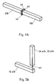
- FIG. 6b the connecting elements or the folding mechanism are shown enlarged. It can be seen that a multi-part hinge 51 partly with the support 34a, b and partly with the Strut 12a, b is connected. The individual hinge parts are connected by a hinge pin 52.
- a load beam component 36, support 34b and beam 32 is provided in the Fig. 7a .
- the load beam component 36 is pivotally mounted and is in the left-hand illustration in the lowered rest position, in which the load beam component 36 is arranged parallel to a wall surface of the machine frame 10.
- a pivoting mechanism is shown, which allows the load beam component 36 about the axis 39 to pivot upward into the working position (see right-hand illustration of Fig. 7a ). Also in this embodiment, the frame member 22b is removed from the strut 12b to provide the necessary working space 24b. After erecting the load beam component 36, the frame member 22b is attached as a post 34a to the load beam component 36 and connected to the horizontal strut 12b and secured.
- Fig. 7b The details of the pivoting means and the connection of the strut 34a is in the Fig. 7b shown. It can be seen that the multi-part hinge 51 is connected in part to the support 34a, b and partly to the strut 12a, b. The individual hinge parts are also connected by the hinge pin 52.
Landscapes
- Engineering & Computer Science (AREA)
- General Engineering & Computer Science (AREA)
- Mechanical Engineering (AREA)
- Load-Engaging Elements For Cranes (AREA)
Claims (14)
- Cadre évolutif (10) pour machines, conçu pour recevoir des machines ou des installations et muni d'un bâti tridimensionnel d'encadrement comprenant des montants verticaux (16a-d), et des entretoises horizontales inférieures et supérieures (12a-d, 14a-d), ledit cadre évolutif pour machines pouvant être transformé en un cadre pour machines équipé d'un dispositif à poutre de charge,
sachant que seuls sont utilisés des éléments constitutifs déjà présents sur ledit cadre évolutif pour machines, caractérisé par le fait que le cadre évolutif pour machines comporte au moins une entretoise horizontale supérieure pourvue d'au moins un élément d'encadrement fixé de manière amovible et faisant partie de ladite entretoise horizontale, permettant ainsi de former dans ledit cadre pour machines, après dépose, une entretoise horizontale offrant un espace vacant. - Cadre évolutif pour machines, selon la revendication 1, caractérisé par le fait que le dispositif (30) à poutre de charge peut être installé sur une entretoise horizontale supérieure (12a-d).
- Cadre évolutif pour machines, selon la revendication 1 ou 2, caractérisé par le fait que le dispositif (30) à poutre de charge présente au moins un composant (36) de poutre de charge, situé sur ledit cadre évolutif (10) pour machines, et/ou au moins un élément (22a-d) dudit cadre évolutif (10) pour machines.
- Cadre évolutif pour machines, selon l'une des revendications 1 à 3, caractérisé par le fait que le dispositif (30) à poutre de charge comprend deux jambages d'appui (34a, b), et une poutre (32) reliant les deux jambages d'appui (34a, b).
- Cadre évolutif pour machines, selon l'une des revendications 1 à 4, caractérisé par le fait que le dispositif (30) à poutre de charge est installé dans la région de l'élément d'encadrement (22a-d) fixé de manière libérable.
- Cadre évolutif pour machines, selon l'une des revendications 1 à 5, caractérisé par le fait que le dispositif (30) à poutre de charge, ou le composant (36) de poutre de charge, est monté sur une entretoise (12a-d, 14a-d, 16a-d) avec faculté de rabat ou de pivotement d'une position de repos à une position de travail, et inversement.
- Cadre évolutif pour machines, selon l'une des revendications 3 à 6, caractérisé par le fait que le composant (36) de poutre de charge présente au moins un jambage d'appui (34a, b).
- Cadre évolutif pour machines, selon l'une des revendications 3 à 7, caractérisé par le fait que le composant (36) de poutre de charge peut être relié à au moins un élément d'encadrement (22a-d) fixé de manière libérable.
- Cadre évolutif pour machines, selon l'une des revendications 1 à 8, caractérisé par le fait que le dispositif (30) à poutre de charge est constitué d'éléments d'encadrement (22a-d) fixés de manière libérable.
- Cadre évolutif pour machines, selon l'une des revendications 3 à 9, caractérisé par le fait que les éléments d'encadrement (22a-d) sont reliés les uns aux autres, ou au composant (36) de poutre de charge, avec faculté de vissage et/ou d'emboîtement.
- Cadre évolutif pour machines, selon l'une des revendications 3 à 10, caractérisé par le fait que l'élément d'encadrement (22a-d), et/ou le composant (36, 38) de poutre de charge, comporte(nt) une plaquette de montage (40) aux extrémités.
- Cadre évolutif pour machines, selon l'une des revendications 1 à 11, caractérisé par le fait que la poutre (32) présente des moyens de fixation d'un appareillage élévateur.
- Cadre évolutif pour machines, selon l'une des revendications 1 à 12, caractérisé par le fait qu'il est réalisé en vue de recevoir une installation (1) à compresseur d'air, équipée d'un compresseur (2) à pistons.
- Cadre évolutif pour machines, selon la revendication 13, caractérisé par le fait que le dispositif (30) à poutre de charge peut être installé dans la région du compresseur (2) à pistons.
Priority Applications (1)
| Application Number | Priority Date | Filing Date | Title |
|---|---|---|---|
| EP20080153496 EP2105649B1 (fr) | 2008-03-28 | 2008-03-28 | Cadre de machine |
Applications Claiming Priority (1)
| Application Number | Priority Date | Filing Date | Title |
|---|---|---|---|
| EP20080153496 EP2105649B1 (fr) | 2008-03-28 | 2008-03-28 | Cadre de machine |
Publications (2)
| Publication Number | Publication Date |
|---|---|
| EP2105649A1 EP2105649A1 (fr) | 2009-09-30 |
| EP2105649B1 true EP2105649B1 (fr) | 2013-01-30 |
Family
ID=39684438
Family Applications (1)
| Application Number | Title | Priority Date | Filing Date |
|---|---|---|---|
| EP20080153496 Not-in-force EP2105649B1 (fr) | 2008-03-28 | 2008-03-28 | Cadre de machine |
Country Status (1)
| Country | Link |
|---|---|
| EP (1) | EP2105649B1 (fr) |
Families Citing this family (2)
| Publication number | Priority date | Publication date | Assignee | Title |
|---|---|---|---|---|
| DE102014106333B4 (de) * | 2014-05-07 | 2023-02-16 | Pester Pac Automation Gmbh | Vorrichtung |
| EP4357660A1 (fr) * | 2022-10-21 | 2024-04-24 | SOMIC Verpackungsmaschinen GmbH & Co. KG | Châssis de machine et ensemble de fixation constitué d'un châssis de machine et d'au moins un élément de fixation |
Family Cites Families (8)
| Publication number | Priority date | Publication date | Assignee | Title |
|---|---|---|---|---|
| GB1247349A (en) * | 1968-06-17 | 1971-09-22 | Norman Thomas Tamplin | Bulk container unit |
| DE2165203A1 (de) * | 1971-12-29 | 1973-07-05 | Smitka Guenter | Kastenrahmen fuer den geraetebau, insbesondere klima- bzw. zu- und abluftgeraete |
| BE793670A (fr) * | 1972-02-01 | 1973-05-02 | Magyar Hajo Es Darugyar | Construction de chassis autoportante et agencement pour une centrale thermique mobile, pouvant etre deplacee a l'etat monte |
| DE4333048C2 (de) * | 1993-09-29 | 1997-01-30 | Abb Patent Gmbh | Gestell zur Aufnahme von Maschinen und Geräten |
| CH692738A5 (de) * | 1997-10-17 | 2002-10-15 | Ruag Land Systems | Container. |
| DE19953900A1 (de) * | 1999-11-10 | 2001-05-17 | Sabatec Saugbaggertechnologie | Saugbaggermodul |
| DE10261274B4 (de) * | 2002-12-27 | 2005-04-21 | Eisenmann Maschinenbau Gmbh & Co. Kg | Rahmenteil für den Grundrahmen einer industriellen Anlage |
| AT9916U1 (de) * | 2006-08-16 | 2008-05-15 | Leobersdorfer Maschf | Mehrstufiger verdichter |
-
2008
- 2008-03-28 EP EP20080153496 patent/EP2105649B1/fr not_active Not-in-force
Also Published As
| Publication number | Publication date |
|---|---|
| EP2105649A1 (fr) | 2009-09-30 |
Similar Documents
| Publication | Publication Date | Title |
|---|---|---|
| DE69619695T2 (de) | Jettriebwerkstransportvorrichtung | |
| EP1348667A2 (fr) | Dispositif de levage pour véhicules, unités de montages, machines ou similaires | |
| WO2011076238A1 (fr) | Pieds de transport réglables | |
| DE3704598A1 (de) | Bewegliches geruest | |
| EP2531437B1 (fr) | Procédé de fabrication d'un rail de roulement et rail de roulement pour un dispositif de levage à rail de roulement | |
| DE3420737A1 (de) | Zusatzeinrichtung fuer hoehenverstellbare arbeitsgerueste | |
| EP3016843A1 (fr) | Convoyeur aérien équipé de modules de châssis porteur | |
| DE1584525B1 (de) | Batterieschalung | |
| EP0464062B1 (fr) | Dispositif d'inspection du cote inferieur de ponts | |
| DE102015107985A1 (de) | Vorrichtung zum Transportieren von Gasen | |
| EP2105649A1 (fr) | Cadre de machine | |
| DE102012209988A1 (de) | Unterbaumodul für eine mobile Landbohranlage und Verfahren zum Auf- und Abbau solcher Unterbaumodule | |
| DE4034053C2 (fr) | ||
| DE3411299C2 (fr) | ||
| DE102008029872B4 (de) | Mobiles Gebäude | |
| DE20321855U1 (de) | Stahlturm für eine Windkraftanlage | |
| DE3305323A1 (de) | Schiff mit einem auf dem innenboden angeordneten rohrleitungssystem | |
| EP2472071B1 (fr) | Installation industrielle dotée d'un capot insonorisant | |
| EP3663574B1 (fr) | Dispositif de transport pour un moyeu de rotor d'une éolienne | |
| WO2009095114A1 (fr) | Palonnier télescopique | |
| DE202009019097U1 (de) | Modularer Transportbehälter | |
| DE3723452A1 (de) | Schiebeverdeckgestell fuer lastfahrzeuge | |
| EP3947838A1 (fr) | Système de cadre modulaire pour combinaisons empilables dans le domaine de la construction d'installations industrielles | |
| DE19731445A1 (de) | Transport- und Lagerbehälter | |
| EP4448437B1 (fr) | Mât pour une grue empileuse |
Legal Events
| Date | Code | Title | Description |
|---|---|---|---|
| PUAI | Public reference made under article 153(3) epc to a published international application that has entered the european phase |
Free format text: ORIGINAL CODE: 0009012 |
|
| 17P | Request for examination filed |
Effective date: 20090213 |
|
| AK | Designated contracting states |
Kind code of ref document: A1 Designated state(s): AT BE BG CH CY CZ DE DK EE ES FI FR GB GR HR HU IE IS IT LI LT LU LV MC MT NL NO PL PT RO SE SI SK TR |
|
| AX | Request for extension of the european patent |
Extension state: AL BA MK RS |
|
| AKX | Designation fees paid |
Designated state(s): AT BE BG CH CY CZ DE DK EE ES FI FR GB GR HR HU IE IS IT LI LT LU LV MC MT NL NO PL PT RO SE SI SK TR |
|
| 17Q | First examination report despatched |
Effective date: 20100729 |
|
| GRAP | Despatch of communication of intention to grant a patent |
Free format text: ORIGINAL CODE: EPIDOSNIGR1 |
|
| GRAS | Grant fee paid |
Free format text: ORIGINAL CODE: EPIDOSNIGR3 |
|
| GRAP | Despatch of communication of intention to grant a patent |
Free format text: ORIGINAL CODE: EPIDOSNIGR1 |
|
| GRAA | (expected) grant |
Free format text: ORIGINAL CODE: 0009210 |
|
| AK | Designated contracting states |
Kind code of ref document: B1 Designated state(s): AT BE BG CH CY CZ DE DK EE ES FI FR GB GR HR HU IE IS IT LI LT LU LV MC MT NL NO PL PT RO SE SI SK TR |
|
| REG | Reference to a national code |
Ref country code: GB Ref legal event code: FG4D Free format text: NOT ENGLISH |
|
| REG | Reference to a national code |
Ref country code: CH Ref legal event code: EP |
|
| REG | Reference to a national code |
Ref country code: AT Ref legal event code: REF Ref document number: 595776 Country of ref document: AT Kind code of ref document: T Effective date: 20130215 Ref country code: CH Ref legal event code: EP |
|
| REG | Reference to a national code |
Ref country code: IE Ref legal event code: FG4D Free format text: LANGUAGE OF EP DOCUMENT: GERMAN |
|
| REG | Reference to a national code |
Ref country code: DE Ref legal event code: R096 Ref document number: 502008009189 Country of ref document: DE Effective date: 20130328 |
|
| REG | Reference to a national code |
Ref country code: NO Ref legal event code: T2 Effective date: 20130130 |
|
| REG | Reference to a national code |
Ref country code: LT Ref legal event code: MG4D |
|
| REG | Reference to a national code |
Ref country code: NL Ref legal event code: VDEP Effective date: 20130130 |
|
| PG25 | Lapsed in a contracting state [announced via postgrant information from national office to epo] |
Ref country code: LT Free format text: LAPSE BECAUSE OF FAILURE TO SUBMIT A TRANSLATION OF THE DESCRIPTION OR TO PAY THE FEE WITHIN THE PRESCRIBED TIME-LIMIT Effective date: 20130130 Ref country code: ES Free format text: LAPSE BECAUSE OF FAILURE TO SUBMIT A TRANSLATION OF THE DESCRIPTION OR TO PAY THE FEE WITHIN THE PRESCRIBED TIME-LIMIT Effective date: 20130511 Ref country code: IS Free format text: LAPSE BECAUSE OF FAILURE TO SUBMIT A TRANSLATION OF THE DESCRIPTION OR TO PAY THE FEE WITHIN THE PRESCRIBED TIME-LIMIT Effective date: 20130530 Ref country code: SE Free format text: LAPSE BECAUSE OF FAILURE TO SUBMIT A TRANSLATION OF THE DESCRIPTION OR TO PAY THE FEE WITHIN THE PRESCRIBED TIME-LIMIT Effective date: 20130130 Ref country code: BG Free format text: LAPSE BECAUSE OF FAILURE TO SUBMIT A TRANSLATION OF THE DESCRIPTION OR TO PAY THE FEE WITHIN THE PRESCRIBED TIME-LIMIT Effective date: 20130430 |
|
| PG25 | Lapsed in a contracting state [announced via postgrant information from national office to epo] |
Ref country code: GR Free format text: LAPSE BECAUSE OF FAILURE TO SUBMIT A TRANSLATION OF THE DESCRIPTION OR TO PAY THE FEE WITHIN THE PRESCRIBED TIME-LIMIT Effective date: 20130501 Ref country code: PL Free format text: LAPSE BECAUSE OF FAILURE TO SUBMIT A TRANSLATION OF THE DESCRIPTION OR TO PAY THE FEE WITHIN THE PRESCRIBED TIME-LIMIT Effective date: 20130130 Ref country code: PT Free format text: LAPSE BECAUSE OF FAILURE TO SUBMIT A TRANSLATION OF THE DESCRIPTION OR TO PAY THE FEE WITHIN THE PRESCRIBED TIME-LIMIT Effective date: 20130530 Ref country code: LV Free format text: LAPSE BECAUSE OF FAILURE TO SUBMIT A TRANSLATION OF THE DESCRIPTION OR TO PAY THE FEE WITHIN THE PRESCRIBED TIME-LIMIT Effective date: 20130130 Ref country code: FI Free format text: LAPSE BECAUSE OF FAILURE TO SUBMIT A TRANSLATION OF THE DESCRIPTION OR TO PAY THE FEE WITHIN THE PRESCRIBED TIME-LIMIT Effective date: 20130130 Ref country code: SI Free format text: LAPSE BECAUSE OF FAILURE TO SUBMIT A TRANSLATION OF THE DESCRIPTION OR TO PAY THE FEE WITHIN THE PRESCRIBED TIME-LIMIT Effective date: 20130130 Ref country code: NL Free format text: LAPSE BECAUSE OF FAILURE TO SUBMIT A TRANSLATION OF THE DESCRIPTION OR TO PAY THE FEE WITHIN THE PRESCRIBED TIME-LIMIT Effective date: 20130130 |
|
| BERE | Be: lapsed |
Owner name: NEUMAN & ESSER DEUTSCHLAND G.M.B.H. & CO. KG Effective date: 20130331 |
|
| PG25 | Lapsed in a contracting state [announced via postgrant information from national office to epo] |
Ref country code: HR Free format text: LAPSE BECAUSE OF FAILURE TO SUBMIT A TRANSLATION OF THE DESCRIPTION OR TO PAY THE FEE WITHIN THE PRESCRIBED TIME-LIMIT Effective date: 20130130 |
|
| PG25 | Lapsed in a contracting state [announced via postgrant information from national office to epo] |
Ref country code: MC Free format text: LAPSE BECAUSE OF NON-PAYMENT OF DUE FEES Effective date: 20130331 Ref country code: SK Free format text: LAPSE BECAUSE OF FAILURE TO SUBMIT A TRANSLATION OF THE DESCRIPTION OR TO PAY THE FEE WITHIN THE PRESCRIBED TIME-LIMIT Effective date: 20130130 Ref country code: CZ Free format text: LAPSE BECAUSE OF FAILURE TO SUBMIT A TRANSLATION OF THE DESCRIPTION OR TO PAY THE FEE WITHIN THE PRESCRIBED TIME-LIMIT Effective date: 20130130 Ref country code: RO Free format text: LAPSE BECAUSE OF FAILURE TO SUBMIT A TRANSLATION OF THE DESCRIPTION OR TO PAY THE FEE WITHIN THE PRESCRIBED TIME-LIMIT Effective date: 20130130 Ref country code: EE Free format text: LAPSE BECAUSE OF FAILURE TO SUBMIT A TRANSLATION OF THE DESCRIPTION OR TO PAY THE FEE WITHIN THE PRESCRIBED TIME-LIMIT Effective date: 20130130 Ref country code: DK Free format text: LAPSE BECAUSE OF FAILURE TO SUBMIT A TRANSLATION OF THE DESCRIPTION OR TO PAY THE FEE WITHIN THE PRESCRIBED TIME-LIMIT Effective date: 20130130 |
|
| REG | Reference to a national code |
Ref country code: CH Ref legal event code: PL |
|
| PG25 | Lapsed in a contracting state [announced via postgrant information from national office to epo] |
Ref country code: CY Free format text: LAPSE BECAUSE OF FAILURE TO SUBMIT A TRANSLATION OF THE DESCRIPTION OR TO PAY THE FEE WITHIN THE PRESCRIBED TIME-LIMIT Effective date: 20130130 |
|
| PLBE | No opposition filed within time limit |
Free format text: ORIGINAL CODE: 0009261 |
|
| STAA | Information on the status of an ep patent application or granted ep patent |
Free format text: STATUS: NO OPPOSITION FILED WITHIN TIME LIMIT |
|
| REG | Reference to a national code |
Ref country code: FR Ref legal event code: ST Effective date: 20131129 |
|
| PG25 | Lapsed in a contracting state [announced via postgrant information from national office to epo] |
Ref country code: IT Free format text: LAPSE BECAUSE OF FAILURE TO SUBMIT A TRANSLATION OF THE DESCRIPTION OR TO PAY THE FEE WITHIN THE PRESCRIBED TIME-LIMIT Effective date: 20130130 |
|
| REG | Reference to a national code |
Ref country code: IE Ref legal event code: MM4A |
|
| 26N | No opposition filed |
Effective date: 20131031 |
|
| REG | Reference to a national code |
Ref country code: DE Ref legal event code: R119 Ref document number: 502008009189 Country of ref document: DE Effective date: 20131001 |
|
| PG25 | Lapsed in a contracting state [announced via postgrant information from national office to epo] |
Ref country code: LI Free format text: LAPSE BECAUSE OF NON-PAYMENT OF DUE FEES Effective date: 20130331 Ref country code: CH Free format text: LAPSE BECAUSE OF NON-PAYMENT OF DUE FEES Effective date: 20130331 Ref country code: DE Free format text: LAPSE BECAUSE OF NON-PAYMENT OF DUE FEES Effective date: 20131001 Ref country code: BE Free format text: LAPSE BECAUSE OF NON-PAYMENT OF DUE FEES Effective date: 20130331 Ref country code: FR Free format text: LAPSE BECAUSE OF NON-PAYMENT OF DUE FEES Effective date: 20130402 Ref country code: IE Free format text: LAPSE BECAUSE OF NON-PAYMENT OF DUE FEES Effective date: 20130328 |
|
| PGFP | Annual fee paid to national office [announced via postgrant information from national office to epo] |
Ref country code: NO Payment date: 20140324 Year of fee payment: 7 |
|
| REG | Reference to a national code |
Ref country code: AT Ref legal event code: MM01 Ref document number: 595776 Country of ref document: AT Kind code of ref document: T Effective date: 20130328 |
|
| PGFP | Annual fee paid to national office [announced via postgrant information from national office to epo] |
Ref country code: GB Payment date: 20140324 Year of fee payment: 7 |
|
| PG25 | Lapsed in a contracting state [announced via postgrant information from national office to epo] |
Ref country code: MT Free format text: LAPSE BECAUSE OF FAILURE TO SUBMIT A TRANSLATION OF THE DESCRIPTION OR TO PAY THE FEE WITHIN THE PRESCRIBED TIME-LIMIT Effective date: 20130130 |
|
| PG25 | Lapsed in a contracting state [announced via postgrant information from national office to epo] |
Ref country code: AT Free format text: LAPSE BECAUSE OF NON-PAYMENT OF DUE FEES Effective date: 20130328 |
|
| PG25 | Lapsed in a contracting state [announced via postgrant information from national office to epo] |
Ref country code: TR Free format text: LAPSE BECAUSE OF FAILURE TO SUBMIT A TRANSLATION OF THE DESCRIPTION OR TO PAY THE FEE WITHIN THE PRESCRIBED TIME-LIMIT Effective date: 20130130 |
|
| PG25 | Lapsed in a contracting state [announced via postgrant information from national office to epo] |
Ref country code: HU Free format text: LAPSE BECAUSE OF FAILURE TO SUBMIT A TRANSLATION OF THE DESCRIPTION OR TO PAY THE FEE WITHIN THE PRESCRIBED TIME-LIMIT; INVALID AB INITIO Effective date: 20080328 Ref country code: LU Free format text: LAPSE BECAUSE OF NON-PAYMENT OF DUE FEES Effective date: 20130328 |
|
| REG | Reference to a national code |
Ref country code: NO Ref legal event code: MMEP |
|
| GBPC | Gb: european patent ceased through non-payment of renewal fee |
Effective date: 20150328 |
|
| PG25 | Lapsed in a contracting state [announced via postgrant information from national office to epo] |
Ref country code: NO Free format text: LAPSE BECAUSE OF NON-PAYMENT OF DUE FEES Effective date: 20150331 Ref country code: GB Free format text: LAPSE BECAUSE OF NON-PAYMENT OF DUE FEES Effective date: 20150328 |