EP2105666A2 - Récipient de stockage pour combustibles solides - Google Patents
Récipient de stockage pour combustibles solides Download PDFInfo
- Publication number
- EP2105666A2 EP2105666A2 EP20090450058 EP09450058A EP2105666A2 EP 2105666 A2 EP2105666 A2 EP 2105666A2 EP 20090450058 EP20090450058 EP 20090450058 EP 09450058 A EP09450058 A EP 09450058A EP 2105666 A2 EP2105666 A2 EP 2105666A2
- Authority
- EP
- European Patent Office
- Prior art keywords
- conveyor loop
- storage container
- fuels
- furnace
- reservoir
- Prior art date
- Legal status (The legal status is an assumption and is not a legal conclusion. Google has not performed a legal analysis and makes no representation as to the accuracy of the status listed.)
- Withdrawn
Links
- 239000004449 solid propellant Substances 0.000 title claims abstract description 7
- 238000010438 heat treatment Methods 0.000 claims abstract description 15
- 239000000446 fuel Substances 0.000 claims description 84
- 238000002485 combustion reaction Methods 0.000 claims description 20
- 238000007665 sagging Methods 0.000 claims description 7
- 230000001960 triggered effect Effects 0.000 claims description 5
- 230000009471 action Effects 0.000 claims description 3
- 238000005381 potential energy Methods 0.000 claims description 3
- 230000005484 gravity Effects 0.000 claims description 2
- 239000000779 smoke Substances 0.000 claims description 2
- 239000002023 wood Substances 0.000 description 11
- 230000008901 benefit Effects 0.000 description 5
- 239000007789 gas Substances 0.000 description 3
- 239000000463 material Substances 0.000 description 3
- 238000000034 method Methods 0.000 description 3
- 230000009467 reduction Effects 0.000 description 3
- 238000013461 design Methods 0.000 description 2
- 230000006870 function Effects 0.000 description 2
- 238000012423 maintenance Methods 0.000 description 2
- 239000008188 pellet Substances 0.000 description 2
- 230000008569 process Effects 0.000 description 2
- 239000004129 EU approved improving agent Substances 0.000 description 1
- 241000425915 Nuxia congesta Species 0.000 description 1
- 230000003213 activating effect Effects 0.000 description 1
- 239000003795 chemical substances by application Substances 0.000 description 1
- 239000003245 coal Substances 0.000 description 1
- 239000000571 coke Substances 0.000 description 1
- 238000010276 construction Methods 0.000 description 1
- 230000007547 defect Effects 0.000 description 1
- 230000001419 dependent effect Effects 0.000 description 1
- 230000000694 effects Effects 0.000 description 1
- 238000002474 experimental method Methods 0.000 description 1
- 230000001771 impaired effect Effects 0.000 description 1
- 238000003780 insertion Methods 0.000 description 1
- 230000037431 insertion Effects 0.000 description 1
- -1 pressed sawdust Substances 0.000 description 1
- 230000008439 repair process Effects 0.000 description 1
- 230000000284 resting effect Effects 0.000 description 1
- 230000002441 reversible effect Effects 0.000 description 1
- 210000002023 somite Anatomy 0.000 description 1
- 238000012360 testing method Methods 0.000 description 1
- 238000011144 upstream manufacturing Methods 0.000 description 1
- XLYOFNOQVPJJNP-UHFFFAOYSA-N water Substances O XLYOFNOQVPJJNP-UHFFFAOYSA-N 0.000 description 1
Images

Classifications
-
- F—MECHANICAL ENGINEERING; LIGHTING; HEATING; WEAPONS; BLASTING
- F23—COMBUSTION APPARATUS; COMBUSTION PROCESSES
- F23K—FEEDING FUEL TO COMBUSTION APPARATUS
- F23K3/00—Feeding or distributing of lump or pulverulent fuel to combustion apparatus
-
- F—MECHANICAL ENGINEERING; LIGHTING; HEATING; WEAPONS; BLASTING
- F24—HEATING; RANGES; VENTILATING
- F24B—DOMESTIC STOVES OR RANGES FOR SOLID FUELS; IMPLEMENTS FOR USE IN CONNECTION WITH STOVES OR RANGES
- F24B1/00—Stoves or ranges
- F24B1/18—Stoves with open fires, e.g. fireplaces
- F24B1/191—Component parts; Accessories
- F24B1/199—Fuel-handling equipment
-
- F—MECHANICAL ENGINEERING; LIGHTING; HEATING; WEAPONS; BLASTING
- F24—HEATING; RANGES; VENTILATING
- F24B—DOMESTIC STOVES OR RANGES FOR SOLID FUELS; IMPLEMENTS FOR USE IN CONNECTION WITH STOVES OR RANGES
- F24B13/00—Details solely applicable to stoves or ranges burning solid fuels
- F24B13/04—Arrangements for feeding solid fuel, e.g. hoppers
Definitions
- the invention relates to a reservoir for solid fuels according to the preamble of claim 1 and a heating arrangement with a reservoir connected thereto.
- a storage tank for solid fuel, in particular firewood, known which is suitable for connection to a combustion furnace and is equipped with a feed unit for the fuels to the furnace.
- This storage container is characterized in that the conveyor unit comprises a flexible, flexible conveyor loop on which the fuels are placed in operation, wherein the conveyor loop when loaded with the fuels forms a sagging down, approximately sack-shaped in cross-section, and wherein drive or Traction means are provided, with which the conveyor loop can be reversibly brought into a tensioned state, in which the length of the conveyor loop is shortened and the sag is reduced, whereby the therein Inlaid fuels can be brought upwards.
- the conveyor loop of this embodiment is mounted or suspended between two deflection axes, whereby an intermediate upwardly open discharge area is formed, via which the fuels can be brought out of the conveyor loop through a discharge opening.
- Both deflection axes ie the oven-near and the furnace-remote deflection axis, are designed as independently operating drive or traction means. In this way, the advantage is ensured that the fuel is always located at a specific height by the two independent drives. Thus, the control of when the wood is conveyed in the direction of the furnace, can be very precise and accurate.
- the object of the invention is, therefore, to further develop a storage container, with which the wedging prone fuel, in particular firewood, in this regard and make it cheaper, mechanically even easier and less prone to defects.
- the conveyor loop can be easily downsized in this way, whereby the functionality of the reservoir or the promotion of the fuel is maintained upwards. It is a mechanically very simple structure created that is less susceptible to interference and has little signs of wear during operation. Accordingly, it works reliably and any maintenance is very easy to perform.
- the conveyor loop does not have to be designed as a circulating endless belt, which also contributes to a cheapening and structural simplification.
- the device according to the invention is thus not impaired in its delivery and fulfills this function in a cost-effective and mechanically simple manner.
- the deflection axis represents a defined Ausbringkante over which the fuels are discharged in the direction of the furnace, the deflection axis is arranged in particular deeper than the mounting position. This technically simple measure ensures the reliable loading of the furnace.
- the conveyor loop is formed in the fully tensioned and unloaded state between the deflection axis and the mounting axis as an almost flat surface.
- the conveyor loop can be completely freed or emptied of logs in a simple and fast way, which is very useful especially for repair work.
- the conveyor loop is formed as a one-piece mat or wide band or chain or from at least two spaced-apart, parallel to each other extending individual bands or chains composed. In this way, consideration can be given to the nature and dimensions of the billet.
- the deflection axis is for advantageous movement of the conveyor loop, depending on the width or shape of the conveyor loop, optionally rotatable about its own axis, optionally od with adhesion improvers such as teeth od.
- deflection tube, rod, roller -rolle or designed as a gear Like. Equipped (s), deflection tube, rod, roller -rolle or designed as a gear.
- the conveyor loop In order to facilitate facilitated delivery of the fuel over the discharge edge, while at the same time providing stable and reliable guidance of the conveyor loop 1, in which slippage from the deflection axis is not possible, it is advantageous for the conveyor loop to be formed in the surface of the deflection axis , Grooves or depressions and is slightly raised above the edge of the grooves or depressions and protrudes and acts by their movement in the direction of the discharge opening itself as a further promotion of the fuel via the discharge edge effecting agent.
- a mechanically very simple and reliable construction specifies that, in particular exclusively, the deflection axis is designed as a drive or traction means suitable for the tension of the conveyor loop, in particular, or driven by a drive or traction means.
- the special design of the support frame provides the advantage of additional support of the conveyor loop, especially for heavy loads. In this way, the maximum sag or size of the conveyor loop is limited or predetermined. This is to prevent tearing of the conveyor loop at full load or define the maximum capacity.
- a pressure element is arranged in the uppermost region of the storage container, above the fuels or above or in the discharge area (s), the fuel moving upwardly from the conveyor loop and reaching the effective area of the pressure element in the direction of the discharge opening or toward the furnace, in particular over the discharge edge, presses or pressurized.
- a mechanically and structurally very simple and interference-resistant design is ensured by the fact that the pressure element is designed drive-free and / or independent of the conveyor loop and / or the deflection axis is movable.
- the pressure element has at least one pressure bar, which detects the fuels and exerts sufficient pressure on the fuels due to their own mass, in particular with a structured or hooked surface which promotes the transport of the fuels in the desired direction, this can Wood can be safely brought to the discharge opening or any wedges can be solved.
- a structurally preferred embodiment is characterized in that the pressure element or the pressure bar with a horizontal and possibly also a vertical movement component is freely swinging or oscillating or rocking stored.
- the dead weight of the pressure beam provides sufficient momentum to move the wood in the desired direction.
- the pressure element or the pressure bar is mounted oscillating parallelogram with a horizontal and possibly also a vertical component of movement, wherein the pressure bar is always parallel to the top of the reservoir or horizontally is aligned, wherein the pressure bar is preferably secured via at least two struts by means of hinges on the inner surface of the top of the reservoir or the support frame.
- the combination of a horizontal and a vertical movement effectively prevents wedging, as the fuels are moved not only horizontally but also upwards.
- a stop element is arranged, which limits the one side of the output opening directed away movement of the pressure element or the pressure beam , wherein the pressure element or the pressure bar is given a starting position, which is unequal or is deflected from the rest position in the direction of the dispensing opening, with increased potential energy.
- the pressure element and the specially controlled conveyor loop interact synergistically, which ensures efficient conveying without wedging.
- a heating arrangement having an oven with a combustion chamber and preferably an automatic ignition, optionally connected to a heat exchanger, which further has a reservoir according to the invention.
- a heating arrangement having an oven with a combustion chamber and preferably an automatic ignition, optionally connected to a heat exchanger, which further has a reservoir according to the invention.
- Such a device has the advantage that an automatic promotion of the fuels is possible and they can be reloaded or ignited at the most appropriate time. Due to the possibility that the reservoir has a multiple of the volume of the combustion chamber, an automatic heating operation over a longer period is possible.
- the lock module according to claim constitutes an advantageous connection between the oven and the storage container. This increases the safety or increases the control possibilities.
- a level of the fuel indicating level detector is arranged, which is coupled to the control of the reservoir or is in operative connection.
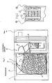
- a heating arrangement which comprises a reservoir 20 according to the invention and an oven 40, which are optionally in operative connection with each other via an optional lock module 30 or coupled.
- the reservoir 20 is spatially separated from the oven 40. From the reservoir 20 a discharge opening 12 leads as a single opening of the reservoir 20 in the lock module 30 and further into the oven 40, but it can also lead directly into the oven 40.
- the storage container 20 has a delivery unit with which fuels 17 can be conveyed to the furnace 40.
- This conveyor unit is formed according to the invention in the form of a flexible and flexible conveyor loop 1.
- the fuels 17 can be placed on this conveyor loop, as in Fig. 2 is shown.
- the conveyor loop is as in Fig. 2 represented, composed of two mutually spaced mutually parallel individual bands or chains.
- the conveyor loop 1 depending on the type or size of the fuel 17 also have a different shape, in particular, this can be configured as a one-piece wide mat or a wide band, in which case there is no gap between the individual bands.
- the conveyor loop 1 may also be formed as a chain or have a net-like structure.
- the conveyor loop 1 is not formed as an endless loop or endless belt, but has a defined length with a first end portion 60 and a second end portion 61.
- the conveyor loop 1 is at this first, the discharge opening 12 distant or furnace remote, end region 60 fixed or tension fixed to the inside of the upper cover of the reservoir 20 and fixedly attached to the upper surface of the support frame 21 and that at a mounting position or -axis 3 '.
- the conveyor loop 1 is mounted near the second end portion 61 on a deflection axis 4 or partially wound around this deflection axis 4, wherein the conveyor loop 1 experiences a deflection downwards by about 180 ° via the deflection axis 4.
- the conveyor loop 1 is thus mounted or suspended between the attachment position 3 'and the deflection axis 4 so that an intermediate, upwardly open discharge area 7 is formed, via which the fuels 17 from the conveyor loop 1 and subsequently through a discharge opening 12 in the direction of the oven 40 can be brought out.
- This upwardly open discharge area 7 extends between the attachment position 3 'and the deflection axis 4th
- the reservoir 20 is housed substantially in a housing which is bounded on both sides with side walls 22.
- the depth of the reservoir 20 is a few centimeters shorter than the depth of the combustion chamber to allow safe insertion.
- the billet is advantageously to be chosen in length so that it corresponds to the depth of the reservoir 20, ie it must be ensured that the firewood 17 and the firewood is stackable and as in Fig. 2 can be placed on the conveyor loop 1. Deviations of approx. 20% to the maximum length do not disturb the function. In order to exclude disturbances of the automatic conveyance, it is advantageous to sort out large and extremely shapeless piece of wood 17 or wood with protruding branches as well as too small or brittle wood in advance. Fuels, which have the usual dimensions and geometries, as they arise in the wood splitting of round and square timber, are suitable for the feed.
- At least one drive or traction means is further provided, with which the conveyor loop 1 can be moved or stretched or relaxed or with which the length of the conveyor loop 1 can be shortened or extended and their sag is reduced or increased , In this way, with appropriate movement of the drive or traction means of the bag-shaped cross-section or the barrel volume of the conveyor loop 1 and the fuels 17 are increased upward in the direction of the discharge area 7 towards. This process is reversible.
- a fixing position 3 ' arranged on the left side of the storage container 20 is provided, which is remote from the dispensing opening 12, and a deflection axis 4 close to the dispensing opening 12. These two positions 3', 4 define the size of the dispensing area 7.
- the right deflection axis 4 represents an upper discharge edge 19, which must overcome the fuels 17 in order to be discharged in the direction of the lock module 30 or to the oven 40.
- the attachment position 3 ' is relatively higher than the deflection axis 4 with respect to the conveyor loop 1. This predetermines the direction with which the fuels 17 can be removed from the conveyor loop 1, namely in the direction of the dispensing opening 12 via the dispensing edge 19.
- the conveyor loop 1 is completely loaded with fuel 17 and is present in its maximum sagging.
- the conveyor loop 1 forms a bag-like shape and depends down through. If fuel 17 is discharged from the conveyor loop 1 or train applied via the drive means, so reduces the cross-section, the capacity and the length of the conveyor loop 1 and the conveyor loop 1 takes a - not shown - reduced form with a smaller volume.
- the conveyor loop 1 forms a flat surface between the attachment position 3 'and the deflection axis 4. Fuels 17 can not hold on this inclined surface and automatically slide over the discharge edge 19 through the discharge opening 12 into the lock module 30.
- the oven-near deflection axis 4 can be either a freely rotatable deflection roller or a roller or a rigid smooth deflection bar, on which the conveyor loop 1 can slide along.
- the diverting axes may also be at least partially filled with adhesion improving agents, e.g. To be equipped teeth or protrusions to achieve a good operative connection or intervene in the chain especially when forming the conveyor loop 1 as a network or chain.
- the conveyor loop 1 can also run in, formed in the surface of the deflection axis 4, grooves or depressions and thereby be slightly raised above the edge of the grooves or depressions or protrude or have a greater thickness than the depth of the grooves.
- the deflection axis 4 is formed as the only drive or traction means of the conveyor loop 1 or driven by a motor.
- the drive of the conveyor loop 1 could also be done via a, possibly additional, independent drive, which attaches somewhere to the conveyor loop 1.
- a - not shown - height detector 6 is provided in the open output area 7 of the conveyor loop 1.
- This height detector 6 may be a mechanical or electronic, for example, equipped with light elements or sensors, detector. If the height detector 6 is triggered by the fuels 17 by the fuels 17 reaching a certain height in the discharge area 7, the movement of the conveyor loop 1 and / or the drive or the traction means is stopped or reversed for a certain time.
- the fuels 17 can be discharged from the storage container 20 via a delivery opening 12 located at the top right in the storage container 20.
- a lock module 30 is arranged, in which a system of flaps or rotary valves or fire protection, smoke protection and / or metering flaps 50 is arranged for the fuel 17.
- the flaps are smoke-tight or insulated against exhaust gases and close tightly, so that no exhaust gases can escape from the furnace 40 in the direction of the reservoir 20.
- the combustion chamber or the combustion chamber 25 of the furnace 40 In the area below the lock module 30 is the combustion chamber or the combustion chamber 25 of the furnace 40.
- fuels 17 rest on a grate 14 and can be ignited there via an ignition, in particular an automatic ignition.
- a level detector 13 may be provided, which indicates how much fuel 17 is present in the combustion chamber 25.
- This level detector 13 is connected to the control of the reservoir 20, in particular with the control of the conveyor loop 1. When the level detector 13 is triggered, the movement of the conveyor loop 1 is stopped or vice versa.
- a heat exchanger 11 is attached, which is heated by the heat of the combustion chamber.
- an overload protection can be provided in the event that it comes to a wedging.
- the power consumption is monitored, which is required for the movement of the conveyor loop 1.
- wedging the conveyor loop 1 can no longer promote or encounters a resistance. If the limit of the monitored current consumption is exceeded, then a stop or a reversal of the motor rotation direction or the movement of the conveyor loop 1 is initiated, whereby the wedging can be effectively eliminated.
- the storage container 20 is larger by a multiple and has a larger volume than the combustion chambers 25th
- a three interconnected straight plate-shaped plates existing rectangular support frame 21 is provided in the reservoir 29. This surrounds the conveyor loop 1 outside and limits laterally and down the maximum sag of the conveyor loop 1 and is the maximum size of the conveyor loop. 1 in front. Alternatively, a lower support plate may be provided which supports the conveyor loop 1 only down and limits their maximum sag down.
- a part of the support frame 21 also extends into the discharge area 7 above the fuel 17. At this horizontally extending part of the support frame, the first end portion 60 and the contact position 3 'is arranged or there, the conveyor loop 1 is fixed.
- the side edges of the support frame 21 are welded to both side walls 22 of the reservoir 20. Thus, it simultaneously determines the depth or width of the reservoir 20.
- the initial operation of the heating arrangement with the reservoir 20 and the promotion of fuel 17 to the furnace 40 is in practice as follows: About a Gree the conveyor loop 1 with fuel, especially logs 17, loaded. The filling door is then closed. Now comes from the furnace control the signal that heating material is needed, so raises the conveyor loop 1 and their sagging is reduced. This is done by activating the motor-driven deflection roller 4. This fires the firewood 17 with it until it falls through the discharge opening 12 via the discharge edge 19. If the fuel reaches the maximum limited height 17, the height detector 6 is triggered and the movement of the guide roller 4 is stopped or even vice versa.
- the supply of the fuel 17 from the reservoir 20 into the combustion chamber 25 of the furnace 40 takes place automatically depending on the energy requirement.
- the efficiency of such systems increases as the control of the furnace 40 operates in an optimal combustion process with a defined amount of fuel. Overcrowding is excluded here. An otherwise in such solid fuel stoves necessary "stinking" of the combustion with energy surplus is eliminated. This has an advantageous effect on the efficiency, the exhaust gas values and on the maintenance intervals of such systems.
- Fig. 3 is a further embodiment shown in which in the uppermost region of the reservoir 20 and above the fuels 17 and above or in the output area (s) 7, a pressure element 70 is arranged.
- This pressure element 70 presses or pressurized moved from the conveyor loop 1 upwards and in the Area of action of the pressure element 70 reaching fuel 17 in the direction of the discharge opening 12 and in the direction of the oven 40 and possibly even beyond the discharge edge 19 away.
- the pressure element 70 is designed drive-free without a motor and is only moved by a bottom of the fuels 17 upward force. Furthermore, the pressure element 70 is movable independently of the conveyor loop 1 and / or the deflection axis 4.
- the pressure element 70 has at least one pressure bar 71, which finally detects the fuels 17 and exerts a sufficient pressure on the fuels 17 due to its own mass.
- the net mass of the pressure bar 71 thus contributes to the promotion or movement of the fuels in the desired direction or exerts the required impulse on the woods.
- the pressure bar 71 advantageously extends over a substantial portion of the longitudinal extent of the reservoir 20, whereby it can also detect several woods simultaneously at different positions.
- the surface 74 of the lower side edge of the pressure beam 71 is patterned or hooked to assist in the promotion of the fuels 17 in the desired direction.
- the pressure bar 71 is freely swinging or oscillating with a horizontal movement component, wherein the pressure bar 71 according to FIG Fig. 3 parallelogram-like swinging, and is constantly aligned parallel to the top of the reservoir or the support frame 21 and horizontally.
- the pressure bar 71 is fastened via two braces 72, 73 by means of joints 75 to the inner surface of the upper side of the storage container 20 or of the support frame 21 and can thereby carry out the relevant movement.
- the movement of the pressure bar 71 is composed of a horizontal and a vertical component, wherein the horizontal component, the fuel 17 is conveyed in the direction of the discharge opening 12 or moves and the vertical upward component, the fuels 17 even slightly raises or does not push down , This rocking movement effectively prevents wedging of the fuels 17 and any wedges are dissolved again. In this way, individual logs in the top row can even roll over each other in the direction of the discharge opening 12 or rolled.
- the pressure bar 71 is aligned parallel to the side walls 22 of the storage container 20 or parallel to the plane spanned by the conveyor loop 1 and its movement is also parallel to these side walls 22 and parallel to plane spanned by the conveyor loop 1 or normal to the orientation of the logs resting on the conveyor loop 1.
- a stop element 76 is arranged, which limits the one of the discharge opening 12 directed away movement of the pressure element 70 and the pressure bar 71 to the left on one side.
- the pressure element 70 or the pressure bar 71 is thereby given an initial position with increased potential energy which is unequal or is deflected from the rest position in the direction of the dispensing opening 12. Also, the direction in which the pressure bar 71 can move, as soon as a force acts on it from below, is defined by it.
- the pressure element 70 works so that the fuel 17 is lifted from below through the conveyor loop 1 and enters the sphere of action of the pressure element 70. The fuel 17 then abuts the pressure bar 71, exerts a force on it and raises it slightly or deflects it in the predetermined direction to the right. The pressure element 70 or the pressure bar 71 deviates or is now lifted by the movement of the fuel 17 and offset to the right or deflected to the right above in the direction of the discharge opening 12.
- the fuel materials 17 are taken or the fuel materials 17 are a horizontal and a vertical force or are offset and slightly raised. This is usually sufficient to transport the fuels 17 to the discharge opening 12 or even to allow the fuels 17 to roll directly over the discharge edge 19.
Landscapes
- Engineering & Computer Science (AREA)
- Chemical & Material Sciences (AREA)
- Combustion & Propulsion (AREA)
- Mechanical Engineering (AREA)
- General Engineering & Computer Science (AREA)
- Solid-Fuel Combustion (AREA)
Applications Claiming Priority (1)
| Application Number | Priority Date | Filing Date | Title |
|---|---|---|---|
| AT4622008A AT506306B1 (de) | 2008-03-25 | 2008-03-25 | Vorratsbehälter für feste brennstoffe |
Publications (1)
| Publication Number | Publication Date |
|---|---|
| EP2105666A2 true EP2105666A2 (fr) | 2009-09-30 |
Family
ID=40718678
Family Applications (1)
| Application Number | Title | Priority Date | Filing Date |
|---|---|---|---|
| EP20090450058 Withdrawn EP2105666A2 (fr) | 2008-03-25 | 2009-03-12 | Récipient de stockage pour combustibles solides |
Country Status (2)
| Country | Link |
|---|---|
| EP (1) | EP2105666A2 (fr) |
| AT (1) | AT506306B1 (fr) |
Cited By (1)
| Publication number | Priority date | Publication date | Assignee | Title |
|---|---|---|---|---|
| EP3677157A1 (fr) * | 2019-01-05 | 2020-07-08 | Traeger Pellet Grills, LLC | Barbecues à granulés ayant des systèmes de détection de niveau de granulés et procédés associés |
Families Citing this family (1)
| Publication number | Priority date | Publication date | Assignee | Title |
|---|---|---|---|---|
| IT1399708B1 (it) * | 2010-04-26 | 2013-04-26 | Nordica Spa | Apparecchio riscaldante a combustibile solido con alimentazione automatica ad elevata sicurezza |
Citations (4)
| Publication number | Priority date | Publication date | Assignee | Title |
|---|---|---|---|---|
| US4539915A (en) | 1983-09-14 | 1985-09-10 | Francis Bouron | Automatic feed device for solid fuel boiler, specifically for logs of wood |
| FR2668581A1 (fr) | 1990-10-26 | 1992-04-30 | Clement Pascal | Distributeur de buches pour l'alimentation des chaudieres a bois. |
| AT399388B (de) | 1992-10-20 | 1995-04-25 | Hofbauer Fritz | Ofen bzw. kessel für feste brennstoffe, insbesondere holz |
| WO2007140491A1 (fr) | 2006-06-09 | 2007-12-13 | Guetl Karl | Réservoir de stockage et four |
-
2008
- 2008-03-25 AT AT4622008A patent/AT506306B1/de not_active IP Right Cessation
-
2009
- 2009-03-12 EP EP20090450058 patent/EP2105666A2/fr not_active Withdrawn
Patent Citations (4)
| Publication number | Priority date | Publication date | Assignee | Title |
|---|---|---|---|---|
| US4539915A (en) | 1983-09-14 | 1985-09-10 | Francis Bouron | Automatic feed device for solid fuel boiler, specifically for logs of wood |
| FR2668581A1 (fr) | 1990-10-26 | 1992-04-30 | Clement Pascal | Distributeur de buches pour l'alimentation des chaudieres a bois. |
| AT399388B (de) | 1992-10-20 | 1995-04-25 | Hofbauer Fritz | Ofen bzw. kessel für feste brennstoffe, insbesondere holz |
| WO2007140491A1 (fr) | 2006-06-09 | 2007-12-13 | Guetl Karl | Réservoir de stockage et four |
Cited By (1)
| Publication number | Priority date | Publication date | Assignee | Title |
|---|---|---|---|---|
| EP3677157A1 (fr) * | 2019-01-05 | 2020-07-08 | Traeger Pellet Grills, LLC | Barbecues à granulés ayant des systèmes de détection de niveau de granulés et procédés associés |
Also Published As
| Publication number | Publication date |
|---|---|
| AT506306B1 (de) | 2009-08-15 |
| AT506306A4 (de) | 2009-08-15 |
Similar Documents
| Publication | Publication Date | Title |
|---|---|---|
| DE1556165C3 (de) | Vorrichtung zur Bewegungssteuerung einzelner Gegenstande auf einem Sam melförderer | |
| EP2027414A1 (fr) | Réservoir de stockage et four | |
| AT506306B1 (de) | Vorratsbehälter für feste brennstoffe | |
| EP2005820B1 (fr) | Porte, comme en particulier une porte d'entrée d'une boîte de ramassage automatique pour animaux | |
| AT506321B1 (de) | Vorratsbehälter für feste brennstoffe mit druckelement | |
| CH703513B1 (de) | Ofen für granulatförmiges Brenngut, für Leistungen bis hinunter zu weniger als 1 kW, mit Einrichtung für die Brenngutzufuhr sowie die Aschenzerkleinerung und -verteilung. | |
| DE2012615A1 (de) | Schubvorrichtung für Gefrieranlagen | |
| EP4019441A2 (fr) | Silo pourvu d'une unité de détection de pression, procédé de commande d'un transport de matieres et utilisation d'une unité de détection de pression | |
| DE102010005796A1 (de) | Anlage zur automatischen Förderung von Scheitholz aus einem Bunker bzw. Vorratsbehälter mit nachgeschalteter Vereinzelung zur Beschickung eines Scheitholzkessels | |
| DE102015105645B4 (de) | Vorrichtung zur Förderung von Kugeln | |
| EP2105660A2 (fr) | Système d'écluses | |
| DE102008047900B4 (de) | Vorrichtung für die Lagerung von Schüttgut | |
| DE102011017497A1 (de) | Lager- und/oder Transportbehälter für Schüttgut | |
| EP1564162B1 (fr) | Dispositif de transport vertical | |
| DE3124928C2 (de) | Vertikalförderer, insbesondere für Halm- und Blattgut | |
| DE1116599B (de) | Vorrichtung zum Abbauen eines Stueckgutstapels | |
| EP0251258A2 (fr) | Dispositif d'alimentation en bois fragmenté pour chaudière | |
| DE3037075C2 (de) | Brennstoff-Fördereinrichtung für eine Rostfeuerung | |
| AT239138B (de) | Vorrichtung in einer Dungförderanlage zum Kuppeln zweier Schubstangen | |
| DE202008004405U1 (de) | Schleusensystem | |
| AT53495B (de) | Wagenschiebevorrichtung, insbesondere zum Beladen der Förderkörbe von Schachtanlagen. | |
| AT249588B (de) | Silo | |
| EP4119760A1 (fr) | Portail à enroulement rapide | |
| AT324949B (de) | Fördergerät | |
| AT354356B (de) | Foerdereinrichtung |
Legal Events
| Date | Code | Title | Description |
|---|---|---|---|
| PUAI | Public reference made under article 153(3) epc to a published international application that has entered the european phase |
Free format text: ORIGINAL CODE: 0009012 |
|
| AK | Designated contracting states |
Kind code of ref document: A2 Designated state(s): AT BE BG CH CY CZ DE DK EE ES FI FR GB GR HR HU IE IS IT LI LT LU LV MC MK MT NL NO PL PT RO SE SI SK TR |
|
| AX | Request for extension of the european patent |
Extension state: AL BA RS |
|
| STAA | Information on the status of an ep patent application or granted ep patent |
Free format text: STATUS: THE APPLICATION IS DEEMED TO BE WITHDRAWN |
|
| 18D | Application deemed to be withdrawn |
Effective date: 20121002 |