EP2105684A2 - Vanne de contrôle de la pression - Google Patents
Vanne de contrôle de la pression Download PDFInfo
- Publication number
- EP2105684A2 EP2105684A2 EP20090156096 EP09156096A EP2105684A2 EP 2105684 A2 EP2105684 A2 EP 2105684A2 EP 20090156096 EP20090156096 EP 20090156096 EP 09156096 A EP09156096 A EP 09156096A EP 2105684 A2 EP2105684 A2 EP 2105684A2
- Authority
- EP
- European Patent Office
- Prior art keywords
- valve
- pressure control
- control valve
- main body
- disc spring
- Prior art date
- Legal status (The legal status is an assumption and is not a legal conclusion. Google has not performed a legal analysis and makes no representation as to the accuracy of the status listed.)
- Withdrawn
Links
- 230000001105 regulatory effect Effects 0.000 abstract description 13
- 238000004519 manufacturing process Methods 0.000 abstract description 8
- 239000003507 refrigerant Substances 0.000 abstract description 7
- 238000005057 refrigeration Methods 0.000 abstract description 7
- 230000006835 compression Effects 0.000 abstract description 4
- 238000007906 compression Methods 0.000 abstract description 4
- 238000003466 welding Methods 0.000 description 6
- 239000012530 fluid Substances 0.000 description 5
- 238000004378 air conditioning Methods 0.000 description 2
- 230000001276 controlling effect Effects 0.000 description 1
- 230000000694 effects Effects 0.000 description 1
- 239000002184 metal Substances 0.000 description 1
Images


Classifications
-
- F—MECHANICAL ENGINEERING; LIGHTING; HEATING; WEAPONS; BLASTING
- F25—REFRIGERATION OR COOLING; COMBINED HEATING AND REFRIGERATION SYSTEMS; HEAT PUMP SYSTEMS; MANUFACTURE OR STORAGE OF ICE; LIQUEFACTION SOLIDIFICATION OF GASES
- F25B—REFRIGERATION MACHINES, PLANTS OR SYSTEMS; COMBINED HEATING AND REFRIGERATION SYSTEMS; HEAT PUMP SYSTEMS
- F25B41/00—Fluid-circulation arrangements
- F25B41/30—Expansion means; Dispositions thereof
- F25B41/31—Expansion valves
- F25B41/33—Expansion valves with the valve member being actuated by the fluid pressure, e.g. by the pressure of the refrigerant
- F25B41/335—Expansion valves with the valve member being actuated by the fluid pressure, e.g. by the pressure of the refrigerant via diaphragms
-
- F—MECHANICAL ENGINEERING; LIGHTING; HEATING; WEAPONS; BLASTING
- F25—REFRIGERATION OR COOLING; COMBINED HEATING AND REFRIGERATION SYSTEMS; HEAT PUMP SYSTEMS; MANUFACTURE OR STORAGE OF ICE; LIQUEFACTION SOLIDIFICATION OF GASES
- F25B—REFRIGERATION MACHINES, PLANTS OR SYSTEMS; COMBINED HEATING AND REFRIGERATION SYSTEMS; HEAT PUMP SYSTEMS
- F25B2600/00—Control issues
- F25B2600/17—Control issues by controlling the pressure of the condenser
-
- Y—GENERAL TAGGING OF NEW TECHNOLOGICAL DEVELOPMENTS; GENERAL TAGGING OF CROSS-SECTIONAL TECHNOLOGIES SPANNING OVER SEVERAL SECTIONS OF THE IPC; TECHNICAL SUBJECTS COVERED BY FORMER USPC CROSS-REFERENCE ART COLLECTIONS [XRACs] AND DIGESTS
- Y10—TECHNICAL SUBJECTS COVERED BY FORMER USPC
- Y10T—TECHNICAL SUBJECTS COVERED BY FORMER US CLASSIFICATION
- Y10T137/00—Fluid handling
- Y10T137/7722—Line condition change responsive valves
- Y10T137/7738—Pop valves
Definitions
- the present invention relates to a pressure control valve, and more particularly to a pressure control valve used in a refrigeration cycle or the like used in refrigeration and air conditioning relations.
- a pressure control valve is used for controlling pressure of a refrigerant.
- a vapor compression type refrigeration cycle circulating a refrigerant in a closed circuit constructed by a compressor, a radiator, a pressure control valve (an expansion valve), an evaporator and the like is used in an air conditioning apparatus for a vehicle.
- Patent Document 1 describes a pressure control valve which is provided with a body having a refrigerant flow path extending from an internal heat exchanger to an evaporator via a valve port, a valve seat set within the refrigerant flow path, a valve body provided within the body to move close to and away from the valve seat, a diaphragm fixed to one end of the valve body, a lid body and a lower support portion forming a sealed space above the diaphragm, a spring attaching portion set in the other end of the valve body, a spring interposed between the spring attaching portion and the valve seat, and the like.
- valve closing force of the valve body is obtained by internal pressure within the sealed space formed above the diaphragm fixed to one end of the valve body, and the spring interposed between the valve seat and the spring attaching portion of the valve body, and valve opening force of the valve body is obtained by pressure of the refrigerant from the internal heat exchanger. Further, valve close and valve open states are switched by balance between the valve closing force and the valve opening force.
- Patent Document 1 Japanese Unexamined Patent Publication No. 2007-139209
- valve closing force with respect to a valve body is obtained only by a coil spring for energizing the valve body in a direction toward a valve seat, however, a space for attaching the coil spring is necessary in the pressure control valve mentioned above, and there is a problem that it is unavoidable to enlarge the valve in size.
- the present invention is made by taking the problem in the prior art mentioned above into consideration, and an object of the present invention is to provide a pressure control valve in which a valve main body can be downsized, a manufacturing cost is low, and a pressure control characteristic or the like can be easily regulated.
- the present invention is a pressure control valve comprising:
- the disc spring is used for energizing the valve body in the direction toward the valve seat, it is possible to lessen a dimension of the valve main body in a direction of the valve body movement, and it is possible to downsize the valve main body. Further, since the disc spring which is a general purpose part can be used, it is possible to reduce the manufacturing cost of the valve. Further, since the disc spring has a high spring rigidity, the disc spring can be preferably used in the vapor compression type refrigeration cycle or the like circulating a high-pressure refrigerant.
- a plurality of the disc springs can be placed.
- a plurality of the disc springs can be placed in parallel. Accordingly, it is possible to provide a pressure regulating valve having high working pressure while a stroke of the valve body is made small.
- a plurality of the disc springs can be layered in series. Accordingly, it is possible to provide a pressure regulating valve having a large stroke while working pressure is kept approximately constant.
- the pressure control valve in which the valve main body can be downsized, the manufacturing cost is low, and the pressure control characteristic or the like can be easily regulated.
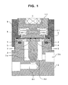
- Fig. 1 shows a first embodiment of a pressure control valve in accordance with the present invention.
- the pressure control valve 1 is, broadly speaking, constructed by a valve main body 2 having a valve chamber 2a in an internal portion, a valve body 3 moving close to and away from a valve seat 2d within the valve chamber 2a, an annular receiving member 5 mounted on a top surface of the valve main body 2 via an 0-ring 4, a diaphragm 6 supported by the receiving member 5 at its lower surface and interposed between the valve body 3 and a pressing member 8, a plurality of (three) disc springs 11 arranged above the pressing member 8 for energizing the pressing member 8 downward, a regulating screw 12 for regulating elastic force of the disc springs 11 to the pressing member 8, and the like.
- the diaphragm 6 is fixed by the valve body 3 and the receiving member 5 via a fixing means 7 such as welding or the like.
- valve main body 2 is screwed with a lid body 9 at its top portion, and the lid body 9 hold the diaphragm 6 between itself and the annular receiving member 5.
- a valve seat 2d being able to communicate with a flow path 2c is formed at a bottom portion of the valve chamber 2a.
- a conical lower end portion of the valve body 3 moves close to and away from the valve seat 2d, and thereby an opening of the valve seat 2d is closed and opened.
- the diaphragm 6 is formed by an elastic body made of a metal or the like, and is structured such that, when fluid pressure in the valve chamber 2a rises, the diaphragm is elastically deformed and the valve body 3 is movable upward.
- the pressing member 8 in contact with the diaphragm 6, the disc springs 11 and the regulating screw 12 are accommodated within the lid body 9.
- the pressing member 8 contacts with the diaphragm 6 at its lower surface, and the disc springs 11 are installed to a protruding portion at an upper portion thereof.
- Three disc springs 11 are layered in series at the upper portion of the pressing member 8.
- the regulating screw 12 is provided for regulating the energizing force of the disc springs 11, and is engaged with the top portion of the lid body 9. It is possible to regulate the energizing force of the disc springs 11 by relatively moving the regulating screw with respect to the lid body 9.
- Fig. 1 shows a state in which the pressure control valve 1 is closed. Since the valve body 3 contacts with the valve seat 2d in this state, fluid does not flow from the flow path 2b to the flow path 2c.
- a pressure control valve 21 is structured such as to have a valve main body 22 obtained by integrally forming the valve main body 2 and the receiving member 5 of the pressure control valve 1 shown in Fig. 1 .
- a valve main body 22 obtained by integrally forming the valve main body 2 and the receiving member 5 of the pressure control valve 1 shown in Fig. 1 .
- a pressure control valve 31 is provided with a diaphragm 32 formed in a closed-end cylindrical shape, and a lid body 33 and a valve main body 34 holding the diaphragm 32 therebetween in place of the diaphragm 6, the lid body 9 and the valve main body 22 of the pressure control valve 21 shown in Fig. 3 , and the 0-ring 4 is arranged at a side surface of the valve main body 34. Accordingly, since it is not necessary to fix the diaphragm 32 to the valve main body 34 by welding or the like similarly to the pressure control valve 21 in Fig. 3 , it is possible to reduce the number of parts and man hours. Further, since the diaphragm 32 is formed in the closed-end cylindrical shape, it is possible to improve airtightness. In this case, since the action of the pressure control valve 31 is the same as that of the pressure control valve 1 mentioned above, a description thereof will be omitted.
- a pressure control valve 41 is provided with a coil spring 42 for energizing the valve body 3 toward the diaphragm 6 side, in addition to the structure of the pressure control valve 21 shown in Fig. 3 . Accordingly, it is not necessary to fix the valve body 3 and the diaphragm 6 by welding or the like, and it is not necessary to fix the diaphragm 6 and the valve main body 22 by welding or the like, so that any equipment for welding or the like is not necessary for manufacturing the pressure control valve. In this case, since the action of the pressure control valve 41 is the same as the pressure control valve 1, a description thereof will be omitted.
- the layering number of the disc springs 11 can be appropriately changed in correspondence to a desired valve body stroke and working pressure.
- a direction of placing the disc springs 11 they may be layered in series such as an example shown in Fig. 1 , and may be placed in parallel. It is possible to enlarge the stroke of the valve body 3 while the working pressure is kept approximately constant, by layering the disc springs 11 in series. Further, in the case that the disc springs 11 are placed in parallel, it is possible to increase the working pressure while the stroke of the valve body 3 is made small.
Landscapes
- Physics & Mathematics (AREA)
- Engineering & Computer Science (AREA)
- Fluid Mechanics (AREA)
- Mechanical Engineering (AREA)
- Thermal Sciences (AREA)
- General Engineering & Computer Science (AREA)
- Control Of Fluid Pressure (AREA)
- Safety Valves (AREA)
- Fluid-Driven Valves (AREA)
Applications Claiming Priority (1)
| Application Number | Priority Date | Filing Date | Title |
|---|---|---|---|
| JP2008080003A JP2009236147A (ja) | 2008-03-26 | 2008-03-26 | 圧力制御弁 |
Publications (2)
| Publication Number | Publication Date |
|---|---|
| EP2105684A2 true EP2105684A2 (fr) | 2009-09-30 |
| EP2105684A3 EP2105684A3 (fr) | 2010-08-25 |
Family
ID=40851977
Family Applications (1)
| Application Number | Title | Priority Date | Filing Date |
|---|---|---|---|
| EP20090156096 Withdrawn EP2105684A3 (fr) | 2008-03-26 | 2009-03-25 | Vanne de contrôle de la pression |
Country Status (4)
| Country | Link |
|---|---|
| US (1) | US20090242041A1 (fr) |
| EP (1) | EP2105684A3 (fr) |
| JP (1) | JP2009236147A (fr) |
| CN (1) | CN101545551A (fr) |
Families Citing this family (9)
| Publication number | Priority date | Publication date | Assignee | Title |
|---|---|---|---|---|
| WO2010114061A1 (fr) | 2009-03-31 | 2010-10-07 | 三菱化学株式会社 | Substance luminescente, procédé de fabrication de la substance luminescente, composition contenant la substance luminescente, dispositif émettant de la lumière, dispositif d'éclairage et dispositif d'affichage d'images |
| CN102052292A (zh) * | 2011-01-18 | 2011-05-11 | 无锡市凯龙汽车设备制造有限公司 | 用于计量泵的压力调节阀 |
| US9377114B2 (en) * | 2012-04-25 | 2016-06-28 | Nordson Corporation | Pressure control valve for reactive adhesives |
| CN103322249A (zh) * | 2013-06-26 | 2013-09-25 | 无锡商业职业技术学院 | 直动式顺序阀 |
| CN106490984B (zh) * | 2016-11-25 | 2020-07-31 | 泰州乐金电子冷机有限公司 | 冰箱用饮水机 |
| CN111396599B (zh) * | 2020-03-23 | 2021-10-26 | 浙江农林大学暨阳学院 | 一种流量控制阀 |
| CN111365911B (zh) * | 2020-03-23 | 2021-10-29 | 浙江农林大学暨阳学院 | 一种膨胀阀及汽车空调系统 |
| CN111219533B (zh) * | 2020-03-23 | 2021-10-26 | 浙江农林大学暨阳学院 | 一种热力膨胀阀及汽车空调系统 |
| JP7483250B2 (ja) | 2020-05-26 | 2024-05-15 | 株式会社不二工機 | 膨張弁 |
Citations (5)
| Publication number | Priority date | Publication date | Assignee | Title |
|---|---|---|---|---|
| JPH0590825A (ja) | 1991-09-30 | 1993-04-09 | Nec Corp | アンテナ角度調整装置 |
| WO2004038310A1 (fr) | 2002-10-26 | 2004-05-06 | Danfoss A/S | Detendeur pour systemes de refrigeration haute pression |
| EP1722143A1 (fr) | 2005-05-12 | 2006-11-15 | Behr GmbH & Co. KG | Soupape à pression différentielle |
| JP2007139209A (ja) | 2005-11-14 | 2007-06-07 | Denso Corp | 冷凍サイクル用圧力制御弁 |
| JP2007315727A (ja) | 2006-05-29 | 2007-12-06 | Tgk Co Ltd | 膨張弁 |
Family Cites Families (15)
| Publication number | Priority date | Publication date | Assignee | Title |
|---|---|---|---|---|
| US2704548A (en) * | 1955-03-22 | Disk spring support for valve diaphragm | ||
| US3217740A (en) * | 1962-03-23 | 1965-11-16 | Bendix Corp | Relief valve having partial balancing arrangement |
| US3884260A (en) * | 1972-02-01 | 1975-05-20 | Johnson Service Co | Diaphragm valve apparatus and control systems employing such valve apparatus |
| US4243070A (en) * | 1978-08-16 | 1981-01-06 | Jackson Samuel G | Variable back pressure valve |
| US4203465A (en) * | 1979-03-27 | 1980-05-20 | General Motors Corporation | Precision pressure control valve |
| US5137003A (en) * | 1989-05-19 | 1992-08-11 | Mitsubishi Denki K.K. | Supercharged pressure control valve apparatus |
| JPH06337077A (ja) * | 1993-05-27 | 1994-12-06 | Nanomaizaa Kk | 安全弁 |
| DE10058515A1 (de) * | 2000-11-24 | 2002-05-29 | Obrist Engineering Gmbh Lusten | Überdruckventil |
| US7744071B2 (en) * | 2001-06-19 | 2010-06-29 | Mercer Valve Company, Inc. | Safety relief valve having a low blow-down value and spring therefore |
| US6708712B2 (en) * | 2001-10-04 | 2004-03-23 | Illinois Tool Works Inc. | Pressure regulator utilizing a disc spring |
| JP2003254201A (ja) * | 2002-03-01 | 2003-09-10 | Mitsuba Corp | 圧力制御装置 |
| CN2809871Y (zh) * | 2005-04-20 | 2006-08-23 | 中国电力科学研究院 | 晶闸管安装的碟簧压紧机构 |
| JP2007092918A (ja) * | 2005-09-29 | 2007-04-12 | Nissan Tanaka Corp | 背圧弁 |
| JP4781845B2 (ja) * | 2006-02-27 | 2011-09-28 | 日酸Tanaka株式会社 | 圧力調整弁 |
| JP2009008183A (ja) * | 2007-06-28 | 2009-01-15 | Maruyama Mfg Co Ltd | 調圧弁 |
-
2008
- 2008-03-26 JP JP2008080003A patent/JP2009236147A/ja active Pending
-
2009
- 2009-03-24 US US12/382,777 patent/US20090242041A1/en not_active Abandoned
- 2009-03-25 EP EP20090156096 patent/EP2105684A3/fr not_active Withdrawn
- 2009-03-25 CN CN200910129768A patent/CN101545551A/zh active Pending
Patent Citations (5)
| Publication number | Priority date | Publication date | Assignee | Title |
|---|---|---|---|---|
| JPH0590825A (ja) | 1991-09-30 | 1993-04-09 | Nec Corp | アンテナ角度調整装置 |
| WO2004038310A1 (fr) | 2002-10-26 | 2004-05-06 | Danfoss A/S | Detendeur pour systemes de refrigeration haute pression |
| EP1722143A1 (fr) | 2005-05-12 | 2006-11-15 | Behr GmbH & Co. KG | Soupape à pression différentielle |
| JP2007139209A (ja) | 2005-11-14 | 2007-06-07 | Denso Corp | 冷凍サイクル用圧力制御弁 |
| JP2007315727A (ja) | 2006-05-29 | 2007-12-06 | Tgk Co Ltd | 膨張弁 |
Also Published As
| Publication number | Publication date |
|---|---|
| CN101545551A (zh) | 2009-09-30 |
| EP2105684A3 (fr) | 2010-08-25 |
| JP2009236147A (ja) | 2009-10-15 |
| US20090242041A1 (en) | 2009-10-01 |
Similar Documents
| Publication | Publication Date | Title |
|---|---|---|
| EP2105684A2 (fr) | Vanne de contrôle de la pression | |
| US7036527B2 (en) | Composite valve | |
| US10309702B2 (en) | Control valve | |
| US10436484B2 (en) | Caulking fixation type power element and expansion valve using the same | |
| CN103671033A (zh) | 感压控制阀 | |
| JP2017198387A (ja) | 膨張弁 | |
| CN110779246B (zh) | 使用形状记忆合金弹簧的膨胀阀和使用该膨胀阀的车辆空调系统 | |
| US20190003754A1 (en) | Expansion valve | |
| CN111868461B (zh) | 动力元件以及具有该动力元件的膨胀阀 | |
| JP2010112616A (ja) | 温度式膨張弁 | |
| WO2018030116A1 (fr) | Détendeur | |
| JP2017040426A (ja) | 制御弁 | |
| JPWO2006090826A1 (ja) | 圧力制御弁 | |
| JP2018025331A (ja) | 膨張弁 | |
| KR20140076507A (ko) | 제어 밸브 | |
| JP2008138812A (ja) | 差圧弁 | |
| EP3070566A1 (fr) | Valve réductrice de pression | |
| KR20170042008A (ko) | 에어컨디셔너용 팽창밸브 | |
| KR101698756B1 (ko) | 히트펌프 시스템의 냉매량 조절장치 | |
| JP5249701B2 (ja) | 圧力式膨張弁 | |
| JP4077308B2 (ja) | 膨張弁 | |
| JP2021055769A (ja) | バルブ装置及びバルブ装置を用いたマスフローコントローラ | |
| US10900530B2 (en) | Expansion valve | |
| JP4509000B2 (ja) | 圧力制御弁 | |
| JP4641190B2 (ja) | 可変容量型圧縮機用制御弁 |
Legal Events
| Date | Code | Title | Description |
|---|---|---|---|
| PUAI | Public reference made under article 153(3) epc to a published international application that has entered the european phase |
Free format text: ORIGINAL CODE: 0009012 |
|
| AK | Designated contracting states |
Kind code of ref document: A2 Designated state(s): AT BE BG CH CY CZ DE DK EE ES FI FR GB GR HR HU IE IS IT LI LT LU LV MC MK MT NL NO PL PT RO SE SI SK TR |
|
| AX | Request for extension of the european patent |
Extension state: AL BA RS |
|
| PUAL | Search report despatched |
Free format text: ORIGINAL CODE: 0009013 |
|
| AK | Designated contracting states |
Kind code of ref document: A3 Designated state(s): AT BE BG CH CY CZ DE DK EE ES FI FR GB GR HR HU IE IS IT LI LT LU LV MC MK MT NL NO PL PT RO SE SI SK TR |
|
| AX | Request for extension of the european patent |
Extension state: AL BA RS |
|
| 17P | Request for examination filed |
Effective date: 20110225 |
|
| AKX | Designation fees paid |
Designated state(s): DE FR IT |
|
| 17Q | First examination report despatched |
Effective date: 20111129 |
|
| GRAP | Despatch of communication of intention to grant a patent |
Free format text: ORIGINAL CODE: EPIDOSNIGR1 |
|
| INTG | Intention to grant announced |
Effective date: 20150220 |
|
| STAA | Information on the status of an ep patent application or granted ep patent |
Free format text: STATUS: THE APPLICATION IS DEEMED TO BE WITHDRAWN |
|
| 18D | Application deemed to be withdrawn |
Effective date: 20150703 |