EP2105708B1 - Straßenformeinschätzungsvorrichtung, Straßenformeinschätzungsverfahren und Programm - Google Patents
Straßenformeinschätzungsvorrichtung, Straßenformeinschätzungsverfahren und Programm Download PDFInfo
- Publication number
- EP2105708B1 EP2105708B1 EP09004261.5A EP09004261A EP2105708B1 EP 2105708 B1 EP2105708 B1 EP 2105708B1 EP 09004261 A EP09004261 A EP 09004261A EP 2105708 B1 EP2105708 B1 EP 2105708B1
- Authority
- EP
- European Patent Office
- Prior art keywords
- corner
- shape
- road
- point
- shape interpolation
- Prior art date
- Legal status (The legal status is an assumption and is not a legal conclusion. Google has not performed a legal analysis and makes no representation as to the accuracy of the status listed.)
- Not-in-force
Links
- 238000000034 method Methods 0.000 title claims description 19
- 238000012545 processing Methods 0.000 claims description 258
- 238000004364 calculation method Methods 0.000 claims description 42
- 238000001514 detection method Methods 0.000 claims description 33
- 239000006185 dispersion Substances 0.000 claims description 12
- 238000010586 diagram Methods 0.000 description 44
- 230000005540 biological transmission Effects 0.000 description 11
- 230000008569 process Effects 0.000 description 8
- 238000004891 communication Methods 0.000 description 6
- 230000015572 biosynthetic process Effects 0.000 description 3
- 238000000605 extraction Methods 0.000 description 3
- 230000006870 function Effects 0.000 description 3
- 230000015654 memory Effects 0.000 description 3
- 230000008859 change Effects 0.000 description 2
- 230000009189 diving Effects 0.000 description 2
- 230000001419 dependent effect Effects 0.000 description 1
- 238000011161 development Methods 0.000 description 1
- 230000018109 developmental process Effects 0.000 description 1
- 239000003550 marker Substances 0.000 description 1
- 238000012986 modification Methods 0.000 description 1
- 230000004048 modification Effects 0.000 description 1
- 230000003287 optical effect Effects 0.000 description 1
- 238000004088 simulation Methods 0.000 description 1
- 238000003786 synthesis reaction Methods 0.000 description 1
- 230000003936 working memory Effects 0.000 description 1
Images





Classifications
-
- G—PHYSICS
- G01—MEASURING; TESTING
- G01C—MEASURING DISTANCES, LEVELS OR BEARINGS; SURVEYING; NAVIGATION; GYROSCOPIC INSTRUMENTS; PHOTOGRAMMETRY OR VIDEOGRAMMETRY
- G01C21/00—Navigation; Navigational instruments not provided for in groups G01C1/00 - G01C19/00
- G01C21/38—Electronic maps specially adapted for navigation; Updating thereof
- G01C21/3804—Creation or updating of map data
- G01C21/3807—Creation or updating of map data characterised by the type of data
- G01C21/3815—Road data
- G01C21/3819—Road shape data, e.g. outline of a route
-
- B—PERFORMING OPERATIONS; TRANSPORTING
- B60—VEHICLES IN GENERAL
- B60W—CONJOINT CONTROL OF VEHICLE SUB-UNITS OF DIFFERENT TYPE OR DIFFERENT FUNCTION; CONTROL SYSTEMS SPECIALLY ADAPTED FOR HYBRID VEHICLES; ROAD VEHICLE DRIVE CONTROL SYSTEMS FOR PURPOSES NOT RELATED TO THE CONTROL OF A PARTICULAR SUB-UNIT
- B60W10/00—Conjoint control of vehicle sub-units of different type or different function
- B60W10/04—Conjoint control of vehicle sub-units of different type or different function including control of propulsion units
- B60W10/06—Conjoint control of vehicle sub-units of different type or different function including control of propulsion units including control of combustion engines
-
- B—PERFORMING OPERATIONS; TRANSPORTING
- B60—VEHICLES IN GENERAL
- B60W—CONJOINT CONTROL OF VEHICLE SUB-UNITS OF DIFFERENT TYPE OR DIFFERENT FUNCTION; CONTROL SYSTEMS SPECIALLY ADAPTED FOR HYBRID VEHICLES; ROAD VEHICLE DRIVE CONTROL SYSTEMS FOR PURPOSES NOT RELATED TO THE CONTROL OF A PARTICULAR SUB-UNIT
- B60W10/00—Conjoint control of vehicle sub-units of different type or different function
- B60W10/10—Conjoint control of vehicle sub-units of different type or different function including control of change-speed gearings
-
- B—PERFORMING OPERATIONS; TRANSPORTING
- B60—VEHICLES IN GENERAL
- B60W—CONJOINT CONTROL OF VEHICLE SUB-UNITS OF DIFFERENT TYPE OR DIFFERENT FUNCTION; CONTROL SYSTEMS SPECIALLY ADAPTED FOR HYBRID VEHICLES; ROAD VEHICLE DRIVE CONTROL SYSTEMS FOR PURPOSES NOT RELATED TO THE CONTROL OF A PARTICULAR SUB-UNIT
- B60W40/00—Estimation or calculation of non-directly measurable driving parameters for road vehicle drive control systems not related to the control of a particular sub unit, e.g. by using mathematical models
- B60W40/02—Estimation or calculation of non-directly measurable driving parameters for road vehicle drive control systems not related to the control of a particular sub unit, e.g. by using mathematical models related to ambient conditions
- B60W40/06—Road conditions
- B60W40/072—Curvature of the road
-
- B—PERFORMING OPERATIONS; TRANSPORTING
- B60—VEHICLES IN GENERAL
- B60W—CONJOINT CONTROL OF VEHICLE SUB-UNITS OF DIFFERENT TYPE OR DIFFERENT FUNCTION; CONTROL SYSTEMS SPECIALLY ADAPTED FOR HYBRID VEHICLES; ROAD VEHICLE DRIVE CONTROL SYSTEMS FOR PURPOSES NOT RELATED TO THE CONTROL OF A PARTICULAR SUB-UNIT
- B60W40/00—Estimation or calculation of non-directly measurable driving parameters for road vehicle drive control systems not related to the control of a particular sub unit, e.g. by using mathematical models
- B60W40/02—Estimation or calculation of non-directly measurable driving parameters for road vehicle drive control systems not related to the control of a particular sub unit, e.g. by using mathematical models related to ambient conditions
- B60W40/06—Road conditions
- B60W40/076—Slope angle of the road
-
- G—PHYSICS
- G01—MEASURING; TESTING
- G01C—MEASURING DISTANCES, LEVELS OR BEARINGS; SURVEYING; NAVIGATION; GYROSCOPIC INSTRUMENTS; PHOTOGRAMMETRY OR VIDEOGRAMMETRY
- G01C21/00—Navigation; Navigational instruments not provided for in groups G01C1/00 - G01C19/00
- G01C21/38—Electronic maps specially adapted for navigation; Updating thereof
- G01C21/3804—Creation or updating of map data
- G01C21/3833—Creation or updating of map data characterised by the source of data
- G01C21/3837—Data obtained from a single source
-
- G—PHYSICS
- G01—MEASURING; TESTING
- G01C—MEASURING DISTANCES, LEVELS OR BEARINGS; SURVEYING; NAVIGATION; GYROSCOPIC INSTRUMENTS; PHOTOGRAMMETRY OR VIDEOGRAMMETRY
- G01C21/00—Navigation; Navigational instruments not provided for in groups G01C1/00 - G01C19/00
- G01C21/38—Electronic maps specially adapted for navigation; Updating thereof
- G01C21/3804—Creation or updating of map data
- G01C21/3833—Creation or updating of map data characterised by the source of data
- G01C21/3844—Data obtained from position sensors only, e.g. from inertial navigation
-
- B—PERFORMING OPERATIONS; TRANSPORTING
- B60—VEHICLES IN GENERAL
- B60W—CONJOINT CONTROL OF VEHICLE SUB-UNITS OF DIFFERENT TYPE OR DIFFERENT FUNCTION; CONTROL SYSTEMS SPECIALLY ADAPTED FOR HYBRID VEHICLES; ROAD VEHICLE DRIVE CONTROL SYSTEMS FOR PURPOSES NOT RELATED TO THE CONTROL OF A PARTICULAR SUB-UNIT
- B60W2552/00—Input parameters relating to infrastructure
- B60W2552/20—Road profile, i.e. the change in elevation or curvature of a plurality of continuous road segments
-
- B—PERFORMING OPERATIONS; TRANSPORTING
- B60—VEHICLES IN GENERAL
- B60W—CONJOINT CONTROL OF VEHICLE SUB-UNITS OF DIFFERENT TYPE OR DIFFERENT FUNCTION; CONTROL SYSTEMS SPECIALLY ADAPTED FOR HYBRID VEHICLES; ROAD VEHICLE DRIVE CONTROL SYSTEMS FOR PURPOSES NOT RELATED TO THE CONTROL OF A PARTICULAR SUB-UNIT
- B60W2552/00—Input parameters relating to infrastructure
- B60W2552/30—Road curve radius
-
- B—PERFORMING OPERATIONS; TRANSPORTING
- B60—VEHICLES IN GENERAL
- B60W—CONJOINT CONTROL OF VEHICLE SUB-UNITS OF DIFFERENT TYPE OR DIFFERENT FUNCTION; CONTROL SYSTEMS SPECIALLY ADAPTED FOR HYBRID VEHICLES; ROAD VEHICLE DRIVE CONTROL SYSTEMS FOR PURPOSES NOT RELATED TO THE CONTROL OF A PARTICULAR SUB-UNIT
- B60W2556/00—Input parameters relating to data
- B60W2556/45—External transmission of data to or from the vehicle
- B60W2556/50—External transmission of data to or from the vehicle of positioning data, e.g. GPS [Global Positioning System] data
Definitions
- the present invention relates to a road shape estimating device, a road shape estimating method and a program.
- the actual position namely, the current position of a vehicle is detected for example using a global positioning system (GPS)
- map data are read from a data recording unit
- a map screen is displayed on a display unit showing a map or the like of a vehicle position representing the current position and a surrounding area of the vehicle position is displayed in the map screen. Therefore, a driver can drive the vehicle according to the vehicle position and the like displayed in the map screen.
- GPS global positioning system
- route search processing is performed based on the search condition, and a route from the place of departure represented by the current position to the destination is searched for based on the map data. Then a route that has been searched, namely, a searched route is displayed together with the vehicle position in the map screen, and guidance on the searched route, namely, route guidance is performed. Therefore, the driver can drive the vehicle along the displayed searched route.
- the vehicle may include a vehicle control system that changes a shift speed of the automatic transmission or changes an output of the engine using information obtained by the navigation device, so as to control traveling of the vehicle.
- a road shape estimating device is provided in the vehicle control system, and a road shape is estimated with the road shape estimating device.
- the road shape estimating device reads road data from a database provided in the data recording unit of the navigation device so as to obtain interpolation point data regarding interpolation points set for representing a road shape by a plurality of points on the database, namely, shape interpolation points.
- the road shape estimating device calculates the radius of curvature (hereinafter, simply referred to as "radius") of the road between shape interpolation points by means of a three-point calculation method, detects and sets a corner on the database based on each radius, and sets a candidate start point representing a start point of the corner and sets a candidate end point representing an end point of the corner.
- the road shape estimating device corrects the positions of the candidate start point and the candidate end point based on a clothoid curve expressed by an approximate expression of the corner, estimates the road shape, and records the corrected positions of the candidate start point and the candidate end point as data representing the road shape in the recording unit (refer to, for example, JP2005-214839A ).
- EP 1 559 994 A2 Another apparatus for predicting road shape and method of calculating a clothoid curve is known from EP 1 559 994 A2 .
- the object is achieved by a road shape estimating device according to claim 1 or a method according to claim 5 or a program according to claim 9.
- FIG. 1 is a block diagram of a vehicle control system in the embodiment of the present invention
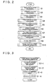
- FIG. 2 is a main flowchart showing an operation of a road shape estimation processing unit in the embodiment of the present invention.
- numeral 14 denotes an information terminal, for example, a navigation device as an on-vehicle device mounted in a vehicle, and the navigation device 14 includes a GPS sensor 15 as a current position detecting unit which detects the current position of the vehicle as a vehicle position and the direction of the vehicle as a vehicle direction, a data recording unit 16 as an information recording unit in which various information besides map data (not shown) are recorded, a navigation processing unit 17 performing various calculation processings such as navigation processing, an operation unit 34 as a first input unit with which a driver who is an operator performs a predetermined input by operating it, a display unit 35 as a first output unit for performing various types of display with images displayed on a screen (not shown) for informing the driver, an audio input unit 36 as a second input portion with which the driver performs a predetermined input by voice, an audio output unit 37 as a second output unit for performing audio output to inform the driver of various information, and a communication unit 38 as a transmission/reception unit functioning as a communication terminal
- the GPS sensor 15, data recording unit 16, operation unit 34, display unit 35, audio input unit 36, audio output unit 37 and communication unit 38 are connected to the navigation processing unit 17. Further, a vehicle speed sensor 44 or the like as a vehicle speed detecting unit which detects a vehicle speed is connected to the navigation processing unit 17.
- the GPS sensor 15 detects time besides the vehicle position and the vehicle direction. Note that it is also possible to provide a direction sensor (not shown) independently from the GPS sensor 15 for detecting the vehicle direction with the direction sensor.
- the map data include road data regarding roads connecting intersections (including branch points), node data regarding nodes representing end points (start points and end points) of the roads, intersection data regarding the intersections, search data processed for searching, facility data regarding facilities, and the like, as well as feature data regarding features on the road.
- the road data include data representing road links from start points to end points of the roads on the database, and data of shape interpolation points (hereinafter referred to as "interpolation point data”) as a plurality of set points which are set along roads for representing road shapes on the road links.
- the interpolation point data include the numbers, coordinates, and the like of the shape interpolation points. Note that each node represents a start point or end point on a road link, and hence is also a shape interpolation point.
- a database constituted of a statistical data file, a database constituted of a traveling history data file, and the like are provided.
- Statistical data are recorded in the statistical data file
- traveling history data are recorded in the traveling history data file, both as actual data.
- the data recording unit 16 includes a disk (not shown) such as a hard disk, CD, DVD or optical disk for recording the various aforementioned data, and further includes a head (not shown) such as a reading/writing head for reading or writing various data. Further, a memory card or the like can be used for the data recording unit 16.
- the navigation processing unit 17 has a CPU 31 as a control device performing overall control of the navigation device 14 and as an arithmetic unit, a RAM 32 used as a working memory when the CPU 31 performs various arithmetic processing, a ROM 33 in which various programs for performing a search of route to a destination, route guidance, and the like are recorded besides a control program, a flash memory (not shown) used for recording various data and programs, and the like.
- a keyboard (not shown), mouse, and/or the like provided independently from the display unit 35 can be used. Further, as the operation unit 34, it is possible to use a touch panel which allows to perform a predetermined input operation by touching or clicking image operation units such as various keys, switches, buttons, and the like which are displayed by images on a screen formed on the display unit 35.
- a display is used as the display unit 35, which allows to display, on/in various screens displayed on the display unit 35, the vehicle position, vehicle direction and the like, as well as a map, a searched route, guidance information along the searched route, traffic information, and so on, and to display the distance to the next intersection on the searched route and a traveling direction on the next intersection.
- the audio input unit 36 comprises a microphone (not shown) or the like, and is adapted to allow input of necessary information by voice.
- the audio output unit 37 comprises an audio synthesis device (not shown) and a speaker (not shown), and performs route guidance of the searched route by audio output.
- the communication unit 38 comprises a beacon receiver (not shown) for receiving various information such as current traffic information and general information transmitted from a vehicle information and communication system center, a FM receiver (not shown) for receiving the various information as an FM multiplex broadcast via an FM broadcast station, and so on. Further, the communication unit 38 is able to receive data such as map data, statistical data, and traveling history data besides information such as traffic information and general information via a network (not shown) from an information center (not shown).
- the navigation processing unit 17, CPU 31, and so on function as a computer independently or in combination of two or more of them, and performs arithmetic processing based on various programs, data, and the like.
- the data recording unit 16, RAM 32, ROM 33, flash memory, and so on form a storage device and a recording medium.
- an MPU or the like can be used instead of the CPU 31.
- numeral 10 denotes an automatic transmission
- numeral 11 denotes an automatic transmission control device
- numeral 51 denotes an engine control unit
- numeral 52 denotes an engine.
- the operation unit 34 is operated by the driver and the navigation device 14 is started, a current position reading processing unit (not shown) of the CPU 31 performs current position reading processing so as to read the vehicle position and the vehicle direction detected by the GPS sensor 15. Then a matching processing unit (not shown) of the CPU 31 performs matching processing and identifies the vehicle position by determining on which of the road links the vehicle is located based on the trace of the read vehicle position, and shapes, arrangements, and the like of road links forming roads in the surrounding area of the vehicle position.
- a basic information obtaining processing unit (not shown) of the CPU 31 performs basic information obtaining processing to read and obtain the map data from the data recording unit 16.
- the map data can be obtained from the information center or the like, and in this case, the basic information obtaining processing unit downloads the received map data into the flash memory.
- a display processing unit (not shown) of the CPU 31 performs display processing to form various screens on the display unit 35.
- a map display processing unit of the display processing unit performs map display processing to form a map screen on the display unit 35 so as to display a surrounding map and further display the vehicle position and the vehicle direction on the map screen.
- the driver can drive the vehicle according to the surrounding map, the vehicle position and the vehicle direction.
- a destination setting processing unit (not shown) of the CPU 31 performs destination setting processing to set the destination. Note that a place of departure can be inputted and set as necessary. Further, it is possible to register a predetermined point in advance, and set the registered point as a destination. Subsequently, when the driver inputs a search condition by operating the operation unit 34, a search condition setting processing unit (not shown) of the CPU 31 performs search condition setting processing to set the search condition.
- a route search processing unit (not shown) of the CPU 31 performs route search processing to read the vehicle position, vehicle direction, destination, search condition and the like and also read the search data and the like from the data recording unit 16, search for a route from a place of departure represented by the vehicle position to the destination with the search condition based on the vehicle position, vehicle direction, destination, search data, and the like, and output route data representing a searched route.
- the route search processing the route having a smallest sum of link costs added respectively to road links is taken as the searched route.
- the place of departure can also be a predetermined point set by the driver instead of the vehicle position, so as to search for a route from the predetermined point to the destination.
- a guidance processing unit (not shown) of the CPU 31 performs guidance processing to perform route guidance.
- a guidance display processing unit of the guidance processing unit performs guidance display processing to read the route data and display the searched route on the map screen based on the route data.
- intersection is set as a guidance intersection, i.e., as a subject of performing guidance on direction how and where to drive the vehicle.
- An audio output processing unit of the guidance processing unit performs audio output processing to perform the route guidance by audio output before the vehicle reaches the guidance intersection.
- a guidance point enlarged view formation processing unit of the guidance processing unit performs guidance point enlarged view formation processing to form, in a predetermined region of the map screen, an enlarged view of the guidance intersection, namely, an intersection enlarged view as a guidance point enlarged view before the vehicle reaches the guidance intersection, and thereby perform route guidance with the intersection enlarged view.
- the intersection enlarged view is displayed.
- a surrounding map of the guidance intersection, a searched route, and a landmark of a facility or the like to be a marker at the guidance intersection are displayed on the intersection enlarged view.
- information obtained in the navigation device 14 is transmitted to the automatic transmission control device 11 so as to change the shift speed of the automatic transmission 10 corresponding to the road shape ahead of the vehicle position, or transmitted to the engine control device 51 so as to change the output of the engine 52 corresponding to the road shape ahead of the vehicle position, thereby controlling traveling of the vehicle.
- the CPU 31 functions as a road shape estimating device, and a road shape estimation processing unit (not shown) of the CPU 31 performs road shape estimation processing so as to estimate the road shape by a method which will be described later.
- a traveling control processing unit (not shown) of the CPU 31 performs traveling control processing to transmit a signal for changing the shift speed of the automatic transmission 10 or changing the output of the engine 52 according to the estimated road shape to the automatic transmission control device 11, the engine control device 51, or the like.
- a data obtaining processing unit of the road shape estimation processing unit performs data obtaining processing to set a predetermined region ahead of the vehicle position including the road to be a target of estimating a road shape as a road shape estimation range, reads road data from the data recording unit 16, and obtains node data within the road shape estimation range.
- each road link for which estimation of a road shape is performed in a road on the database is referred to as a shape estimation road.
- the data obtaining processing unit obtains interpolation point data of shape interpolation points on the shape estimation road ahead of the vehicle position. Note that in this embodiment, the data obtaining processing unit obtains the node data and the interpolation point data by reading them from the data recording unit 16, but they can be obtained also by receiving via a network from the information center or the like.
- a radius calculation processing unit of the road shape estimation processing unit performs radius calculation processing to calculate a radius (radius of curvature) in each shape interpolation point of the shape estimation road by three-point calculation method based on the interpolation point data of shape interpolation points on the shape estimation road ahead of the vehicle position.
- a corner detection processing unit of the road shape estimation processing unit performs corner detection processing to detect a corner in the shape estimation road on the database based on the radius, and sets a shape interpolation point where the corner starts as a candidate start point, and a shape interpolation point where the corner ends on the database as a candidate end point.
- a corner connection processing unit of the road shape estimation processing unit When a corner that should be regarded as one corner on the actual road is detected as a plurality of corners depending on the way of setting the shape interpolation points on the database, a corner connection processing unit of the road shape estimation processing unit then performs corner connection processing so as to connect the detected corners.
- first and second corner dividing processing units of the road shape estimation processing unit perform first and second corner dividing processing to divide the detected corner.
- the detected corner is divided when a predetermined shape interpolation point in the corner has a radius that is equal to or larger than a threshold (also referred as a radii threshold) for first dividing condition determination, which will be described later, and in the second corner dividing processing, the detected corner is divided when a segment between predetermined shape interpolation points in the corner has a length that is equal to or longer than a threshold for second dividing condition determination, which will be described later.
- a threshold also referred as a radii threshold
- a minimum radius calculation processing unit of the road shape estimation processing unit performs minimum radius calculation processing to calculate an appropriate minimum radius for estimating a clothoid coefficient for each corner.
- a clothoid coefficient estimation processing unit of the road shape estimation processing unit performs clothoid coefficient estimation processing to estimate a clothoid coefficient based on the minimum radius.
- a clothoid curve calculation processing unit of the road shape estimation processing unit performs clothoid curve calculation processing to form an approximate equation of the corner based on the clothoid coefficient and calculate a clothoid curve.
- a fitting processing unit of the road shape estimation processing unit performs fitting processing to correct the candidate start point and the candidate end point by matching the clothoid curve with the respective shape interpolation points on the corner, and thereby set the start point and the end point of the corner to positions approximating to a point where the corner starts and a point where the corner ends on the actual road.
- a start point/end point recording processing unit of the road shape estimation processing unit performs start point/end point recording processing to record the start point and the end point as data representing the road shape in the data recording unit 16. In this manner, the road shape is estimated.
- step S 1 the radius calculation processing is performed.
- step S2 the corner detection processing is performed.
- step S3 the corner connection processing is performed.
- step S4 the first corner dividing processing is performed.
- step S5 the second corner dividing processing is performed.
- step S6 the minimum radius calculation processing is performed.
- step S7 the clothoid coefficient estimation processing is performed.
- step S8 the clothoid curve calculation processing is performed.
- step S9 the fitting processing is performed.
- step S10 the start point/end point recording processing is performed, and the processing is finished.
- FIG. 3 is a flowchart showing the subroutine of the radius calculation processing in the embodiment of the present invention
- FIG. 4 is a diagram explaining the principle of calculating a radius in the embodiment of the present invention.
- a shape interpolation point to be a target of radius calculation processing is designated as target point ma
- a shape interpolation point that is located immediately preceding the target point ma (on the vehicle position side) is designated as preceding adjacent point mb
- a shape interpolation point that is located immediately succeeding the target point ma (on the side to depart from the vehicle position) is designated as succeeding adjacent point mc.
- the segment length of a segment on a side nearer than the target point ma (hereinafter referred to as "front side segment") that connects the target point ma and the preceding adjacent point mb is designated as L1
- the segment length of a segment on a side farther than the target point ma (hereinafter referred to as "rear side segment") that connects the target point ma and the succeeding adjacent point mc is designated as L2.
- the circle passing through the target point ma the preceding adjacent point mb and the succeeding adjacent point mc is designated as Cr
- the center of the circle Cr is designated as Q
- the radius of the circle Cr is designated as R.
- the angle which the rear side segment forms with respect to the front side segment is designated as direction angle ⁇ .
- a direction to connect the target point ma and the succeeding adjacent point mc is x-axis direction and a direction at a right angle with respect to the x axis direction is y-axis direction
- X the distance between the target point ma and the preceding adjacent point mb in the x-axis direction
- G the distance between the preceding adjacent point mb and the center Q in the x-axis direction
- H the distance between the preceding adjacent point mb and the center Q in the y-axis direction
- F the distance between the target point ma and the center Q on the y-axis direction
- the radius calculation processing unit reads the interpolation point data, calculates the segment lengths L1, L2 based on respective coordinates of the target point ma, the preceding adjacent point mb and the succeeding adjacent point mc, and calculates the direction angle ⁇ .
- the radius calculation processing unit calculates the radius R of the circle Cr by aforementioned equation (6) based on the segment lengths L1, L2 and the direction angle ⁇ . In this manner, the radius R at the target point ma can be calculated on the shape estimation road.
- step S1-1 the segment length L1 of the front side segment is calculated.
- step S1-2 the segment length L2 of the rear side segment is calculated.
- step S1-3 the direction angle ⁇ is calculated.
- step S1-4 the radius R is calculated and the process returns to the main routine.
- the direction angle ⁇ and the radius R are calculated based on calculations by the radius calculation processing unit, but it is also possible to record a direction angle ⁇ and a radius R which are calculated in advance in the database of the data recording unit 16 as part of the road data, and perform calculation by reading them from the data recording unit 16.
- step S2 of FIG. 2 Next, the corner detection processing in step S2 of FIG. 2 will be explained.
- FIG. 5 is a first explanatory diagram of the corner detection processing in the embodiment of the present invention.
- FIG. 6 is a second explanatory diagram of the corner detection processing in the embodiment of the present invention.
- FIG. 7 is a third explanatory diagram of the corner detection processing in the embodiment of the present invention.
- FIG. 8 is a fourth explanatory diagram of the corner detection processing in the embodiment of the present invention.
- FIG. 9 is a fifth explanatory diagram of the corner detection processing in the embodiment of the present invention.
- FIG. 10 is a sixth explanatory diagram of the corner detection processing in the embodiment of the present invention.
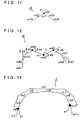
- FIG. 11 is a seventh explanatory diagram of the corner detection processing in the embodiment of the present invention.
- FIG. 12 is an eighth explanatory diagram of the corner detection processing in the embodiment of the present invention.
- FIG. 13 is a ninth explanatory diagram of the corner detection processing in the embodiment of the present invention.
- the direction angle ⁇ i is an angle which the rear side segment forms with respect to the front side segment.
- the direction angle ⁇ i takes a positive value.
- the direction angle ⁇ i takes a negative value.
- the shape interpolation points m3 to m9 are close to a straight line, and they are determined to have radii Ri that are equal to or lower than the threshold Rth and extracted.
- the candidate start point/candidate end point setting processing unit determines whether or not there are a plurality of consecutive shape interpolation points (hereinafter referred to as a "consecutive shape interpolation point group") among the extracted shape interpolation points.
- the unit takes the shape interpolation point on the nearest side (vehicle position side) in the consecutive shape interpolation point group as a candidate start point.
- the consecutive shape interpolation point group is formed by the shape interpolation points m3 to m9, and the shape interpolation point m3 is taken as the candidate start point s1.
- the candidate start point/candidate end point setting processing unit reads the direction angles ⁇ calculated by the radius calculation processing unit for the extracted shape interpolation points sequentially from the near side, and determines whether or not the positiveness or negativeness of the direction angle reverses at a predetermined shape interpolation point (the direction of the direction angle reverses with respect to the immediately preceding shape interpolation point).
- the unit determines whether or not the positiveness or negativeness reverses at the immediately succeeding shape interpolation point.
- the predetermined shape interpolation point is taken as the candidate start point.
- shape interpolation points m11 to m16 are set on a shape estimation road r2 having a shape as shown in FIG. 7 , direction angles ⁇ 12 and ⁇ 13 take negative values and direction angles ⁇ 14 and ⁇ 15 take positive values at the shape interpolation points m12 to m15.
- the positiveness or negativeness of the direction angle ⁇ 14 reverses from negative to positive at the shape interpolation point m14, and the positiveness or negativeness of the direction angle ⁇ 15 remains positive and does not reverse at the immediately succeeding shape interpolation point m15.
- the shape interpolation point m14 is taken as the candidate start point s1.
- the candidate start point/candidate end point setting processing unit determines whether or not there is a consecutive shape interpolation point group among the extracted shape interpolation points.
- the unit takes the shape interpolation point on the farthest side (side to depart from the vehicle position) in the consecutive shape interpolation point group as a candidate end point.
- the consecutive shape interpolation point group is formed by the shape interpolation points m3 to m9, and the shape interpolation point m9 is taken as the candidate end point e1.
- the candidate start point/candidate end point setting processing unit determines whether the positiveness or negativeness of the direction angle reverses at a predetermined shape interpolation point. When the positiveness or negativeness of the direction angle does not reverse at the predetermined shape interpolation point, the unit determines whether or not the positiveness or negativeness reverses at the immediately succeeding shape interpolation point. Then, when the positiveness or negativeness of the direction angle does not reverse at the predetermined shape interpolation point and the positiveness or negativeness reverses at the immediately succeeding shape interpolation point, the predetermined shape interpolation point is taken as a candidate end point.
- shape interpolation points m21 to m26 are set on a shape estimation road r3 having a shape as shown in FIG.
- direction angles ⁇ 22 and ⁇ 23 take positive values and direction angles ⁇ 24 and ⁇ 25 take negative values at the shape interpolation points m22 to m25. That is, the positiveness or negativeness of the direction angle ⁇ 23 remains positive and does not reverse at the shape interpolation point m23, and the positiveness or negativeness of the direction angle ⁇ 24 reverses from positive to negative at the immediately succeeding shape interpolation point m24. Thus, the shape interpolation point m23 is taken as a candidate end point e1.
- a corner setting processing unit of the corner detection processing unit performs cornner setting processing, and sets a corner between the candidate start point and the candidate end point.
- a shape estimation road r4 having a shape as shown in FIG. 10 a shape interpolation point m2 out of shape interpolation points m1 to m10 is taken as the candidate start point s1
- the shape interpolation point m9 is taken as the candidate end point e1
- a corner cn1 between the candidate start point s1 and the candidate end point e1 is set.
- the candidate start point/candidate end point setting processing unit sets the predetermined shape interpolation point as a single point combining a candidate start point and a candidate end point
- the corner setting processing unit sets a corner to the predetermined shape interpolation point.
- the candidate start point/candidate end point setting processing unit sets the predetermined shape interpolation point as a single point.
- direction angles ⁇ 42 to ⁇ 44, ⁇ 46 and ⁇ 47 at shape interpolation points m42 to m44, m46 and m47 among shape interpolation points m41 to m48 take positive values, and a direction angle ⁇ 45 at a shape interpolation point m45 takes a negative value.
- the positiveness or negativeness of the direction angle ⁇ 45 reverses from positive to negative at the shape interpolation point m45
- the positiveness or negativeness of the direction angle ⁇ 46 reverses from negative to positive at the immediately succeeding shape interpolation point m46.
- the shape interpolation point m45 is set to a single point f1 and a corner cn1 is set to the shape interpolation point m45.
- the corner setting processing unit sets three corners cn1 to cn3 before and after the single point f1 and at the single point f1. Note that, in this case, the numbers of the corners are added sequentially from the near side, and the number of a candidate start point and the number of a candidate end point are added corresponding to the numbers of the corners.
- the recording processing unit of the corner detection processing unit performs recording processing to record the number of corners in the shape estimation road, the number of a candidate start point, the number of a candidate end point, and so on in the RAM 32 ( FIG. 1 ).
- a shape interpolation point m6 which should be set normally on a straight line connecting shape interpolation points m5, m7, is set deviating from the straight line connecting the shape interpolation points m5, m7 between the shape interpolation points m5, m7 that is a straight section.
- radii R2 to R10 at shape interpolation points m2 to m10 calculated in the radius calculation processing are equal to or smaller than the threshold Rth and the positiveness or negativeness of direction angles do not reverse at the shape interpolation points m2 to m10.
- the corner detection processing one corner cn1 is detected in the shape interpolation points m2 to m10.
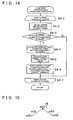
- FIG. 14 is a flowchart showing the subroutine of the first corner dividing processing in the embodiment of the present invention.
- FIG. 15 is a first explanatory diagram of the first corner dividing processing in the embodiment of the present invention.
- FIG. 16 is a second explanatory diagram of the first corner dividing processing in the embodiment of the present invention.
- FIG 17 is a third explanatory diagram of the first corner dividing processing in the embodiment of the present invention.
- FIG. 18 is a fourth explanatory diagram of the first corner dividing processing in the embodiment of the present invention.
- a corner information obtaining processing unit (radius basis corner information obtaining processing unit) of the first corner dividing processing unit performs corner information obtaining processing to obtain corner information of predetermined corners in a shape estimation road by reading it from the RAM 32.
- corner information obtaining processing unit radius basis corner information obtaining processing unit
- respective corners existing on the shape estimation road are selected in sequence as predetermined corners.
- the corner information includes the numbers of a candidate start point and a candidate end point of each corner recorded in the RAM 32 besides the interpolation point data.
- the first corner dividing processing for the shape estimation road r7 of FIG. 13 is performed.
- the corner information obtaining processing unit obtains the number of a corner cn1, the number of a candidate start point s1 of the corner cn1, the number of a candidate end point e1 of the corner cn1, the respective numbers of shape interpolation points m2 to m10, radii R2 to R10 at the respective shape interpolation points m2 to m10, and so on.
- a dividing condition determination processing unit (radius basis dividing condition determination processing unit) of the first corner dividing processing unit performs dividing condition determination processing to read the numbers of the shape interpolation points, calculate the number of shape interpolation points in a corner, and determine whether or not a first dividing condition for performing a first corner dividing processing is met by whether the number of shape interpolation points is equal to or larger than a threshold, which is three in this embodiment.
- a threshold which is three in this embodiment.
- the number of shape interpolation points m2 to m10 in the corner cn1 is nine, and thus the first dividing condition is met.
- a shape interpolation point m53 among shape interpolation points m51 to m55 has a radius equal to or smaller than the threshold and a corner is detected. However, the number of shape interpolation point m53 in the corner is one. Since three or more shape interpolation points are not included in the corner, the first dividing condition is not met.
- shape interpolation points m63, m64 among shape interpolation points m61 to m66 have radii equal to or smaller than the threshold and a corner is detected, but the number of shape interpolation points m63, m64 in the corner is two. Since three or more shape interpolation points are not included in the corner, the first dividing condition is not met.
- the dividing condition determination processing unit determines whether a radius at a predetermined shape interpolation point in the corner is relatively larger as compared to respective radii at other shape interpolation points in the corner. For this purpose, the dividing condition determination processing unit reads radii at respective shape interpolation points in the corner, and determines whether a second dividing condition is met or not by whether the predetermined shape interpolation point in the corner has a radius equal to or larger than a threshold for a first dividing condition determination calculated based on the radii at respective shape interpolation points in the corner, that is, first dividing threshold Rthcn.
- the standard deviation ⁇ 1 is an added value set corresponding to the average value Ra.
- a division execution processing unit (radius basis division execution processing unit) of the dividing condition determination processing unit performs division execution processing to divide the corner at a shape interpolation point having a radius equal to or larger than the first dividing threshold Rthcn. Specifically, the division execution processing unit adds the shape interpolation point immediately preceding the shape interpolation point having a radius equal to or larger than the first dividing threshold Rthcn as a candidate end point, and adds the shape interpolation point immediately succeeding the shape interpolation point having a radius equal to or larger than the first dividing threshold Rthcn as a candidate start point.
- the division execution processing unit adds the shape interpolation point immediately preceding the shape interpolation point having a radius equal to or larger than the first dividing threshold Rthcn as a candidate end point, and adds the shape interpolation point immediately succeeding the shape interpolation point having a radius equal to or larger than the first dividing threshold Rthcn as a candidate start point.
- the corner is divided at a shape interpolation point m6 having a radius equal to or larger than the first dividing threshold Rthcn.
- a shape interpolation point m2 is taken as a candidate start point s1
- the shape interpolation point m5 immediately preceding a shape interpolation point m6 is taken as a candidate end point e1.
- the shape interpolation point m7 immediately succeeding the shape interpolation point m6 is taken as a candidate start point s2, and a shape interpolation point m 10 is taken as a candidate end point e2.
- a corner cn1 is set by the shape interpolation points m2 to m5 and a corner cn2 is set by the shape interpolation points m7 to in m10.
- the corner division execution processing unit does not divide the current corner.
- the first dividing threshold Rthcn is calculated by adding the standard deviation ⁇ 1 to the average value Ra, it is set larger as the average value Ra gets larger or set smaller as the average value Ra gets smaller. Thus, even if noise is added to values of the respective radii R2 to R10 or the like, it is possible to precisely determine whether the second dividing condition is met or not.
- the standard deviation ⁇ 1 represents the degree of dispersion of the radii R2 to R10 at the respective shape interpolation points m2 to m10 of the corner
- easiness for dividing of the corner to be performed can be changed according to the degree of dispersion of the radii R2 to R10.
- the degree of dispersion of the radii R2 to R10 is high, the first dividing threshold Rthcn becomes large, which makes it difficult for the second dividing condition to be met, and makes it difficult for dividing of the corner to be performed.
- the first dividing threshold Rthcn becomes small, which makes it easy for the second dividing condition to be met, and makes it easy for dividing of the corner to be performed.
- the first dividing threshold Rthcn is calculated by adding the standard deviation ⁇ 1 to the average value Ra, but a first dividing threshold Rthcn that is set in advance corresponding to the average value Ra can be recorded, for example, in the data recording unit 16.
- a radius threshold map as a first threshold map in which the average value Ra and the first dividing threshold Rthcn correspond to each other is recorded in the ROM 33.
- the division execution processing unit refers to the radius threshold map to read the first dividing threshold Rthcn corresponding to the average value Ra, compares each of R2 to R10 with the first dividing threshold Rthcn, and divides the corner at a shape interpolation point having a radius equal to or larger than the first dividing threshold Rthcn.
- step S4-1 a loop by the number of corners is started.
- step S4-2 corner information of the current corner is obtained.
- step S4-3 it is determined whether the number of shape interpolation points in the corner is three or more. When the number of shape interpolation points in the corner is three or more, the process proceeds to step S4-4. When the number of shape interpolation points in the corner is smaller than three, the process proceeds to step S4-7.
- step S4-4 the average value of radii of the shape interpolation points in the corner is calculated.
- step S4-5 the first dividing threshold Rthcn is calculated from the average value Ra.
- step S4-6 the corner is divided at a shape interpolation point having a radius equal to or larger than the first dividing threshold Rthcn.
- step S4-7 the loop by the number of corners is finished, and the process is finished.
- FIG. 19 is a tenth explanatory diagram of the corner detection processing in the embodiment of the present invention.
- a shape interpolation point that should be set is not set in the section between shape interpolation points m5, m6, which is a straight section.
- radii R2 to R9 at shape interpolation points m2 to m9 calculated in the radius calculation processing are equal to or lower than the threshold Rth, and the positiveness or negativeness of direction angles do not reverse at the shape interpolation points m2 to m9.
- the corner detection processing one corner cn1 is detected for the shape interpolation points m2 to m9.
- dividing of the corner is performed by the second corner dividing processing unit.
- FIG. 20 is a flowchart showing the subroutine of the second corner dividing processing in the embodiment of the present invention.
- FIG. 21 is a first explanatory diagram of the second corner dividing processing in the embodiment of the present invention.
- FIG. 22 is a second explanatory diagram of the second corner dividing processing in the embodiment of the present invention.
- FIG. 23 is a third explanatory diagram of the second corner dividing processing in the embodiment of the present invention.
- a corner information obtaining processing unit (segment length basis corner information obtaining processing unit) of the second corner dividing processing unit performs corner information obtaining processing to obtain corner information of predetermined corners in a shape estimation road by reading it from the RAM 32.
- respective corners existing on the shape estimation road are selected in sequence as predetermined corners.
- the corner information includes the numbers of a candidate start point and a candidate end point of each corner recorded in the RAM 32 besides the interpolation point data.
- the second corner dividing processing for a shape estimation road r10 is performed.
- the corner information obtaining processing unit obtains the number of a corner cn1, the number of a candidate start point s1 of the corner cn1, the number of a candidate end point e1 of the corner cn1, the respective numbers of shape interpolation points m2 to m9, segment lengths of respective segments between the respective shape interpolation points m2 to m9, and so on.
- a dividing condition determination processing unit (segment length basis dividing condition determination processing unit) of the second corner dividing processing unit performs dividing condition determination processing to read the numbers of the shape interpolation points, calculate the number of shape interpolation points in a corner, and determine whether or not a first dividing condition for performing a second corner dividing processing is met by whether the number of shape interpolation points is equal to or larger than a threshold, which is three in this embodiment.
- a threshold which is three in this embodiment.
- the number of shape interpolation points m2 to m9 in the corner cn1 is eight, and thus the first dividing condition is met.
- the first dividing condition is not met.
- the dividing condition determination processing unit determines whether a segment length between predetermined shape interpolation points in the corner is relatively longer as compared to respective segment lengths between other shape interpolation points in the corner. For this purpose, the dividing condition determination processing unit reads the segment lengths between respective shape interpolation points in the corner, and determines whether a second dividing condition is met or not by whether segments between predetermined shape interpolation points in the corner have segment lengths equal to or larger than a threshold for a second dividing condition determination calculated based on the segment lengths between respective shape interpolation points in the corner, that is, a second dividing threshold Lthcn.
- the division execution processing unit (segment length basis division execution processing unit) of the dividing condition determination processing unit performs division execution processing to divide the corner by a segment having a segment length equal to or larger than the second dividing threshold Lthcn. Further, the division execution processing unit takes the preceding shape interpolation point out of the shape interpolation points forming the segment having a segment length equal to or larger than the second dividing threshold Lthcn as a candidate end point, and takes the succeeding shape interpolation point out of the shape interpolation points forming the segment having a segment length equal to or larger than the second dividing threshold Lthcn as a candidate start point.
- the division execution processing unit takes the preceding shape interpolation point out of the shape interpolation points forming the segment having a segment length equal to or larger than the second dividing threshold Lthcn as a candidate end point, and takes the succeeding shape interpolation point out of the shape interpolation points forming the segment having a segment length equal to or larger than the second dividing threshold Lthc
- the corner cn1 is divided by the segment between the shape interpolation points m5, m6 having a segment length Lc11 that is equal to or larger than the second dividing threshold Lthcn.
- a shape interpolation point m2 is taken as a candidate start point s1
- the shape interpolation point m5 preceding the segment between the shape interpolation points m5, m6 is taken as a candidate end point e1
- the shape interpolation point m6 succeeding the segment between the shape interpolation points m5, m6 is taken as a candidate start point s2
- a shape interpolation point m9 is taken as a candidate end point e2.
- a corner cn1 is formed by the shape interpolation points m2 to m5
- a corner cn2 is formed by the shape interpolation points m6 to m9.
- the corner division execution processing unit does not divide the current corner.
- the second dividing threshold Lthcn is calculated by adding the standard deviation ⁇ 2 to the average value La, and it is set larger as the average value La gets larger or set smaller as the average value La gets smaller.
- the standard deviation ⁇ 2 represents the degree of dispersion of the respective segment lengths between the respective shape interpolation points m2 to m9 of the corner
- easiness for dividing of the corner to be performed can be changed according to the degree of dispersion of the segment lengths.
- the degree of dispersion of the segment lengths is high, the second dividing threshold Lthcn becomes large, which makes it difficult for the second dividing condition to be met, and makes it difficult for the corner to be divided.
- the degree of dispersion of the segment lengths is low, the second dividing threshold Lthcn becomes small, which makes it easy for the second dividing condition to be met, and makes it easy for the corner to be divided.
- the second dividing threshold Lthcn is calculated by adding the standard deviation ⁇ 2 to the average value La, but a second dividing threshold Lthcn that is set in advance corresponding to the average value La can be recorded, for example, in the data recording unit 16.
- a segment length threshold map as a second threshold map in which the average value La and the second dividing threshold Lthcn correspond to each other is recorded in the ROM 33.
- the division execution processing unit refers to the segment length threshold map to read the second dividing threshold Lthcn corresponding to the average value La, compares the segment lengths between the respective shape interpolation points m2 to m9 with the second dividing threshold Lthcn, and divides the corner by a segment having a segment length equal to or larger than the second dividing threshold Lthcn.
- step S5-1 a loop by the number of corners is started.
- step S5-2 corner information of the current corner is obtained.
- step S5-3 it is determined whether the number of shape interpolation points in the corner is three or more. When the number of shape interpolation points in the corner is three or more, the process proceeds to step S5-4. When the number of shape interpolation points in the corner is smaller than three, the process proceeds to step S5-7.
- step S5-4 the average value La of segment lengths in the corner is calculated.
- step S5-5 the second dividing threshold Lthcn is calculated from the average value La.
- step S5-6 the corner is divided by a segment having a segment length equal to or larger than the second dividing threshold Lthcn.
- step S5-7 the loop by the number of corners is finished, and the process is finished.
- FIG. 24 is a table showing a clothoid coefficient map in the embodiment of the present invention.
- minimum radii Rmin and square values A 2 of the clothoid coefficient A of a clothoid curve are recorded corresponding to each other as a clothoid coefficient map in the ROM 33 ( FIG. 1 ), and the clothoid coefficient estimation processing unit reads the minimum radius Rmin calculated in aforementioned step S6, refers to the clothoid coefficient map, and reads the value A 2 corresponding to the minimum radius Rmin. Subsequently, the clothoid coefficient estimation processing unit calculates and estimates a clothoid coefficient A. Note that the clothoid coefficient map is created based on a relationship between a radius on the actual road and the clothoid coefficient of a clothoid curve that is used when designing this road.
- FIG. 25 is a flowchart showing the subroutine of the clothoid curve calculation processing in the embodiment of the present invention.
- the clothoid curve is a curve having a radius of curvature that becomes smaller with distance from its origin.
- a part of the clothoid curve is assigned to the start point or end point of a corner.
- a curve radius at the point S is Rc
- L ⁇ Rc A 2 ... (7)
- the X coordinate and Y coordinate of the clothoid curve can be calculated by polynomials shown by equations (8) and (9), respectively.
- the clothoid curve is calculated based on the clothoid coefficient A calculated in the clothoid coefficient estimation processing by the clothoid curve calculation processing unit.
- the clothoid curve calculation processing unit approximates and calculates the X coordinate and the Y coordinate of the clothoid curve (point S of the curve length L (k)) by equations (10) and (11) obtained based on simulation.
- X 0 and Y 0 are X coordinate and Y coordinate of a start point of the clothoid curve. Further, angle ⁇ is expressed by equation (12).
- ⁇ ⁇ + 2k ⁇ L ... (12)
- ⁇ is the direction of the start point of the clothoid curve
- value k is expressed by the following equation (13).
- step S8-1 a loop is started by the curve length L(k) of the clothoid curve.
- step S8-2 the X coordinate of the point S of the curve length L(k) is calculated.
- step S8-3 the Y coordinate of the point S of the curve length L(k) is calculated.
- step S8-4 the loop is finished by the curve length L(k) of the clothoid curve, and the process returns to the main routine.
- FIG. 26 is an explanatory diagram of the fitting processing in the embodiment of the present invention.
- reference numeral r7 denotes a shape estimation road
- reference numeral cn1 denotes a corner set by the corner connection processing and the first, second corner dividing processing
- reference numerals m1 to m5 denote shape interpolation points forming the corner cn1
- reference numeral s1 denotes a candidate start point of the corner cn1.
- a clothoid curve movement processing unit of the fitting processing unit performs clothoid curve movement processing to place the origin Qs of a clothoid curve Q on an extended line of the segment Sg1 connecting the shape interpolation points m1, m2, and move the clothoid curve Q in an arrow E direction so that a tangent line on the origin Qs and the extended line of the segment Sg1 correspond.
- an error calculation processing unit of the fitting processing unit performs error calculation processing to calculate the sum of errors of the position of the clothoid curve Q with respect to the respective shape interpolation points m2 to m5 after the shape interpolation point m2.
- the errors of the position of the clothoid curve Q with respect to the respective shape interpolation points m2 to m5 are calculated based on a distance on the X-axis and a distance on the Y-axis between the shape interpolation points m2 to m5 and each point plotted when drawing the clothoid curve Q.
- the clothoid curve movement processing unit matches the clothoid curve Q with the shape interpolation points m2 to m5 so that the sum of the errors becomes smallest, so as to set the position of the clothoid curve Q.
- a start point/end point extraction processing unit of the fitting processing unit performs start point/end point extraction processing, and set the origin Qs of the clothoid curve Q as a start point Sal of the actual corner when the position of the clothoid curve Q is set.
- the clothoid curve movement processing unit, the error calculation processing unit and the start point/end point extraction processing unit perform similar processing on the end point side of the corner cn1 so as to set the position of the clothoid curve Q, and then set the origin of the clothoid curve Q as an end point of the actual corner.
- the candidate start point and the candidate end point are corrected with the clothoid curve Q, and the collected candidate start point and candidate end point can be set as the start point and end point of the actual corner, respectively.
- the candidate start point and the candidate end point of the corner cn1 can be made close to the start point and the end point of a corner on the actual road.
- step S10 of FIG. 2 Next, the start point/end point recording processing in step S10 of FIG. 2 will be explained.
- the start point/end point recording processing unit records positions of extracted candidate start point and candidate end point as data representing the road shape in the data recording unit 16.
- a road shape can be estimated precisely, and the start point and the end point of an actual corner are set based on the precisely estimated road shape. Therefore, it is possible to precisely control traveling of the vehicle by changing the shift speed of the automatic transmission 10 corresponding to the road shape or changing the output of the engine 52 corresponding to the road shape.
- estimation of a road shape is performed by operation of the CPU 31 of the navigation device 14, but it is possible to estimate a road shape by operation of a CPU (not shown) of the automatic transmission control device 11 or by operation of a CPU as a control device of the information center.
- a vehicle control device is disposed as a control device at a higher level than the automatic transmission control device 11 and the engine control device 51 so as to perform overall control of the entire vehicle, and it is also possible to estimate a road shape by operation of a CPU of this vehicle control device.
- estimation of road shape is performed for a shape estimation road between adjacent nodes, but when a road shape is estimated for every shape estimation road between respective nodes in the case where there is a node in a corner on the actual road, the processing becomes different before and after the node in the corner.
- road following data are added between respective road links in road data, and when a road link that is expected to be entered after passing the node is clear, or when a searched route is set by route search processing, estimation of road shape can be performed for two or more consecutive shape estimation roads.
Landscapes
- Engineering & Computer Science (AREA)
- Radar, Positioning & Navigation (AREA)
- Remote Sensing (AREA)
- Automation & Control Theory (AREA)
- Physics & Mathematics (AREA)
- General Physics & Mathematics (AREA)
- Mechanical Engineering (AREA)
- Chemical & Material Sciences (AREA)
- Transportation (AREA)
- Combustion & Propulsion (AREA)
- Mathematical Physics (AREA)
- Traffic Control Systems (AREA)
- Navigation (AREA)
- Image Analysis (AREA)
Claims (9)
- Straßenformabschätzvorrichtung, mit:einer Datengewinnungsverarbeitungseinheit (31), die dazu angepasst ist, Interpolationspunktdaten einer Mehrzahl von Forminterpolationspunkten (mi), die entlang einer Straße (r1-r10) festgelegt sind und eine Form der Straße wiedergeben, zu gewinnen;einer Radiusberechnungsverarbeitungseinheit (31), die dazu angepasst ist, einen Radius (R) einer Krümmung an jedem der Forminterpolationspunkte (mi) basierend auf den Interpolationspunktdaten in einem vorbestimmten Abschnitt der Straße zu berechnen; undeiner Eckendetektionsverarbeitungseinheit (31), die dazu angepasst ist, eine Ecke (cn1) in dem vorbestimmten Abschnitt basierend auf dem Radius (R) einer Krümmung an jedem der Forminterpolationspunkte (mi) zu detektieren;dadurch gekennzeichnet, dass sie weiter aufweist:eine Eckenaufteilungsverarbeitungseinheit (31), die dazu angepasst ist, einen Radiengrenzwert entsprechend einem Durchschnittswert von Radien einer Krümmung an jeweiligen Forminterpolationspunkten (mi) in der detektierten Ecke (cn1) festzulegen, und dazu angepasst ist, ein Aufteilen der Ecke (cn1) an einem Forminterpolationspunkt (m6), der einen Radius (R) einer Krümmung gleich zu oder größer als der Radiengrenzwert in der detektierten Ecke aufweist, auszuführen; wobeidie Straßenform separat für jede der aufgeteilten Ecken abgeschätzt wird.
- Straßenformabschätzvorrichtung nach Anspruch 1, bei der:die Eckenaufteilungsverarbeitungseinheit (31) weiter dazu angepasst ist, Segmentlängen (Lc11) von Segmenten zwischen jeweiligen Forminterpolationspunkten (m5, m6) in der detektierten Ecke (cn1) zu gewinnen, und dazu angepasst ist, ein Aufteilen der Ecke (cn1) durch ein Segment, das eine Segmentlänge (Lc11) gleich zu oder größer als ein Segmentlängengrenzwert, der entsprechend einem Durchschnittswert der jeweiligen Segmentlängen (Lc11) festgelegt ist, auszuführen.
- Straßenformabschätzvorrichtung nach Anspruch 1 oder 2, bei der
der Radiengrenzwert entsprechend einem Streuungsgrad von Radien (R) einer Krümmung an entsprechenden Forminterpolationspunkten (mi) in der Ecke (cn1) festgelegt wird. - Straßenformabschätzvorrichtung nach Anspruch 1, bei der
der Segmentlängengrenzwert entsprechend einem Streuungsgrad der Segmentlängen (Lc 11) festgelegt wird. - Straßenformabschätzverfahren mit den folgenden Schritten:Gewinnen von Interpolationspunktdaten einer Mehrzahl von Forminterpolationspunkten (mi), die entlang einer Straße (r1-r10) festgelegt sind und eine Form der Stra0e (r1-r10) wiedergeben;Berechnen eines Radius (R) einer Krümmung an jedem der Forminterpolationspunkte (mi) basierend auf den Interpolationspunktdaten in einem vorbestimmten Abschnitt der Straße (r1-r10); undDetektieren einer Ecke (cn1) in dem vorbestimmten Abschnitt basierend auf dem Radius (R) einer Krümmung an jedem der Forminterpolationspunkte (mi);gekennzeichnet durch die weiteren Schritte:Festlegen eines Radiengrenzwertes entsprechend einem Durchschnittswert von Radien (R) einer Krümmung an entsprechenden Forminterpolationspunkten (mi) in der detektierten Ecke (cn1); undAusführen eines Aufteilens der Ecke (cn1) an einem Forminterpolationspunkt (m6), der einen Radius (R) einer Krümmung gleich zu oder größer als der Radiengrenzwert in der detektierten Ecke (cn1) aufweist,wobei die Straßenform getrennt für jede der unterteilten Ecken abgeschätzt wird.
- Straßenformabschätzverfahren nach Anspruch 5, weiter aufweisend die Schritte:Gewinnen von Segmentlängen (Lc11) von Segmenten zwischen jeweiligen Forminterpolationspunkten (m5, m6) in der detektierten Ecke (cn1); undAusführen eines Aufteilens der Ecke (cn1) durch ein Segment, das eine Segmentlänge (Lc11) gleich zu oder größer als ein Segmentlängengrenzwert, der entsprechend einem Durchschnittswert von entsprechenden Segmentlängen (Lc11) festgelegt ist, aufweist.
- Straßenformabschätzverfahren nach Anspruch 5 oder 6, weiter aufweisend die Schritte
Festlegen des Radiengrenzwertes entsprechend einem Streuungsgrad von Radien (R) einer Krümmung an entsprechenden Forminterpolationspunkten (mi) in der Ecke (cn1). - Straßenformabschätzverfahren nach Anspruch 6, weiter aufweisend die Schritte
Festlegen des Segmentlängengrenzwertes entsprechend einem Streuungsgrad der Segmentlängen (Lc11). - Programm mit Programmcode, der, wenn er auf einem Computer ausgeführt wird, bewirkt, dass der Computer die Schritte eines Verfahrens nach einem der Ansprüche 5 bis 8 ausführt.
Applications Claiming Priority (2)
| Application Number | Priority Date | Filing Date | Title |
|---|---|---|---|
| JP2008087892A JP4479816B2 (ja) | 2008-03-28 | 2008-03-28 | 道路形状推定装置、道路形状推定方法及びプログラム |
| JP2008087902A JP4479817B2 (ja) | 2008-03-28 | 2008-03-28 | 道路形状推定装置、道路形状推定方法及びプログラム |
Publications (3)
| Publication Number | Publication Date |
|---|---|
| EP2105708A2 EP2105708A2 (de) | 2009-09-30 |
| EP2105708A3 EP2105708A3 (de) | 2011-11-30 |
| EP2105708B1 true EP2105708B1 (de) | 2013-12-04 |
Family
ID=40802008
Family Applications (1)
| Application Number | Title | Priority Date | Filing Date |
|---|---|---|---|
| EP09004261.5A Not-in-force EP2105708B1 (de) | 2008-03-28 | 2009-03-25 | Straßenformeinschätzungsvorrichtung, Straßenformeinschätzungsverfahren und Programm |
Country Status (1)
| Country | Link |
|---|---|
| EP (1) | EP2105708B1 (de) |
Families Citing this family (4)
| Publication number | Priority date | Publication date | Assignee | Title |
|---|---|---|---|---|
| EP3726184B1 (de) * | 2019-04-16 | 2025-06-11 | Stellantis Auto SAS | Verfahren und vorrichtung zur bestimmung des kurvenverlaufs einer strasse |
| DE102019112413B4 (de) * | 2019-05-13 | 2025-10-09 | Bayerische Motoren Werke Aktiengesellschaft | Verfahren und vorrichtung zur multi-sensor-datenfusion für automatisierte und autonome fahrzeuge |
| CN112762946B (zh) * | 2020-12-17 | 2023-06-27 | 武汉光庭信息技术股份有限公司 | 一种道路分段处理方法及系统 |
| CN115014367B (zh) * | 2022-06-06 | 2025-05-20 | 高德软件有限公司 | 一种道路匹配方法及装置 |
Family Cites Families (8)
| Publication number | Priority date | Publication date | Assignee | Title |
|---|---|---|---|---|
| DE19604364A1 (de) * | 1996-02-07 | 1997-08-14 | Fraunhofer Ges Forschung | Verfahren zur Ermittlung einer Straßenkrümmung aus digital abgelegten Karteninformationen |
| JP3508619B2 (ja) * | 1999-05-13 | 2004-03-22 | 株式会社デンソー | 車両用ナビゲーション装置 |
| JP3167993B2 (ja) * | 1999-09-21 | 2001-05-21 | 富士重工業株式会社 | 道路形状推定装置及びそれを用いたカーブ進入制御装置 |
| JP2001101597A (ja) * | 1999-09-30 | 2001-04-13 | Toyota Motor Corp | 道路形状認識方法、装置および記録媒体 |
| JP4576844B2 (ja) * | 2004-01-30 | 2010-11-10 | アイシン・エィ・ダブリュ株式会社 | 道路形状推測装置 |
| DE102004006687A1 (de) * | 2004-02-11 | 2005-09-01 | Daimlerchrysler Ag | Verfahren zur Beschreibung eines Weges in einer digitalisierten Karte |
| JP4506261B2 (ja) * | 2004-04-28 | 2010-07-21 | 日産自動車株式会社 | カーブ曲率推定装置及びカーブ曲率推定方法 |
| EP1593936B1 (de) * | 2004-04-30 | 2013-02-27 | Koito Manufacturing Co., Ltd | Beleuchtungssystem für ein Kraftfahrzeug |
-
2009
- 2009-03-25 EP EP09004261.5A patent/EP2105708B1/de not_active Not-in-force
Also Published As
| Publication number | Publication date |
|---|---|
| EP2105708A2 (de) | 2009-09-30 |
| EP2105708A3 (de) | 2011-11-30 |
Similar Documents
| Publication | Publication Date | Title |
|---|---|---|
| JP4475342B2 (ja) | 道路形状推定装置、道路形状推定方法及びプログラム | |
| JP4479816B2 (ja) | 道路形状推定装置、道路形状推定方法及びプログラム | |
| EP2009400B1 (de) | Vorrichtung zur Fahrzeugpositionserkennung, Navigationsvorrichtung, Verfahren zur Fahrzeugpositionserkennung | |
| JP6036371B2 (ja) | 車両用運転支援システム及び運転支援方法 | |
| US8265869B2 (en) | Vehicle navigation apparatus and vehicle navigation program | |
| JP6161942B2 (ja) | カーブ形状モデル化装置、車両情報処理システム、カーブ形状モデル化方法、及びカーブ形状モデル化プログラム | |
| CN114954527A (zh) | 一种车道级导航规划方法、装置、设备、介质及车辆 | |
| JP2009008590A (ja) | 自車位置認識装置及び自車位置認識プログラム | |
| JP2018040693A (ja) | 運転支援装置、運転支援方法 | |
| US20090248299A1 (en) | Road shape estimating device, road shape estimating method and program | |
| JP2001052300A (ja) | カーブ進入制御装置 | |
| JP4010380B2 (ja) | 車両制御装置及びプログラムを記録した記録媒体 | |
| JP4479817B2 (ja) | 道路形状推定装置、道路形状推定方法及びプログラム | |
| EP2105708B1 (de) | Straßenformeinschätzungsvorrichtung, Straßenformeinschätzungsverfahren und Programm | |
| JP4875509B2 (ja) | ナビゲーション装置及びナビゲーション方法 | |
| JP5203747B2 (ja) | ナビゲーション装置 | |
| JP5901358B2 (ja) | 車載装置 | |
| JP5504743B2 (ja) | 走行支援内容決定装置、走行支援内容決定方法および走行支援内容決定プログラム | |
| JP5565561B2 (ja) | 運転アシストシステム | |
| JP4835413B2 (ja) | 車両用ナビゲーション装置 | |
| JP2008171114A (ja) | 車両走行ライン演算装置及び方法並びにプログラム | |
| CN115187937A (zh) | 用于为车辆确定道路边界的方法和设备 | |
| JP2002148066A (ja) | 経路探索装置及び媒体 | |
| JP2006317286A (ja) | 車載ナビゲーション装置 | |
| JP4957021B2 (ja) | 車両用地図データ作成装置、及び、車両用地図データ更新装置 |
Legal Events
| Date | Code | Title | Description |
|---|---|---|---|
| PUAI | Public reference made under article 153(3) epc to a published international application that has entered the european phase |
Free format text: ORIGINAL CODE: 0009012 |
|
| AK | Designated contracting states |
Kind code of ref document: A2 Designated state(s): AT BE BG CH CY CZ DE DK EE ES FI FR GB GR HR HU IE IS IT LI LT LU LV MC MK MT NL NO PL PT RO SE SI SK TR |
|
| AX | Request for extension of the european patent |
Extension state: AL BA RS |
|
| PUAL | Search report despatched |
Free format text: ORIGINAL CODE: 0009013 |
|
| AK | Designated contracting states |
Kind code of ref document: A3 Designated state(s): AT BE BG CH CY CZ DE DK EE ES FI FR GB GR HR HU IE IS IT LI LT LU LV MC MK MT NL NO PL PT RO SE SI SK TR |
|
| AX | Request for extension of the european patent |
Extension state: AL BA RS |
|
| RIC1 | Information provided on ipc code assigned before grant |
Ipc: B60W 40/06 20060101ALI20111024BHEP Ipc: G06F 17/30 20060101ALI20111024BHEP Ipc: G01C 21/32 20060101AFI20111024BHEP |
|
| 17P | Request for examination filed |
Effective date: 20120525 |
|
| AKX | Designation fees paid |
Designated state(s): AT BE BG CH CY CZ DE DK EE ES FI FR GB GR HR HU IE IS IT LI LT LU LV MC MK MT NL NO PL PT RO SE SI SK TR |
|
| RIC1 | Information provided on ipc code assigned before grant |
Ipc: B60W 40/06 20120101ALI20130131BHEP Ipc: G01C 21/32 20060101AFI20130131BHEP Ipc: G06F 17/30 20060101ALI20130131BHEP |
|
| GRAP | Despatch of communication of intention to grant a patent |
Free format text: ORIGINAL CODE: EPIDOSNIGR1 |
|
| INTG | Intention to grant announced |
Effective date: 20130429 |
|
| GRAP | Despatch of communication of intention to grant a patent |
Free format text: ORIGINAL CODE: EPIDOSNIGR1 |
|
| GRAS | Grant fee paid |
Free format text: ORIGINAL CODE: EPIDOSNIGR3 |
|
| INTG | Intention to grant announced |
Effective date: 20131003 |
|
| GRAA | (expected) grant |
Free format text: ORIGINAL CODE: 0009210 |
|
| AK | Designated contracting states |
Kind code of ref document: B1 Designated state(s): AT BE BG CH CY CZ DE DK EE ES FI FR GB GR HR HU IE IS IT LI LT LU LV MC MK MT NL NO PL PT RO SE SI SK TR |
|
| REG | Reference to a national code |
Ref country code: GB Ref legal event code: FG4D |
|
| REG | Reference to a national code |
Ref country code: CH Ref legal event code: EP |
|
| REG | Reference to a national code |
Ref country code: IE Ref legal event code: FG4D Ref country code: AT Ref legal event code: REF Ref document number: 643704 Country of ref document: AT Kind code of ref document: T Effective date: 20140115 |
|
| REG | Reference to a national code |
Ref country code: DE Ref legal event code: R096 Ref document number: 602009020472 Country of ref document: DE Effective date: 20140130 |
|
| REG | Reference to a national code |
Ref country code: NL Ref legal event code: VDEP Effective date: 20131204 |
|
| REG | Reference to a national code |
Ref country code: AT Ref legal event code: MK05 Ref document number: 643704 Country of ref document: AT Kind code of ref document: T Effective date: 20131204 |
|
| PG25 | Lapsed in a contracting state [announced via postgrant information from national office to epo] |
Ref country code: LT Free format text: LAPSE BECAUSE OF FAILURE TO SUBMIT A TRANSLATION OF THE DESCRIPTION OR TO PAY THE FEE WITHIN THE PRESCRIBED TIME-LIMIT Effective date: 20131204 Ref country code: NO Free format text: LAPSE BECAUSE OF FAILURE TO SUBMIT A TRANSLATION OF THE DESCRIPTION OR TO PAY THE FEE WITHIN THE PRESCRIBED TIME-LIMIT Effective date: 20140304 Ref country code: SE Free format text: LAPSE BECAUSE OF FAILURE TO SUBMIT A TRANSLATION OF THE DESCRIPTION OR TO PAY THE FEE WITHIN THE PRESCRIBED TIME-LIMIT Effective date: 20131204 Ref country code: HR Free format text: LAPSE BECAUSE OF FAILURE TO SUBMIT A TRANSLATION OF THE DESCRIPTION OR TO PAY THE FEE WITHIN THE PRESCRIBED TIME-LIMIT Effective date: 20131204 Ref country code: FI Free format text: LAPSE BECAUSE OF FAILURE TO SUBMIT A TRANSLATION OF THE DESCRIPTION OR TO PAY THE FEE WITHIN THE PRESCRIBED TIME-LIMIT Effective date: 20131204 Ref country code: NL Free format text: LAPSE BECAUSE OF FAILURE TO SUBMIT A TRANSLATION OF THE DESCRIPTION OR TO PAY THE FEE WITHIN THE PRESCRIBED TIME-LIMIT Effective date: 20131204 |
|
| REG | Reference to a national code |
Ref country code: LT Ref legal event code: MG4D |
|
| PG25 | Lapsed in a contracting state [announced via postgrant information from national office to epo] |
Ref country code: AT Free format text: LAPSE BECAUSE OF FAILURE TO SUBMIT A TRANSLATION OF THE DESCRIPTION OR TO PAY THE FEE WITHIN THE PRESCRIBED TIME-LIMIT Effective date: 20131204 Ref country code: CY Free format text: LAPSE BECAUSE OF FAILURE TO SUBMIT A TRANSLATION OF THE DESCRIPTION OR TO PAY THE FEE WITHIN THE PRESCRIBED TIME-LIMIT Effective date: 20131204 Ref country code: LV Free format text: LAPSE BECAUSE OF FAILURE TO SUBMIT A TRANSLATION OF THE DESCRIPTION OR TO PAY THE FEE WITHIN THE PRESCRIBED TIME-LIMIT Effective date: 20131204 |
|
| PG25 | Lapsed in a contracting state [announced via postgrant information from national office to epo] |
Ref country code: EE Free format text: LAPSE BECAUSE OF FAILURE TO SUBMIT A TRANSLATION OF THE DESCRIPTION OR TO PAY THE FEE WITHIN THE PRESCRIBED TIME-LIMIT Effective date: 20131204 Ref country code: IS Free format text: LAPSE BECAUSE OF FAILURE TO SUBMIT A TRANSLATION OF THE DESCRIPTION OR TO PAY THE FEE WITHIN THE PRESCRIBED TIME-LIMIT Effective date: 20140404 Ref country code: BE Free format text: LAPSE BECAUSE OF FAILURE TO SUBMIT A TRANSLATION OF THE DESCRIPTION OR TO PAY THE FEE WITHIN THE PRESCRIBED TIME-LIMIT Effective date: 20131204 |
|
| PG25 | Lapsed in a contracting state [announced via postgrant information from national office to epo] |
Ref country code: ES Free format text: LAPSE BECAUSE OF FAILURE TO SUBMIT A TRANSLATION OF THE DESCRIPTION OR TO PAY THE FEE WITHIN THE PRESCRIBED TIME-LIMIT Effective date: 20131204 Ref country code: SK Free format text: LAPSE BECAUSE OF FAILURE TO SUBMIT A TRANSLATION OF THE DESCRIPTION OR TO PAY THE FEE WITHIN THE PRESCRIBED TIME-LIMIT Effective date: 20131204 Ref country code: PL Free format text: LAPSE BECAUSE OF FAILURE TO SUBMIT A TRANSLATION OF THE DESCRIPTION OR TO PAY THE FEE WITHIN THE PRESCRIBED TIME-LIMIT Effective date: 20131204 Ref country code: PT Free format text: LAPSE BECAUSE OF FAILURE TO SUBMIT A TRANSLATION OF THE DESCRIPTION OR TO PAY THE FEE WITHIN THE PRESCRIBED TIME-LIMIT Effective date: 20140404 Ref country code: RO Free format text: LAPSE BECAUSE OF FAILURE TO SUBMIT A TRANSLATION OF THE DESCRIPTION OR TO PAY THE FEE WITHIN THE PRESCRIBED TIME-LIMIT Effective date: 20131204 Ref country code: CZ Free format text: LAPSE BECAUSE OF FAILURE TO SUBMIT A TRANSLATION OF THE DESCRIPTION OR TO PAY THE FEE WITHIN THE PRESCRIBED TIME-LIMIT Effective date: 20131204 |
|
| REG | Reference to a national code |
Ref country code: DE Ref legal event code: R097 Ref document number: 602009020472 Country of ref document: DE |
|
| PLBE | No opposition filed within time limit |
Free format text: ORIGINAL CODE: 0009261 |
|
| STAA | Information on the status of an ep patent application or granted ep patent |
Free format text: STATUS: NO OPPOSITION FILED WITHIN TIME LIMIT |
|
| PG25 | Lapsed in a contracting state [announced via postgrant information from national office to epo] |
Ref country code: DK Free format text: LAPSE BECAUSE OF FAILURE TO SUBMIT A TRANSLATION OF THE DESCRIPTION OR TO PAY THE FEE WITHIN THE PRESCRIBED TIME-LIMIT Effective date: 20131204 Ref country code: LU Free format text: LAPSE BECAUSE OF FAILURE TO SUBMIT A TRANSLATION OF THE DESCRIPTION OR TO PAY THE FEE WITHIN THE PRESCRIBED TIME-LIMIT Effective date: 20140325 |
|
| REG | Reference to a national code |
Ref country code: CH Ref legal event code: PL |
|
| 26N | No opposition filed |
Effective date: 20140905 |
|
| REG | Reference to a national code |
Ref country code: DE Ref legal event code: R097 Ref document number: 602009020472 Country of ref document: DE Effective date: 20140905 |
|
| REG | Reference to a national code |
Ref country code: IE Ref legal event code: MM4A |
|
| PG25 | Lapsed in a contracting state [announced via postgrant information from national office to epo] |
Ref country code: IE Free format text: LAPSE BECAUSE OF NON-PAYMENT OF DUE FEES Effective date: 20140325 Ref country code: CH Free format text: LAPSE BECAUSE OF NON-PAYMENT OF DUE FEES Effective date: 20140331 Ref country code: LI Free format text: LAPSE BECAUSE OF NON-PAYMENT OF DUE FEES Effective date: 20140331 |
|
| PG25 | Lapsed in a contracting state [announced via postgrant information from national office to epo] |
Ref country code: SI Free format text: LAPSE BECAUSE OF FAILURE TO SUBMIT A TRANSLATION OF THE DESCRIPTION OR TO PAY THE FEE WITHIN THE PRESCRIBED TIME-LIMIT Effective date: 20131204 |
|
| REG | Reference to a national code |
Ref country code: FR Ref legal event code: PLFP Year of fee payment: 7 |
|
| PG25 | Lapsed in a contracting state [announced via postgrant information from national office to epo] |
Ref country code: IT Free format text: LAPSE BECAUSE OF FAILURE TO SUBMIT A TRANSLATION OF THE DESCRIPTION OR TO PAY THE FEE WITHIN THE PRESCRIBED TIME-LIMIT Effective date: 20131204 |
|
| PGFP | Annual fee paid to national office [announced via postgrant information from national office to epo] |
Ref country code: FR Payment date: 20150309 Year of fee payment: 7 Ref country code: GB Payment date: 20150325 Year of fee payment: 7 |
|
| PG25 | Lapsed in a contracting state [announced via postgrant information from national office to epo] |
Ref country code: MT Free format text: LAPSE BECAUSE OF FAILURE TO SUBMIT A TRANSLATION OF THE DESCRIPTION OR TO PAY THE FEE WITHIN THE PRESCRIBED TIME-LIMIT Effective date: 20131204 |
|
| PG25 | Lapsed in a contracting state [announced via postgrant information from national office to epo] |
Ref country code: MC Free format text: LAPSE BECAUSE OF FAILURE TO SUBMIT A TRANSLATION OF THE DESCRIPTION OR TO PAY THE FEE WITHIN THE PRESCRIBED TIME-LIMIT Effective date: 20131204 |
|
| PG25 | Lapsed in a contracting state [announced via postgrant information from national office to epo] |
Ref country code: BG Free format text: LAPSE BECAUSE OF FAILURE TO SUBMIT A TRANSLATION OF THE DESCRIPTION OR TO PAY THE FEE WITHIN THE PRESCRIBED TIME-LIMIT Effective date: 20131204 Ref country code: GR Free format text: LAPSE BECAUSE OF FAILURE TO SUBMIT A TRANSLATION OF THE DESCRIPTION OR TO PAY THE FEE WITHIN THE PRESCRIBED TIME-LIMIT Effective date: 20140305 |
|
| PG25 | Lapsed in a contracting state [announced via postgrant information from national office to epo] |
Ref country code: TR Free format text: LAPSE BECAUSE OF FAILURE TO SUBMIT A TRANSLATION OF THE DESCRIPTION OR TO PAY THE FEE WITHIN THE PRESCRIBED TIME-LIMIT Effective date: 20131204 Ref country code: HU Free format text: LAPSE BECAUSE OF FAILURE TO SUBMIT A TRANSLATION OF THE DESCRIPTION OR TO PAY THE FEE WITHIN THE PRESCRIBED TIME-LIMIT; INVALID AB INITIO Effective date: 20090325 |
|
| GBPC | Gb: european patent ceased through non-payment of renewal fee |
Effective date: 20160325 |
|
| REG | Reference to a national code |
Ref country code: FR Ref legal event code: ST Effective date: 20161130 |
|
| PG25 | Lapsed in a contracting state [announced via postgrant information from national office to epo] |
Ref country code: GB Free format text: LAPSE BECAUSE OF NON-PAYMENT OF DUE FEES Effective date: 20160325 Ref country code: FR Free format text: LAPSE BECAUSE OF NON-PAYMENT OF DUE FEES Effective date: 20160331 |
|
| PG25 | Lapsed in a contracting state [announced via postgrant information from national office to epo] |
Ref country code: MK Free format text: LAPSE BECAUSE OF FAILURE TO SUBMIT A TRANSLATION OF THE DESCRIPTION OR TO PAY THE FEE WITHIN THE PRESCRIBED TIME-LIMIT Effective date: 20131204 |
|
| PGFP | Annual fee paid to national office [announced via postgrant information from national office to epo] |
Ref country code: DE Payment date: 20200310 Year of fee payment: 12 |
|
| REG | Reference to a national code |
Ref country code: DE Ref legal event code: R119 Ref document number: 602009020472 Country of ref document: DE |
|
| PG25 | Lapsed in a contracting state [announced via postgrant information from national office to epo] |
Ref country code: DE Free format text: LAPSE BECAUSE OF NON-PAYMENT OF DUE FEES Effective date: 20211001 |