EP2105753B1 - Circuit de détection de tension totale de batterie assemblée - Google Patents
Circuit de détection de tension totale de batterie assemblée Download PDFInfo
- Publication number
- EP2105753B1 EP2105753B1 EP09002477.9A EP09002477A EP2105753B1 EP 2105753 B1 EP2105753 B1 EP 2105753B1 EP 09002477 A EP09002477 A EP 09002477A EP 2105753 B1 EP2105753 B1 EP 2105753B1
- Authority
- EP
- European Patent Office
- Prior art keywords
- circuit
- differential amplifier
- assembled battery
- buffer
- resistors
- Prior art date
- Legal status (The legal status is an assumption and is not a legal conclusion. Google has not performed a legal analysis and makes no representation as to the accuracy of the status listed.)
- Active
Links
Images
Classifications
-
- G—PHYSICS
- G01—MEASURING; TESTING
- G01R—MEASURING ELECTRIC VARIABLES; MEASURING MAGNETIC VARIABLES
- G01R19/00—Arrangements for measuring currents or voltages or for indicating presence or sign thereof
- G01R19/0084—Measuring voltage only
-
- B—PERFORMING OPERATIONS; TRANSPORTING
- B60—VEHICLES IN GENERAL
- B60L—PROPULSION OF ELECTRICALLY-PROPELLED VEHICLES; SUPPLYING ELECTRIC POWER FOR AUXILIARY EQUIPMENT OF ELECTRICALLY-PROPELLED VEHICLES; ELECTRODYNAMIC BRAKE SYSTEMS FOR VEHICLES IN GENERAL; MAGNETIC SUSPENSION OR LEVITATION FOR VEHICLES; MONITORING OPERATING VARIABLES OF ELECTRICALLY-PROPELLED VEHICLES; ELECTRIC SAFETY DEVICES FOR ELECTRICALLY-PROPELLED VEHICLES
- B60L3/00—Electric devices on electrically-propelled vehicles for safety purposes; Monitoring operating variables, e.g. speed, deceleration or energy consumption
- B60L3/0023—Detecting, eliminating, remedying or compensating for drive train abnormalities, e.g. failures within the drive train
- B60L3/0038—Detecting, eliminating, remedying or compensating for drive train abnormalities, e.g. failures within the drive train relating to sensors
-
- B—PERFORMING OPERATIONS; TRANSPORTING
- B60—VEHICLES IN GENERAL
- B60L—PROPULSION OF ELECTRICALLY-PROPELLED VEHICLES; SUPPLYING ELECTRIC POWER FOR AUXILIARY EQUIPMENT OF ELECTRICALLY-PROPELLED VEHICLES; ELECTRODYNAMIC BRAKE SYSTEMS FOR VEHICLES IN GENERAL; MAGNETIC SUSPENSION OR LEVITATION FOR VEHICLES; MONITORING OPERATING VARIABLES OF ELECTRICALLY-PROPELLED VEHICLES; ELECTRIC SAFETY DEVICES FOR ELECTRICALLY-PROPELLED VEHICLES
- B60L58/00—Methods or circuit arrangements for monitoring or controlling batteries or fuel cells, specially adapted for electric vehicles
- B60L58/10—Methods or circuit arrangements for monitoring or controlling batteries or fuel cells, specially adapted for electric vehicles for monitoring or controlling batteries
- B60L58/18—Methods or circuit arrangements for monitoring or controlling batteries or fuel cells, specially adapted for electric vehicles for monitoring or controlling batteries of two or more battery modules
- B60L58/21—Methods or circuit arrangements for monitoring or controlling batteries or fuel cells, specially adapted for electric vehicles for monitoring or controlling batteries of two or more battery modules having the same nominal voltage
-
- G—PHYSICS
- G01—MEASURING; TESTING
- G01R—MEASURING ELECTRIC VARIABLES; MEASURING MAGNETIC VARIABLES
- G01R31/00—Arrangements for testing electric properties; Arrangements for locating electric faults; Arrangements for electrical testing characterised by what is being tested not provided for elsewhere
- G01R31/36—Arrangements for testing, measuring or monitoring the electrical condition of accumulators or electric batteries, e.g. capacity or state of charge [SoC]
- G01R31/382—Arrangements for monitoring battery or accumulator variables, e.g. SoC
-
- B—PERFORMING OPERATIONS; TRANSPORTING
- B60—VEHICLES IN GENERAL
- B60L—PROPULSION OF ELECTRICALLY-PROPELLED VEHICLES; SUPPLYING ELECTRIC POWER FOR AUXILIARY EQUIPMENT OF ELECTRICALLY-PROPELLED VEHICLES; ELECTRODYNAMIC BRAKE SYSTEMS FOR VEHICLES IN GENERAL; MAGNETIC SUSPENSION OR LEVITATION FOR VEHICLES; MONITORING OPERATING VARIABLES OF ELECTRICALLY-PROPELLED VEHICLES; ELECTRIC SAFETY DEVICES FOR ELECTRICALLY-PROPELLED VEHICLES
- B60L2240/00—Control parameters of input or output; Target parameters
- B60L2240/40—Drive Train control parameters
- B60L2240/54—Drive Train control parameters related to batteries
- B60L2240/547—Voltage
-
- B—PERFORMING OPERATIONS; TRANSPORTING
- B60—VEHICLES IN GENERAL
- B60L—PROPULSION OF ELECTRICALLY-PROPELLED VEHICLES; SUPPLYING ELECTRIC POWER FOR AUXILIARY EQUIPMENT OF ELECTRICALLY-PROPELLED VEHICLES; ELECTRODYNAMIC BRAKE SYSTEMS FOR VEHICLES IN GENERAL; MAGNETIC SUSPENSION OR LEVITATION FOR VEHICLES; MONITORING OPERATING VARIABLES OF ELECTRICALLY-PROPELLED VEHICLES; ELECTRIC SAFETY DEVICES FOR ELECTRICALLY-PROPELLED VEHICLES
- B60L2250/00—Driver interactions
- B60L2250/16—Driver interactions by display
-
- B—PERFORMING OPERATIONS; TRANSPORTING
- B60—VEHICLES IN GENERAL
- B60L—PROPULSION OF ELECTRICALLY-PROPELLED VEHICLES; SUPPLYING ELECTRIC POWER FOR AUXILIARY EQUIPMENT OF ELECTRICALLY-PROPELLED VEHICLES; ELECTRODYNAMIC BRAKE SYSTEMS FOR VEHICLES IN GENERAL; MAGNETIC SUSPENSION OR LEVITATION FOR VEHICLES; MONITORING OPERATING VARIABLES OF ELECTRICALLY-PROPELLED VEHICLES; ELECTRIC SAFETY DEVICES FOR ELECTRICALLY-PROPELLED VEHICLES
- B60L2260/00—Operating Modes
- B60L2260/40—Control modes
- B60L2260/44—Control modes by parameter estimation
-
- Y—GENERAL TAGGING OF NEW TECHNOLOGICAL DEVELOPMENTS; GENERAL TAGGING OF CROSS-SECTIONAL TECHNOLOGIES SPANNING OVER SEVERAL SECTIONS OF THE IPC; TECHNICAL SUBJECTS COVERED BY FORMER USPC CROSS-REFERENCE ART COLLECTIONS [XRACs] AND DIGESTS
- Y02—TECHNOLOGIES OR APPLICATIONS FOR MITIGATION OR ADAPTATION AGAINST CLIMATE CHANGE
- Y02T—CLIMATE CHANGE MITIGATION TECHNOLOGIES RELATED TO TRANSPORTATION
- Y02T10/00—Road transport of goods or passengers
- Y02T10/60—Other road transportation technologies with climate change mitigation effect
- Y02T10/70—Energy storage systems for electromobility, e.g. batteries
Definitions
- the present invention relates to an assembled battery total voltage detection circuit, in particular, an assembled battery total voltage detection circuit that measures voltage divided by a divider resistor connected between a plus (+) terminal and a minus (-) terminal.
- a total voltage detection circuit with insulated input and output is conventionally used in, for example, an assembled battery for a pure electric vehicle or a hybrid electric vehicle.
- the insulation is requiredbecause a vehicle occupant otherwise may get a shock when high voltage shorts to a chassis ground of a vehicle. Therefore, in a pure electric vehicle or a hybrid electric vehicle, a main control circuit connected to the chassis ground of the vehicle and a circuit for a high voltage system are insulated from each other by high resistance.
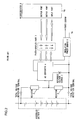
- FIG. 2 shows an example of the total voltage detection circuit for an assembled battery.
- a total voltage of an assembled battery 1 is divided to a low voltage by using resistors 2 and 3 so that the low voltage constitutes an input voltage into an A/D converter 4.
- the A/D converter 4 operates with an insulation power source 6 utilizing a reference voltage source 5 as a reference voltage.
- the A/D converter 4 is insulated via a photo-coupler portion 7.
- a microcomputer 8 performs operation control and data communication with a power source insulated from a high voltage system.
- Japanese Laid Open Patent Publication No. 2004-219414 discloses a technique in which a divider resistor constituted by a series circuit including a high resistor R1, a resistor Rm1, a resistor Rm2, and a high resistor R2 is connected between a plus terminal and a minus terminal of an assembled battery, and a voltage divided by the divider resistor is measured via a differential amplifier circuit, with a connection point (midpoint of the divider resistor) of the resistors Rm1 and Rm2 connected to a ground.
- Japanese Laid Open Patent Publication No. 2001-124805 discloses a technique for measurement through converting an assembled battery voltage to a current via a resistor and performing voltage-to-current conversion while insulating.
- the conventional assembled battery total voltage detection circuit shown in FIG. 2 has a problem that an A/D converter is required besides a main control circuit which is constituted by an insulation power source, a microcomputer, and the like, thereby resulting in an increase in production costs.
- high resistance is required to increase voltage divider ratio so as to divide voltage into one that an A/D converter can measure.
- current that flows through a total voltage detection terminal (connector) is reduced. Therefore, a costly gold-plated terminal is required so as to secure reliability of contact point of the total voltage detection terminal.
- EP-A-1898227 discloses an assembled battery total voltage detection and leak detection apparatus which performs the detection at a measurement time of a total voltage of the assembled battery by connecting an output of a positive electrode resistance voltage dividing circuit to the positive input of a differential amplifier and connecting an output of a negative electrode resistance voltage dividing circuit to the negative input of the amplifier.
- the midpoint of the resistors of the dividing circuit is connected to the ground that has the same potential as the ground terminal of the microcomputer.
- US-A-2007/0285057 discloses a leakage detection circuit for an electric vehicle, which includes a battery pack, first and second leakage detection switches, a controller, a detection resistor, a voltage detector and a calculator. The midpoint of the leakage detection resistor is also connected to the ground.
- the present invention intends to provide an assembled battery total voltage detection circuit.
- An assembled battery total voltage detection circuit is defined in claim 1.
- An example includes a main control circuit, a divider resistor connected between a plus terminal and a minus terminal of an assembled battery insulated from the main control circuit, and/or a differential amplifier circuit that amplifies voltage dividedby the divider resistor.
- a constant electric potential relative to a ground of the main control circuit is applied to a midpoint of the divider resistor, and/or the main control circuit measures the voltage divided by the divider resistor via the differential amplifier circuit.
- the differential amplifier circuit may include a buffer and a differential amplifier.
- the buffer and the differential amplifier are each constituted by an operational amplifier that operates with a single power supply.
- the assembled battery total voltage detection circuit according to the third aspect further include a buffer constituted by an operational amplifier that operates with a single power supply.
- a positive constant electric potential is applied to the midpoint of the divider resistor with using the buffer.
- the assembled battery total voltage detection circuit it is desirable that a plurality of the operational amplifiers are packed into a single package.
- the assembled battery total voltage detection circuit may further include a resister of which a resistance value is smaller than that of the divider resistor, the resister being connected in parallel to the divider resistor.
- the assembled battery total voltage detection circuit may further include two switching elements, one of which is inserted between the plus terminal of the assembled battery and the divider resistor, the other of which is inserted between the minus terminal of the assembled battery and the divider resistor.
- the main control circuit controls the switching elements to be ON and measures the voltage divided by the divider resistor via the differential amplifier circuit.
- the main control circuit may include a first failure detection unit that performs failure detection for the differential amplifier circuit.
- the main control circuit may include a second failure detection unit that performs failure detection for the buffer.
- An assembled battery total voltage detection circuit includes a main control circuit, a divider resistor connected between a plus terminal and a minus terminal of an assembled battery insulated from the main control circuit, the divider resister being constituted by a series circuit consisting of first, second, third and fourth resistors, and/or a differential amplifier circuit including a positive phase input terminal which is connected to a connection point of the first and second resistors, and a negative phase input terminal which is connected to a connection point of the third and fourth resistors.
- a constant electric potential relative to a ground of the main control circuit is applied to a connection point of the second and third resistors, and/or the main control circuit measures output voltage of the differential amplifier circuit.
- the differential amplifier circuit may include a buffer and a differential amplifier.
- the differential amplifier circuit includes a first buffer and a second buffer, the connection point of the first and second resistors is connected to an input terminal of the first buffer, the connection point of the third and fourth resistors is connected to an input terminal of the second buffer, and/or output terminals of the first and second buffers are connected to the positive phase input terminal and the negative phase input terminal of the differential amplifier, respectively.
- the first and second buffers and the differential amplifier are each constituted by an operational amplifier that operates with a single power supply.
- the assembled battery total voltage detection circuit according to the third aspect further include a buffer constituted by an operational amplifier that operates with a single power supply.
- a positive constant electric potential is applied to the connection point of the second and third resistors with using the buffer.
- the assembled battery total voltage detection circuit it is preferable that a plurality of the operational amplifiers are packed into a single package.
- the assembled battery total voltage detection circuit may further include a first and a second switching elements, the first switching element being inserted between the plus terminal of the assembled battery and the first resistor, the second switching element being inserted between the minus terminal of the assembled battery and the fourth resistor, and a resister of which a resistance value is smaller than that of a sum of the first, second, third and fourth resistors, the resister being connected in parallel between a connection point at which the first switching element and the first resistor are connected, and a connection point at which the second switching element and the fourth resistor are connected.
- the main control circuit controls the first and second switching elements to be ON and measures voltage between the connection point of the first and second resistors and the connection point of the third and fourth resistors via the differential amplifier circuit.
- An assembled battery total voltage detection circuit includes a main control circuit, a divider resistor connected between a plus terminal and a minus terminal of an assembled battery insulated from the main control circuit, the divider resistor being constituted by a series circuit consisting of first, second, third and fourth resistors, a differential amplifier circuit including a positive phase input terminal which is connected to a connection point of the first and second resistors, and a negative phase input terminal which is connected to a connection point of the third and fourth resistors, and/or a buffer constituted by an operational amplifier that operates with a single power supply.
- the main control circuit measures output voltage of the differential amplifier circuit so as to measure a total voltage of the assembled battery, and includes a first failure detection unit that performs failure detection for the differential amplifier circuit.
- the first failure detection unit may detect input voltage values to a positive phase input side and a negative phase input side of the differential amplifier circuit and an output voltage value from an output side of the differential amplifier circuit, and, if a value obtained by "(the output voltage value of the differential amplifier circuit) / ⁇ (the input voltage value to the positive phase input side) - (the input voltage value to the negative phase input side) ⁇ " is outside a range of a predetermined amplification factor of the differential amplifier circuit, it is preferable that the first failure detection unit judges the differential amplifier circuit to be at fault.
- the main control circuit may further include a second failure detection unit that performs failure detection for the buffer.
- the second failure detection unit may detect an output voltage value of the buffer, and, if the detected output voltage value is outside a predetermined range, it is preferable that the second failure detection unit judges the buffer to be at fault.
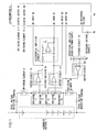
- a battery controller includes a divider resistor 20 constituted by four resistors and connected in parallel to an assembled battery 1, a differential amplifier constituted by buffer circuits 15 and 16 and a differential amplifier circuit 17, a buffer circuit 18 which applies a positive constant electric potential to the midpoint of the divider resistor 20, and a microcomputer 8 as a main control circuit.
- the assembled battery 1 according to the present embodiment is constituted by 96 lithium ion batteries with voltage rating of 3. 6V connected in series.
- the total voltage rating of the assembled battery 1 is 345.6V.
- a plurality of lithium ion batteries (for example, four batteries) are grouped into one group battery.
- a plurality of group batteries are connected in series in a battery case. This assures vibration resistance required for in-vehicle use and assures handleability and assemblability in production.
- the plus (+) terminal and the minus (-) terminal of the assembled battery 1 are each connected to a tinned total voltage detection terminal (connector).
- the total voltage detection terminals are each connected to a connector on the battery controller side. That is, the assembled battery 1 is connected via the total voltage detection terminals to a series circuit that includes a switching element 9 composed of an FET or the like, the divider resistor 20 constituted by resistors 11, 12, 13, and 14 connected in series, and a switching element 10 composed of an FET or the like.
- the resistors 11 and 14 are high-resistance (in the present embodiment, 10 M ⁇ each).
- the total voltage of the assembled battery 1 is divided into low voltages.
- the resistors 12 and 13 are resistors for voltage measurement (and voltage division), each of which is set to 50 k ⁇ in the present embodiment. Therefore, the assembled battery 1 and the battery controller are insulated from each other with insulation resistance of 5 M ⁇ . Division ratio between the resistors 11 and 12 as well as between the resistors 14 and 13 is both 50 / 10.05. Therefore, voltage of 0.86V is generated on both ends of the resistors 12 and 13 when the total voltage of the assembled battery 1 is 345.6V.
- resistor 21 One end of a resistor 21 is connected to a connection point of the switching element 9 and the resistor 11. The other end of the resistor 21 is connected to a connection point of the resistor 14 and the switching element 10. In other words, the resistor 21 is connected in parallel to the divider resistor 20.
- the resistor 21 increases current that flows through the total voltage detection terminal at the time of measuring the total voltage of the assembled battery 1.
- the resistor 21 is set to 200 k ⁇ in the present embodiment.
- Gates of the switching element 9 and the switching element 10 are respectively connected to digital output terminals 85 and 86 of the microcomputer 8.
- a binary high level signal is output from the microcomputer 8 to the gates of the switching elements 9 and 10 at the time of measuring the total voltage of the assembled battery 1, so as to control the switching elements 9 and 10 to be ON.
- the voltage is a value of an operating power supply of an operational amplifier divided by a divider circuit 19, which is constituted by two resistors.
- the voltage of the operating power supply is 5V.
- the voltage after the division (output voltage of the buffer circuit 18) is set to 2.5V.
- a connection point of the resistor 11 and the resistor 12 is connected to a positive phase input side of the differential amplifier circuit 17 via the buffer circuit 15. In other words, this connection point is connected to a positive phase input terminal of the differential amplifier via the resistor.
- a connection point of the resistor 13 and the resistor 14 is connected to a negative phase input side of the differential amplifier circuit 17 via the buffer circuit 16. In other words, this connection point is connected to a negative phase input terminal of the differential amplifier via the resistor.
- the output of the differential amplifier circuit 17 is connected to an A/D input terminal 81 of the microcomputer 8, which utilizes the reference voltage source 5 as a reference voltage.
- the microcomputer 8 measures (detects) the total voltage of the assembled battery 1. It should be noted that operational amplifiers used for the buffer circuits 15 and 16 and the differential amplifier circuit 17 are also operated by a single power supply. Therefore, a total of four operational amplifiers including the operational amplifier for the buffer circuit 18 are packed in a single package.
- voltage of the reference voltage source 5 is 5V.
- An amplification factor of the differential amplifier circuit 17 is set to double. A doubled value of the difference between input voltages to the positive phase input side and the negative phase input side of the differential amplifier circuit 17 is applied to the A/D input terminal 81 of the microcomputer 8. When the total voltage of the assembled battery 1 is 345.
- the input voltage to the positive phase input terminal is the sum (3.36V) of the voltage at the connection point of the resistors 11 and 12 (2.5V) and the voltage at the both ends of the resistor 12 (0.86V), while the input voltage to the negative phase input terminal is the difference (1.64V) between the voltage at the connection point of the resistors 11 and 12 (2.5V) and the voltage at the both ends of the resistor 13 (0.86V).
- the voltage at the A/D input terminal 81 of the microcomputer 8 is 3.36V.
- An A/D converter that utilizes the reference voltage source 5 as a reference voltage is incorporated into the microcomputer 8.
- An analog voltage input through the A/D input terminal 81 is converted to a digital voltage by the A/D converter and taken in to a CPU of the microcomputer 8.
- the microcomputer 8 is connected to the ground which is equipotential with a chassis of the hybrid electric vehicle.
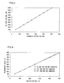
- FIG. 3 shows detection result of a voltage which is input to the A/D input terminal 81 of the microcomputer 8, with varying a voltage of the assembled battery 1.
- a voltage is actually applied to the A/D input terminal 81 as calculated.
- the total voltage of the assembled battery 1 and the voltage of the A/D input terminal 81 are in a linear relationship.
- the operational amplifier is operated by a single power supply. Specifically, the operational amplifier is operated when the input voltage ranges from 0V to a power supply voltage. According to the present embodiment, 1/2 of an operating power supply voltage is a voltage at the connection point of the resistors 12 and 13. Therefore, even if the electric potential of the battery controller (the microcomputer 8) to the ground fluctuates to some extent, the total voltage of the assembled battery 1 can normally be measured within the range of the operating voltage of the operational amplifier.
- FIG. 4 shows the total voltage detection characteristics when the plus (+) terminal of the assembled battery 1 is connected to the ground and when the minus (-) terminal of the assembled battery 1 is connected to the ground.
- the total voltage of the assembled battery 1 is normally detected even if either one of the terminals of the assembled battery 1 is connected to the ground.
- an inverter and a motor are used as load of an assembled battery. Therefore, a certain amount of noise is superimposed on the total voltage detection terminal of the assembled battery 1 to the ground, thereby fluctuating the electric potential.
- the total voltage can be normally measured even if the total voltage detection terminal of the assembled battery 1 fluctuates to the ground potential.
- an output terminal of the buffer circuit 15 (the positive phase input side of the differential amplifier circuit 17) is connected to an A/D input terminal 82 of the microcomputer 8.
- An output terminal of the buffer circuit 16 (the negative phase input side of the differential amplifier circuit 17) is connected to an A/D input terminal 83 of the microcomputer 8.
- An output terminal of the buffer circuit 18 (the connection point of the resistors 12 and 13, that is, the midpoint of the divider resistor 20) is connected to an A/D input terminal 84 of the microcomputer 8.
- another three A/D converters which utilizes the reference voltage source 5 as a reference voltage are incorporated into the microcomputer 8. Analog voltages input through the A/D input terminals 82 to 84 are each converted to a digital voltage by one of the three A/D converters and taken in to the CPU of the microcomputer 8.
- the microcomputer 8 includes an interface for a communication with a higher-level control device that controls an engine or the like of the hybrid electric vehicle.
- the microcomputer 8 informs the higher-level control device of the total voltage of the assembled battery 1 upon an instruction from the higher-level control device or at a predetermined time interval.
- the CPU controls the switching elements 9 and 10 to be ON with the digital output terminals 85 and 86 at high level and takes in a digital voltage value of the A/D converter connected to the A/D input terminal 81, so as to measure the total voltage of the assembled battery 1 at a predetermined time interval (for example, every 5 to 20ms) .
- the CPU informs at a predetermined time interval the higher-level control device of the total voltage value of the assembled battery 1 that has been measured. Based upon the total voltage value of the assembled battery 1 which has been informed, the higher-level control device performs motor torque calculation or the like so as to control the inverter that drives the motor or so as to control the engine.
- the CPU stops measuring the total voltage of the assembled battery 1 and controls the switching elements 9 and 10 to be OFF with the digital output terminals 85 and 86 at low level.
- the CPU detects at a predetermined time interval (5ms to 20ms) failures in: (1) the differential amplifier circuit 17, and (2) a bias potential output circuit (the buffer circuit 18 and the divider circuit 19).
- the CPU detects (measures) via the A/D converter which is incorporated therein input voltage values to the positive phase input side and the negative phase input side of the differential amplifier circuit 17 (output voltages of the buffer circuits 15 and 16) and an output voltage value of the differential amplifier circuit 17.
- the CPU calculates the value of " (output voltage value of the differential amplifier circuit 17) / ⁇ (input voltage value to the positive phase input side) - (input voltage value to the negative phase input side) ⁇ ".
- the CPU judges whether or not the obtained value is within a range of a predetermined amplification factor of the differential amplifier circuit 17 (in the present example, double). In case of the affirmative judgment (inside the range), the CPU judges the differential amplifier circuit 17 to be working normally. In case of the negative judgment (outside the range), the CPU judges the differential amplifier circuit 17 to be at fault.
- the CPU detects (measures) via the A/D converter which is incorporated therein an output voltage of the buffer circuit 18 and then judges whether or not the output voltage is within a predetermined range (for example, less than 2.0V). In case of the affirmative judgment (inside the range), the CPU judges the bias potential output circuit to be working normally. In case of the negative judgment (outside the range), the CPU judges the bias potential output circuit (particularly, the buffer circuit 18) to be at fault.
- a predetermined range for example, less than 2.0V
- the CPU detects every 5ms to 20ms failures in: (1) the differential amplifier circuit 17, and (2) the bias potential output circuit. It should be noted that the CPU does not draw a conclusion from a single failure detection. If the CPU does judge a plurality of failures consecutively, for example, within 100ms, the CPU informs the higher-level control device that: (1) the differential amplifier circuit 17 is at fault, or (2) the bias potential output circuit is at fault. Upon being informed, the higher-level control device displays that information on an instrument panel or, if necessary, gives a voice warning, so as to alert the driver.
- the battery controller includes the divider resistor 20, which is provided between the plus (+) terminal and the minus (-) terminal of the assembled battery 1.
- the divider resistor 20 is constituted by the series circuit that consists of the resistors 11, 12, 13, and 14.
- the connection point of the resistors 11 and 12 is connected to the positive phase input side of the differential amplifier circuit 17 via the buffer circuit 15.
- the connection point of the resistors 13 and 14 is connected to the negative phase input side of the differential amplifier circuit 17 via the buffer circuit 16.
- the constant electric potential (2.5V) relative to the ground of the microcomputer 8 is applied to the connection point of the resistors 12 and 13 (the midpoint of the divider resistor 20) so as to measure output voltage of the differential amplifier circuit 17.
- the total voltage of an assembled battery can be detected by using the A/D converter incorporated in the microcomputer 8, thereby reducing production cost.
- a reference source of the A/D converter can be shared with the reference voltage source 5 of the microcomputer 8. This eliminates the need of a special reference voltage source for an assembled battery total voltage detection circuit, and significantly reduces both the production cost and the number of components in comparison with conventional techniques.
- connection point of the resistors 11 and 12 is connected to the positive phase input side of the differential amplifier circuit 17 via the buffer 15.
- the connection point of the resistors 13 and 14 is connected to the negative phase input side of the differential amplifier circuit 17 via the buffer 16.
- General-purpose operational amplifiers operated by a single power supply are used for the buffer circuits 15 and 16, the differential amplifier circuit 17, and the buffer circuit 18 so as to reduce production cost. More specifically, these four general-purpose operational amplifiers are packed into a single package, thereby further reducing production cost.
- a positive constant electric potential (2. 5V) is applied to the midpoint of the divider resistor 20, that is, the connection point of the resistors 12 and 13 through the buffer 18. Therefore, impedance of the connection point of the resistors 12 and 13 to the ground can be reduced, thereby assuring noise-resistant, stable performance. It should be noted that a hybrid electric vehicle requires reliability of a battery controller to noise generated by an inverter or a motor.
- the resistor 21 is connected in parallel to the divider resistor 20.
- the resistor 21 has a resistance value of 200 k ⁇ , which is smaller than that of the divider resistor. If the resistor 21 is not connected in parallel, when the total voltage of the assembled battery 1 is 345.6V, a current as small as 17 ⁇ A flows through the total voltage detection terminal. Therefore, a costly gold-plated contact has to be used so as to assure reliability of contact point of the total voltage detection terminal. On the other hand, if the resistor 21 is connected in parallel, a current as large as 1.7 mA flows through the total voltage detection terminal. Therefore, even if a less-costly tinned contact or the like is used as in the present embodiment, reliability of contact point of the total voltage detection terminal is assured.
- the switching elements 9 and 10 are controlled to be ON at the time of measuring the total voltage of the assembled battery 1. This prevents electric discharge from the assembled battery 1 considerably, at times other than measuring the total voltage (in particular, while the hybrid electric vehicle is stopping).
- the battery controller according to the present embodiment automatically detects failures in: (1) the differential amplifier circuit 17, and (2) the bias potential output circuit. Therefore, safety and reliability are secured even on a moving vehicle such as a hybrid electric vehicle.
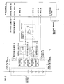
- FIG. 5 is a circuit diagram thereof, showing an example in which the buffer circuit 18 and the divider circuit 19 are removed from the circuit shown in FIG. 1 and the connection point of the resistors 12 and 13 is connected to the ground.
- a battery controller according to another example as the one described above has advantageous effects as the battery controller shown in FIG. 1 has.
- microcomputer 8 is used as a main control circuit in the example according to the present embodiment, the present invention is not limited to the above example.
- the present invention may be configured using a hardware including, for instance, an input-output circuit and a logic circuit.
- the present invention is not limited to the above example.
- the present invention may be applied to, for instance, a stationary power storage system.
- the power storage system may store an electric power generated by solar power or wind power.
- lithium ion batteries are used for a battery that constitutes an assembled battery in the example according to the present embodiment, the present invention is not limited to the above example.
- a nickel-metal hybrid battery or the like may be used.
- the present invention provides an assembled battery total voltage detection circuit with reliability at a low cost, it contributes to manufacturing and marketing of an assembled battery total voltage detection circuit, therefore it has industrial applicability.
- a constant electric potential relative to the ground of the main control circuit is applied to the midpoint of the divider resistor which is connected between the plus (+) terminal and the minus (-) terminal of the assembled battery as defined in the claims, and the voltage divided by the divider resistor is measured via the differential amplifier circuit. Therefore, the total voltage of the assembled battery can be detected without a costly insulation power source, and impedance of the midpoint of the divider resistor to the ground can be reduced, thereby assuring reliability related to noise-resistance.
Landscapes
- Engineering & Computer Science (AREA)
- Mechanical Engineering (AREA)
- Sustainable Development (AREA)
- Sustainable Energy (AREA)
- Power Engineering (AREA)
- Transportation (AREA)
- Life Sciences & Earth Sciences (AREA)
- Physics & Mathematics (AREA)
- General Physics & Mathematics (AREA)
- Measurement Of Current Or Voltage (AREA)
- Secondary Cells (AREA)
- Hybrid Electric Vehicles (AREA)
- Tests Of Electric Status Of Batteries (AREA)
- Electric Propulsion And Braking For Vehicles (AREA)
Claims (17)
- Circuit de détection de la tension totale d'une batterie assemblée, comprenant :un circuit de contrôle principal (8) ;une résistance diviseuse de tension (20) reliée à la borne positive et à la borne négative d'une batterie assemblée (1) de façon à isoler électriquement la batterie assemblée du circuit de contrôle principal ;un circuit amplificateur différentiel (15 - 17) destiné à amplifier la tension divisée par la résistance diviseuse de tension (20) et incluant un premier buffer (15, 16) et un amplificateur différentiel (17), caractérisé en ce que le premier buffer (15, 16) et l'amplificateur différentiel (17) sont chacun constitués d'un amplificateur opérationnel à alimentation simple, etun moyen d'application d'un potentiel électrique (18, 19) comprenant un deuxième buffer (18) constitué d'un amplificateur opérationnel à alimentation simple pour appliquer, par ledit buffer (18), un potentiel électrique positif constant par rapport à la masse du circuit de contrôle principal à un point médian de la résistance diviseuse de tension ; caractérisé en ce quele circuit de contrôle principal (8) comprend un moyen de mesure de la tension divisée par la résistance diviseuse de tension (20) appliquant ledit potentiel électrique constant à son point médian via le circuit amplificateur différentiel (17).
- Circuit selon la revendication 1, caractérisé en ce que
les amplificateurs opérationnels sont regroupés en une seule unité. - Circuit selon la revendication 1, comprenant également
une résistance (21) dont la valeur ohmique est inférieure à celle de la résistance diviseuse de tension (20), ladite résistance étant montée en parallèle à la résistance diviseuse de tension. - Circuit selon la revendication 3, comprenant également deux éléments de commutation (9, 10, l'un étant inséré entre la borne positive de la batterie assemblée (1) et la résistance diviseuse de tension, l'autre étant inséré entre la borne négative de la batterie assemblée (1) et la résistance diviseuse de tension, caractérisé en ce que
le circuit de contrôle principal (8) comprend un moyen de mesure de la tension totale de la batterie assemblée (1) afin de contrôler que les éléments de commutation (9, 10) soient sur ON, et de mesurer la tension divisée par la résistance diviseuse de tension (20) via le circuit amplificateur différentiel (17). - Circuit selon l'une des revendications 1 à 4, caractérisé en ce que
le circuit de contrôle principal (8) inclut une première unité de détection de défaillance qui exécute la détection de défaillance pour le circuit amplificateur différentiel (17). - Circuit selon au moins une des revendications 1 à 5, caractérisé en ce que
le circuit de contrôle principal (8) inclut une deuxième unité de détection de défaillance qui exécute la détection de défaillance pour le buffer. - Circuit selon la revendication 1, caractérisé en ce que :la résistance diviseuse de tension (20) est constituée d'un circuit en série composé d'une première, d'une deuxième, d'une troisième et d'une quatrième résistance (11-14) ;le circuit amplificateur différentiel (17) inclut une borne d'entrée de phase positive reliée à un point de connexion de la première et de la deuxième résistance (11, 12), et une borne d'entrée de phase négative reliée à un point de connexion de la troisième et de la quatrième résistance (13, 14), etle potentiel électrique constant par rapport à la masse du circuit de contrôle principal est appliqué à un point de connexion de la deuxième et de la troisième résistance (12, 13), le circuit de contrôle principal (8) comprenant un moyen de mesure de la tension de sortie du circuit amplificateur différentiel (17).
- Circuit selon la revendication 7, caractérisé en ce que
le circuit amplificateur différentiel (17) inclut le premier buffer et l'amplificateur différentiel. - Circuit selon la revendication 8, caractérisé en ce que :le circuit amplificateur différentiel (17) inclut le premier buffer (15) et un troisième buffer (16) ;le point de connexion de la première et de la deuxième résistance (11, 12) est relié à une borne d'entrée du premier buffer (15) ;le point de connexion de la troisième et de la quatrième résistance (13, 14) est relié à une borne d'entrée du troisième buffer (16) ; etles bornes de sortie du premier et du troisième buffer (15, 16) sont respectivement reliées à la borne d'entrée de phase positive et à la borne d'entrée de phase négative de l'amplificateur différentiel (17).
- Circuit selon la revendication 9, caractérisé en ce que
le premier et le troisième buffer (15, 16) ainsi que l'amplificateur différentiel (17) sont chacun constitués d'un amplificateur opérationnel à alimentation simple. - Circuit selon la revendication 7, caractérisé en ce que
le moyen d'application du potentiel électrique (18, 19) inclut le deuxième buffer (18) constitué d'un amplificateur opérationnel à alimentation simple, et
le potentiel électrique est appliqué au point de connexion de la deuxième et de la troisième résistance (12, 13) en utilisant le deuxième buffer (18). - Circuit selon la revendication 10 ou la revendication 11, caractérisé en ce que
une pluralité d'amplificateurs opérationnels sont regroupés en une seule unité. - Circuit selon au moins une des revendications 7 à 12, comprenant également :un premier et un deuxième élément de commutation (9, 10), le premier élément de commutation (9) étant inséré entre la borne positive de la batterie assemblée (1) et la première résistance (11), le deuxième élément de commutation (10) étant inséré entre la borne négative de la batterie assemblée (1) et la quatrième résistance (14) ; etune résistance (21) dont la valeur ohmique est inférieure à celle de la somme des première, deuxième, troisième et quatrième résistances (11-14), ladite résistance étant montée en parallèle entre un point de connexion auquel sont reliés le premier élément de commutation (9) et la première résistance (11), et un point de connexion auquel sont reliés le deuxième élément de commutation (10) et la quatrième résistance (14), caractérisé en ce quele circuit de contrôle principal (8) comprend un moyen de contrôle destiné à contrôler que le premier et le deuxième élément de commutation (9, 10) soient sur ON, ainsi qu'à mesurer la tension entre le point de connexion de la première et de la deuxième résistance (11, 12) et le point de connexion de la troisième et de la quatrième résistance (13, 14) via le circuit amplificateur différentiel (17) afin de mesurer la tension totale de la batterie assemblée (1).
- Circuit selon la revendication 1, caractérisé en ce que :la résistance diviseuse de tension (20) est constituée d'un circuit en série composé d'une première, d'une deuxième, d'une troisième et d'une quatrième résistance (11-14) ;le circuit amplificateur différentiel (17) inclut une borne d'entrée de phase positive reliée à un point de connexion de la première et de la deuxième résistance (11, 12), et une borne d'entrée de phase négative reliée à un point de connexion de la troisième et de la quatrième résistance (13, 14), etle potentiel électrique constant par rapport à la masse du circuit de contrôle principal est appliqué à un point de connexion de la deuxième et de la troisième résistance (12, 13) en utilisant le deuxième buffer (18) ; etle circuit de contrôle principal (8) est destiné à mesurer la tension de sortie du circuit amplificateur différentiel (17) afin de mesurer la tension totale de la batterie assemblée, et inclut une première unité de détection de défaillance qui exécute la détection de défaillance pour le circuit amplificateur différentiel (17) .
- Circuit selon la revendication 14, caractérisé en ce que
la première unité de détection de défaillance comprend un moyen de détection des valeurs de tension d'entrée sur le côté d'entrée de phase positive et le côté d'entrée de phase négative du circuit amplificateur différentiel (17), et d'une valeur de tension de sortie sur le côté de sortie du circuit amplificateur différentiel (17), et comprend un moyen de contrôler si le circuit amplificateur différentiel (17) est défaillant, au cas où une valeur v se trouverait en dehors de la plage déterminée pour le facteur d'amplification du circuit amplificateur différentiel, v résultant de
où ovv est la valeur de tension de sortie du circuit amplificateur différentiel, ivp la valeur de tension d'entrée sur le côté d'entrée de phase positive, et ivn la valeur de tension d'entrée sur le côté d'entrée de phase négative. - Circuit selon la revendication 14, caractérisé en ce que
le circuit de contrôle principal (8) inclut également une deuxième unité de détection de défaillance pou exécuter la détection de défaillance pour le buffer (18) . - Circuit selon la revendication 16, caractérisé en ce que
la deuxième unité de détection de défaillance comprend un moyen de détecter une valeur de tension de sortie du buffer (18), et, si la valeur de tension de sortie détectée se trouve en dehors de la plage déterminée, de juger si le buffer est défaillant.
Applications Claiming Priority (1)
| Application Number | Priority Date | Filing Date | Title |
|---|---|---|---|
| JP2008083786A JP4649489B2 (ja) | 2008-03-27 | 2008-03-27 | 組電池の総電圧検出回路 |
Publications (2)
| Publication Number | Publication Date |
|---|---|
| EP2105753A1 EP2105753A1 (fr) | 2009-09-30 |
| EP2105753B1 true EP2105753B1 (fr) | 2013-05-22 |
Family
ID=40759649
Family Applications (1)
| Application Number | Title | Priority Date | Filing Date |
|---|---|---|---|
| EP09002477.9A Active EP2105753B1 (fr) | 2008-03-27 | 2009-02-20 | Circuit de détection de tension totale de batterie assemblée |
Country Status (4)
| Country | Link |
|---|---|
| US (1) | US8760168B2 (fr) |
| EP (1) | EP2105753B1 (fr) |
| JP (1) | JP4649489B2 (fr) |
| CN (2) | CN103743943B (fr) |
Families Citing this family (61)
| Publication number | Priority date | Publication date | Assignee | Title |
|---|---|---|---|---|
| CN101825687B (zh) * | 2009-03-06 | 2012-06-13 | 鸿富锦精密工业(深圳)有限公司 | 电量侦测装置 |
| US8442727B2 (en) * | 2009-06-05 | 2013-05-14 | Toyota Jidosha Kabushiki Kaisha | Electric vehicle and method for setting total allowable discharge electric energy in the electric vehicle |
| EP2508904B8 (fr) * | 2009-12-03 | 2019-05-22 | Toshiba Mitsubishi-Electric Industrial Systems Corporation | Système de batterie secondaire |
| JP5497421B2 (ja) * | 2009-12-24 | 2014-05-21 | Necエナジーデバイス株式会社 | 多直列リチウムイオン二次電池情報伝達システム |
| US8736273B2 (en) * | 2010-04-15 | 2014-05-27 | Lg Chem, Ltd. | Testing system and method for testing a battery cell |
| JP2012018037A (ja) * | 2010-07-07 | 2012-01-26 | Nec Energy Devices Ltd | 電圧測定回路及び方法 |
| DE102010026919A1 (de) * | 2010-07-13 | 2012-01-19 | Leopold Kostal Gmbh & Co. Kg | Verfahren zur Erfassung einer Schaltstellung einer Schalteinrichtung |
| JP2012049434A (ja) * | 2010-08-30 | 2012-03-08 | Sony Corp | 電子部品、給電装置、受電装置、およびワイヤレス給電システム |
| US9568555B2 (en) * | 2010-12-06 | 2017-02-14 | Peter Fredrick Nortman | Electrochemical cell monitoring and balancing circuit with self-diagnostic feature |
| CN102081146A (zh) * | 2010-12-09 | 2011-06-01 | 奇瑞汽车股份有限公司 | 一种高压电池电压检测装置 |
| JP6033529B2 (ja) * | 2011-05-30 | 2016-11-30 | 株式会社東海理化電機製作所 | 検出装置および電流センサ |
| US9340122B2 (en) | 2011-05-31 | 2016-05-17 | Hitachi Automotive Systems, Ltd. | Battery system monitoring apparatus |
| FR2976085B1 (fr) * | 2011-06-01 | 2014-02-28 | Commissariat Energie Atomique | Dispositif de detection d'un defaut d'isolement |
| WO2013051484A1 (fr) * | 2011-10-03 | 2013-04-11 | パナソニック株式会社 | Dispositif de charge en énergie destiné à un véhicule électrique |
| CN103064024A (zh) * | 2011-10-18 | 2013-04-24 | 立锜科技股份有限公司 | 电池电量估计装置 |
| US8716981B2 (en) | 2011-11-11 | 2014-05-06 | Lg Chem, Ltd. | System and method for cooling and cycling a battery pack |
| CN103134979A (zh) * | 2011-11-28 | 2013-06-05 | 同济大学 | 一种用于储能器件端电压的巡检电路 |
| US8816692B2 (en) | 2011-12-01 | 2014-08-26 | Lg Chem, Ltd. | Test system for a battery module |
| JP5885138B2 (ja) * | 2011-12-06 | 2016-03-15 | 有限会社アイ・アール・ティー | 電圧検出装置及び電力検出装置 |
| KR101854456B1 (ko) * | 2011-12-12 | 2018-05-03 | 현대모비스 주식회사 | 배터리 센서 및 배터리 모니터링 시스템 |
| JPWO2013161069A1 (ja) * | 2012-04-27 | 2015-12-21 | パナソニックIpマネジメント株式会社 | 太陽電池モジュール及び太陽電池モジュールの製造方法 |
| US9231407B2 (en) * | 2012-05-07 | 2016-01-05 | Samsung Sdi Co., Ltd. | Battery system, method of controlling the same, and energy storage system including the battery system |
| CN103531222A (zh) * | 2012-07-06 | 2014-01-22 | 鸿富锦精密工业(深圳)有限公司 | 硬盘 |
| US9063179B2 (en) | 2012-09-26 | 2015-06-23 | Lg Chem, Ltd. | System and method for determining an isolation resistance of a battery pack disposed on a vehicle chassis |
| CN105164541B (zh) * | 2013-04-26 | 2018-04-06 | 日立汽车系统株式会社 | 电池监视装置和使用该电池监视装置的电池系统 |
| DE112014002675T5 (de) * | 2013-06-04 | 2016-02-18 | Trw Automotive U.S. Llc | Optimierte Spannungsversorgungsarchitektur |
| CN103353581B (zh) * | 2013-06-25 | 2015-10-21 | 安徽力高新能源技术有限公司 | 一种电池组高压状态复合检测装置 |
| CN103336204B (zh) * | 2013-06-26 | 2015-12-09 | 天津市三源电力设备制造有限公司 | 一种电压型超级电容检测电路 |
| US9164151B2 (en) | 2013-08-07 | 2015-10-20 | Lg Chem, Ltd. | System and method for determining isolation resistances of a battery pack |
| KR102136228B1 (ko) * | 2013-12-13 | 2020-07-21 | 에스케이하이닉스 주식회사 | 차동 시그널링을 지원하는 송/수신기 및 이를 포함하는 반도체 송/수신 시스템 |
| CN103823104B (zh) * | 2014-02-24 | 2016-08-31 | 中国航天时代电子公司 | 一种单电源供电的自动量程正负电压测量电路 |
| KR102206734B1 (ko) | 2014-04-30 | 2021-01-25 | 삼성전자주식회사 | 배터리 팩의 전압을 측정하는 방법 및 장치 |
| JP2016057264A (ja) * | 2014-09-12 | 2016-04-21 | Ntn株式会社 | バッテリーチェッカー |
| CN104237624B (zh) * | 2014-10-08 | 2017-04-12 | 武汉弈飞科技有限公司 | 一种电动汽车直流高压传感器及其采样方法 |
| JP6478200B2 (ja) * | 2014-10-17 | 2019-03-06 | 株式会社ケーヒン | 電源電圧検出装置 |
| KR101610908B1 (ko) | 2014-11-17 | 2016-04-20 | 현대오트론 주식회사 | 배터리 전압 측정회로의 진단 장치 및 그 방법 |
| KR101746141B1 (ko) * | 2015-03-10 | 2017-06-13 | 주식회사 엘지화학 | 절연저항측정 장치 및 방법 |
| CN108076678B (zh) * | 2015-08-27 | 2020-06-09 | 日立汽车系统株式会社 | 逆变器控制装置 |
| CN105425155B (zh) * | 2015-11-03 | 2018-09-25 | 惠州市蓝微新源技术有限公司 | 一种高压电池组总电压和绝缘电阻检测电路及检测方法 |
| CN106706996A (zh) * | 2015-11-18 | 2017-05-24 | 上海航天汽车机电股份有限公司 | 一种电机电流检测信号的放大电路 |
| CN105353320B (zh) * | 2015-12-08 | 2019-05-10 | 北京科易动力科技有限公司 | 一种基于串联电池组的电池组间通讯电路及通讯方法 |
| CN205920152U (zh) * | 2016-07-20 | 2017-02-01 | 周鄂林 | 一种电池电压检测电路及鼻毛器 |
| JP6685196B2 (ja) * | 2016-07-21 | 2020-04-22 | 株式会社日立国際電気 | 電圧検出回路 |
| KR101960293B1 (ko) * | 2017-02-14 | 2019-03-20 | 에스케이이노베이션 주식회사 | 절연저항 측정방법 및 측정장치 |
| CN108663622B (zh) * | 2017-03-30 | 2020-06-12 | 深圳市理邦精密仪器股份有限公司 | 电池组电压测量电路及电压测量系统 |
| US10476502B2 (en) * | 2017-04-28 | 2019-11-12 | Cirrus Logic, Inc. | Control of switches in a variable impedance element |
| CN107727923A (zh) * | 2017-08-29 | 2018-02-23 | 宁德时代新能源科技股份有限公司 | 高压采样电路和电池管理系统 |
| CN110021992B (zh) * | 2018-01-10 | 2022-02-18 | 厦门雅迅网络股份有限公司 | 一种主备电源切换电路及方法 |
| CN108333492B (zh) | 2018-02-01 | 2021-01-01 | 宁德时代新能源科技股份有限公司 | 绝缘检测电路及方法、电池管理系统 |
| TWI692165B (zh) | 2018-02-02 | 2020-04-21 | 飛捷科技股份有限公司 | 電池供電系統及其方法 |
| EP3758188B1 (fr) * | 2018-02-23 | 2023-12-20 | Nuvoton Technology Corporation Japan | Dispositif de mesure de tension, circuit de détection de tension et procédé de génération d'adresse de dispositif |
| CN110333457B (zh) * | 2018-03-28 | 2021-04-16 | 上海汽车集团股份有限公司 | 一种动力电池组电压采样电路、动力系统及新能源汽车 |
| JP7091800B2 (ja) * | 2018-04-16 | 2022-06-28 | 株式会社デンソー | 回路基板 |
| CN109038762B (zh) * | 2018-09-14 | 2020-07-14 | 珠海格力电器股份有限公司 | 充电装置与充电系统 |
| CN110824374A (zh) * | 2019-12-13 | 2020-02-21 | 浙江高泰昊能科技有限公司 | 一种低成本的高压系统总压检测电路 |
| IL273496A (en) * | 2020-03-22 | 2021-09-30 | Irp Nexus Group Ltd | A system and application for managing a battery array |
| JP7310747B2 (ja) | 2020-07-28 | 2023-07-19 | 株式会社デンソー | 電圧検出装置 |
| JP7403488B2 (ja) * | 2021-02-18 | 2023-12-22 | 三菱電機株式会社 | 電流信号処理装置 |
| JP7778149B2 (ja) * | 2021-08-03 | 2025-12-01 | ソニーセミコンダクタソリューションズ株式会社 | 負電圧監視回路及び受光装置 |
| JP2023123979A (ja) * | 2022-02-25 | 2023-09-06 | 日本特殊陶業株式会社 | ガスセンサ |
| CN118534183A (zh) * | 2024-05-14 | 2024-08-23 | 深蓝汽车科技有限公司 | 一种继电器外侧总电压确定方法、装置、车辆及存储介质 |
Family Cites Families (19)
| Publication number | Priority date | Publication date | Assignee | Title |
|---|---|---|---|---|
| JP3590679B2 (ja) | 1995-09-18 | 2004-11-17 | 株式会社ケーヒン | 浮動直流電源の異常検出装置 |
| JPH11248756A (ja) * | 1998-03-06 | 1999-09-17 | Matsushita Electric Ind Co Ltd | フライング・キャパシタ回路 |
| DE69937220T2 (de) * | 1998-03-06 | 2008-07-03 | Matsushita Electric Industrial Co., Ltd., Kadoma | Spannungsmessvorrichtung mit fliegendem kondensator |
| JP2001124805A (ja) | 1999-10-25 | 2001-05-11 | Yazaki Corp | 非絶縁型電圧センサ |
| JP3600211B2 (ja) | 2000-02-22 | 2004-12-15 | 三洋電機株式会社 | 電源装置の漏電検出回路 |
| JP3791767B2 (ja) * | 2001-03-27 | 2006-06-28 | 株式会社デンソー | フライングキャパシタ式電圧検出回路 |
| JP3760831B2 (ja) * | 2001-10-16 | 2006-03-29 | 日産自動車株式会社 | 組電池の電圧検出装置 |
| JP2003158187A (ja) * | 2001-11-21 | 2003-05-30 | Seiko Instruments Inc | バッテリー電圧検出回路 |
| JP3823840B2 (ja) * | 2002-02-14 | 2006-09-20 | 日産自動車株式会社 | 組電池の電圧検出装置 |
| JP4108360B2 (ja) * | 2002-04-25 | 2008-06-25 | シャープ株式会社 | 表示駆動装置およびそれを用いた表示装置 |
| DE10300539B4 (de) | 2003-01-09 | 2007-05-24 | Daimlerchrysler Ag | Schaltung und Verfahren zur Erfassung von Isolationsfehlern |
| JP4416585B2 (ja) * | 2004-07-06 | 2010-02-17 | 三洋電機株式会社 | 車両用の電源装置 |
| JP2007010316A (ja) * | 2005-06-28 | 2007-01-18 | Toyota Motor Corp | フライングキャパシタ式電圧検出装置 |
| JP4749132B2 (ja) * | 2005-11-21 | 2011-08-17 | 富士通セミコンダクター株式会社 | センサ検出装置及びセンサ |
| JP4785627B2 (ja) * | 2006-06-08 | 2011-10-05 | 三洋電機株式会社 | 電動車両用漏電検出回路および電動車両用漏電検出方法 |
| JP4533357B2 (ja) * | 2006-09-06 | 2010-09-01 | 日立ビークルエナジー株式会社 | 電圧測定装置 |
| JP4241787B2 (ja) | 2006-09-06 | 2009-03-18 | 日立ビークルエナジー株式会社 | 組電池総電圧検出およびリーク検出装置 |
| JP4566964B2 (ja) * | 2006-09-06 | 2010-10-20 | 日立ビークルエナジー株式会社 | 総電池電圧検出装置 |
| JP4257356B2 (ja) | 2006-09-26 | 2009-04-22 | 株式会社日立製作所 | 画像生成装置および画像生成方法 |
-
2008
- 2008-03-27 JP JP2008083786A patent/JP4649489B2/ja active Active
-
2009
- 2009-02-19 US US12/388,817 patent/US8760168B2/en active Active
- 2009-02-20 CN CN201310743519.4A patent/CN103743943B/zh active Active
- 2009-02-20 EP EP09002477.9A patent/EP2105753B1/fr active Active
- 2009-02-20 CN CN200910004953A patent/CN101545955A/zh active Pending
Also Published As
| Publication number | Publication date |
|---|---|
| JP4649489B2 (ja) | 2011-03-09 |
| EP2105753A1 (fr) | 2009-09-30 |
| JP2009236711A (ja) | 2009-10-15 |
| US8760168B2 (en) | 2014-06-24 |
| CN103743943B (zh) | 2016-09-28 |
| CN101545955A (zh) | 2009-09-30 |
| US20090243621A1 (en) | 2009-10-01 |
| CN103743943A (zh) | 2014-04-23 |
Similar Documents
| Publication | Publication Date | Title |
|---|---|---|
| EP2105753B1 (fr) | Circuit de détection de tension totale de batterie assemblée | |
| US10928459B2 (en) | Battery detection circuit and battery management system | |
| JP4589888B2 (ja) | 電池電圧測定回路、およびバッテリecu | |
| US7952327B2 (en) | Assembled battery total voltage detection and leak detection apparatus | |
| EP2413148B1 (fr) | Circuit de mesure de la résistance d'isolement non influencé par la tension de batterie | |
| JP4785627B2 (ja) | 電動車両用漏電検出回路および電動車両用漏電検出方法 | |
| CN100593725C (zh) | 电动车辆用漏电检测电路及电动车辆用漏电检测方法 | |
| US9404956B2 (en) | Vehicle with selectable battery pack isolation detection circuitry using precision resistors | |
| EP2172784A1 (fr) | Dispositif de détection de tension et système d'alimentation électrique utilisant ce dispositif | |
| US20150070023A1 (en) | Battery monitoring device and battery system monitoring device | |
| JP2013140162A (ja) | 絶縁抵抗測定回路 | |
| CN104627011A (zh) | 电动车辆蓄电池組电压监测系统和方法 | |
| DE102011088893A1 (de) | Strommessschaltung, Batterie und Kraftfahrzeug | |
| EP3901640B1 (fr) | Appareil de mesure de la résistance d'isolation | |
| CN1241259A (zh) | 电池电压测定装置 | |
| US10850618B2 (en) | Connection module for an electrical energy storage device, and power supply system | |
| EP4068545B1 (fr) | Dispositif de détection de fuite à la terre et système d'alimentation électrique de véhicule | |
| WO2022137705A1 (fr) | Circuit de détection de tension | |
| JP4583219B2 (ja) | 車両用の電源装置 | |
| JP5779060B2 (ja) | 電圧検出回路 | |
| JP2006353020A (ja) | 車両用の電源装置 | |
| JP4479086B2 (ja) | 組電池の電圧検出装置 | |
| JP4789669B2 (ja) | 車両用の電源装置とこの電源装置の基準接続ラインの断線を検出する方法 | |
| JP4554452B2 (ja) | 蓄電素子の電圧検出装置 |
Legal Events
| Date | Code | Title | Description |
|---|---|---|---|
| PUAI | Public reference made under article 153(3) epc to a published international application that has entered the european phase |
Free format text: ORIGINAL CODE: 0009012 |
|
| AK | Designated contracting states |
Kind code of ref document: A1 Designated state(s): AT BE BG CH CY CZ DE DK EE ES FI FR GB GR HR HU IE IS IT LI LT LU LV MC MK MT NL NO PL PT RO SE SI SK TR |
|
| AX | Request for extension of the european patent |
Extension state: AL BA RS |
|
| 17P | Request for examination filed |
Effective date: 20091002 |
|
| 17Q | First examination report despatched |
Effective date: 20091102 |
|
| AKX | Designation fees paid |
Designated state(s): DE FR GB IT |
|
| GRAP | Despatch of communication of intention to grant a patent |
Free format text: ORIGINAL CODE: EPIDOSNIGR1 |
|
| GRAS | Grant fee paid |
Free format text: ORIGINAL CODE: EPIDOSNIGR3 |
|
| GRAA | (expected) grant |
Free format text: ORIGINAL CODE: 0009210 |
|
| AK | Designated contracting states |
Kind code of ref document: B1 Designated state(s): DE FR GB IT |
|
| REG | Reference to a national code |
Ref country code: GB Ref legal event code: FG4D |
|
| REG | Reference to a national code |
Ref country code: DE Ref legal event code: R096 Ref document number: 602009015807 Country of ref document: DE Effective date: 20130725 |
|
| PLBE | No opposition filed within time limit |
Free format text: ORIGINAL CODE: 0009261 |
|
| STAA | Information on the status of an ep patent application or granted ep patent |
Free format text: STATUS: NO OPPOSITION FILED WITHIN TIME LIMIT |
|
| 26N | No opposition filed |
Effective date: 20140225 |
|
| REG | Reference to a national code |
Ref country code: DE Ref legal event code: R097 Ref document number: 602009015807 Country of ref document: DE Effective date: 20140225 |
|
| REG | Reference to a national code |
Ref country code: DE Ref legal event code: R082 Ref document number: 602009015807 Country of ref document: DE Representative=s name: BEETZ & PARTNER PATENT- UND RECHTSANWAELTE, DE |
|
| REG | Reference to a national code |
Ref country code: GB Ref legal event code: 732E Free format text: REGISTERED BETWEEN 20140828 AND 20140903 |
|
| REG | Reference to a national code |
Ref country code: DE Ref legal event code: R082 Ref document number: 602009015807 Country of ref document: DE Representative=s name: BEETZ & PARTNER PATENT- UND RECHTSANWAELTE, DE Effective date: 20140903 Ref country code: DE Ref legal event code: R081 Ref document number: 602009015807 Country of ref document: DE Owner name: HITACHI AUTOMOTIVE SYSTEMS, LTD., HITACHINAKA-, JP Free format text: FORMER OWNER: HITACHI, LTD., HITACHI VEHICLE ENERGY, LTD., , JP Effective date: 20140903 Ref country code: DE Ref legal event code: R081 Ref document number: 602009015807 Country of ref document: DE Owner name: HITACHI, LTD., JP Free format text: FORMER OWNER: HITACHI, LTD., HITACHI VEHICLE ENERGY, LTD., , JP Effective date: 20140903 Ref country code: DE Ref legal event code: R082 Ref document number: 602009015807 Country of ref document: DE Representative=s name: BEETZ & PARTNER MBB, DE Effective date: 20140903 Ref country code: DE Ref legal event code: R081 Ref document number: 602009015807 Country of ref document: DE Owner name: HITACHI AUTOMOTIVE SYSTEMS, LTD., HITACHINAKA-, JP Free format text: FORMER OWNERS: HITACHI, LTD., TOKYO, JP; HITACHI VEHICLE ENERGY, LTD., HITACHINAKA-SHI, IBARAKI, JP Effective date: 20140903 Ref country code: DE Ref legal event code: R081 Ref document number: 602009015807 Country of ref document: DE Owner name: HITACHI, LTD., JP Free format text: FORMER OWNERS: HITACHI, LTD., TOKYO, JP; HITACHI VEHICLE ENERGY, LTD., HITACHINAKA-SHI, IBARAKI, JP Effective date: 20140903 Ref country code: DE Ref legal event code: R082 Ref document number: 602009015807 Country of ref document: DE Representative=s name: BEETZ & PARTNER MBB PATENTANWAELTE, DE Effective date: 20140903 Ref country code: DE Ref legal event code: R082 Ref document number: 602009015807 Country of ref document: DE Representative=s name: BEETZ & PARTNER MBB PATENT- UND RECHTSANWAELTE, DE Effective date: 20140903 |
|
| REG | Reference to a national code |
Ref country code: FR Ref legal event code: TQ Owner name: HITACHI AUTOMOTIVE SYSTEMS, LTD., JP Effective date: 20141002 Ref country code: FR Ref legal event code: TQ Owner name: HITACHI LTD., JP Effective date: 20141002 |
|
| REG | Reference to a national code |
Ref country code: FR Ref legal event code: PLFP Year of fee payment: 8 |
|
| REG | Reference to a national code |
Ref country code: FR Ref legal event code: PLFP Year of fee payment: 9 |
|
| REG | Reference to a national code |
Ref country code: FR Ref legal event code: PLFP Year of fee payment: 10 |
|
| PGFP | Annual fee paid to national office [announced via postgrant information from national office to epo] |
Ref country code: GB Payment date: 20260121 Year of fee payment: 18 |
|
| PGFP | Annual fee paid to national office [announced via postgrant information from national office to epo] |
Ref country code: DE Payment date: 20260121 Year of fee payment: 18 |
|
| PGFP | Annual fee paid to national office [announced via postgrant information from national office to epo] |
Ref country code: IT Payment date: 20260121 Year of fee payment: 18 |
|
| PGFP | Annual fee paid to national office [announced via postgrant information from national office to epo] |
Ref country code: FR Payment date: 20260121 Year of fee payment: 18 |