EP2105812A2 - Steuerungssystem für Glaswarenformmaschine - Google Patents
Steuerungssystem für Glaswarenformmaschine Download PDFInfo
- Publication number
- EP2105812A2 EP2105812A2 EP09156209A EP09156209A EP2105812A2 EP 2105812 A2 EP2105812 A2 EP 2105812A2 EP 09156209 A EP09156209 A EP 09156209A EP 09156209 A EP09156209 A EP 09156209A EP 2105812 A2 EP2105812 A2 EP 2105812A2
- Authority
- EP
- European Patent Office
- Prior art keywords
- automatisms
- control
- actuating mechanisms
- activation
- machine
- Prior art date
- Legal status (The legal status is an assumption and is not a legal conclusion. Google has not performed a legal analysis and makes no representation as to the accuracy of the status listed.)
- Ceased
Links
Images


Classifications
-
- G—PHYSICS
- G05—CONTROLLING; REGULATING
- G05B—CONTROL OR REGULATING SYSTEMS IN GENERAL; FUNCTIONAL ELEMENTS OF SUCH SYSTEMS; MONITORING OR TESTING ARRANGEMENTS FOR SUCH SYSTEMS OR ELEMENTS
- G05B19/00—Program-control systems
- G05B19/02—Program-control systems electric
- G05B19/04—Program control other than numerical control, i.e. in sequence controllers or logic controllers
- G05B19/042—Program control other than numerical control, i.e. in sequence controllers or logic controllers using digital processors
-
- C—CHEMISTRY; METALLURGY
- C03—GLASS; MINERAL OR SLAG WOOL
- C03B—MANUFACTURE, SHAPING, OR SUPPLEMENTARY PROCESSES
- C03B9/00—Blowing glass; Production of hollow glass articles
- C03B9/30—Details of blowing glass; Use of materials for the moulds
- C03B9/40—Gearing or controlling mechanisms specially adapted for glass-blowing machines
- C03B9/41—Electric or electronic systems
-
- G—PHYSICS
- G05—CONTROLLING; REGULATING
- G05B—CONTROL OR REGULATING SYSTEMS IN GENERAL; FUNCTIONAL ELEMENTS OF SUCH SYSTEMS; MONITORING OR TESTING ARRANGEMENTS FOR SUCH SYSTEMS OR ELEMENTS
- G05B2219/00—Program-control systems
- G05B2219/20—Pc systems
- G05B2219/26—Pc applications
- G05B2219/2635—Glass forming
-
- G—PHYSICS
- G05—CONTROLLING; REGULATING
- G05B—CONTROL OR REGULATING SYSTEMS IN GENERAL; FUNCTIONAL ELEMENTS OF SUCH SYSTEMS; MONITORING OR TESTING ARRANGEMENTS FOR SUCH SYSTEMS OR ELEMENTS
- G05B2219/00—Program-control systems
- G05B2219/30—Nc systems
- G05B2219/45—Nc applications
- G05B2219/45009—Glassforming
Definitions
- the present invention relates to a control system for a glassware, in particular, hollow glassware, molding machine.
- Glassware is known to be molded on what are known as I.S. (Individual Section) molding machines, which comprise a feed assembly for supplying a succession of glass gobs; and a number of simultaneously, independently operating forming sections, each of which has a mold assembly, is fed by the feed assembly with respective glass gobs, and successively forms respective glass articles.
- the feed assembly comprises: an extruder for forming a rope of molten glass; a scissor cutting assembly for cutting the rope crosswise into a succession of glass gobs; a gob distributor, receiving the gobs from the cutting assembly; and, for each mold assembly in the forming sections, a respective gob dispenser for receiving the glass gobs from the distributor and feeding them to the associated mold assembly.
- the glass articles are expelled from the molds by respective actuator assemblies, which expel and convey each glass article from the respective mold onto a common conveyor; this common conveyor transfers the glass articles to a furnace.
- Each forming section comprises a large number of actuating mechanisms, some shared by a number of sections and others specific to a given section (such as mechanisms for handling or processing the rough-molded articles during the molding process, mold opening and closing mechanisms, etc.), which are controlled by a number of actuators, including electric and pneumatic actuators, and servomechanisms.
- Operation of I.S. machines therefore involves complex joint control of all the actuating mechanisms to carry out a given production plan (or recipe) based, for example, on the type of article being produced or the type of process adopted to produce it.
- the various actuating mechanisms have to be synchronized to ensure the set production plan is carried out correctly.
- control systems currently employed in I.S. machines have what is known as a "distributed-intelligence" architecture, which envisages the presence of a number of appropriately interconnected intelligent control units (controllers, provided with respective microprocessor computers).
- automatisms are divided into a given number of functional blocks (known as "automatisms"), each with its own control unit.
- the automatisms may, for example, correspond to the various forming sections of the I.S. machine, or may include operating mechanisms involved in the same function, regardless of their location within the various forming sections. Whichever the case, each control unit performs processing operations, on the basis of the set production plan, to determine timings of activation (i.e. implementing the automation of) the respective actuating mechanisms, and has to be coordinated with the other control units to carry out the glassware molding plan.
- control systems normally comprise a communications bus (e.g. a high-speed fieldbus) by which the control units of the various automatisms dialogue with one another.
- a communications bus e.g. a high-speed fieldbus
- the automatisms are synchronized using clock generators which supply common timing signals to the various control units.
- control systems normally also comprise a supervisor connected to the automatism control units, and which performs production planning operations, and transmits set production plan data to the control units.
- the supervisor may, for example, comprise an industrial PC (Personal Computer) with a user interface for operator production plan control.
- EP-B-1 537 052 discloses a glassware molding machine control system comprising three control units for independent "intelligent" control of respective automatisms as a function of a given production plan, and in particular: a first control unit relating to a glass gob feed assembly; a second control unit relating to a glassware forming assembly; and a third control unit relating to a glassware handling assembly.
- the three control units are interconnected by a serial data bus to coordinate and synchronize operations of the respective operating assemblies.
- a control system of the type described normally has a surplus (redundancy) of automation control processing resources and power, and data storage resources.
- processing modules and/or databanks containing automation information are often duplicated in a number of control units, and a number of control units often share one or more operating mechanisms (e.g. one or more glassware handling assemblies), thus making shared control of the mechanisms difficult.
- the need for dialoguing between the control units intelligently controlling the various automatisms of the I.S. machine poses serious timing and communication speed problems, which are further compounded by continual developments in I.S. machines, which inevitably increases the number of functions performed by the forming section and hence the number of automatisms requiring synchronized control.
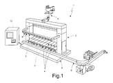
- Number 1 in Figure 1 indicates as a whole an I.S. glassware manufacturing machine comprising a bed 2; a gantry frame 3 extending from bed 2; and a number of forming sections 4 (shown schematically) for forming respective glass articles (not shown) and comprising a number of pneumatic, electric actuating mechanisms and/or servomechanisms.
- each forming section 4 comprises: a respective mold assembly 5 (of a per-se known type, here not described in detail) for successively forming a number of glass articles from respective glass gobs (not shown) supplied by a feed assembly 6 (comprising respective actuating mechanisms); a respective ejector assembly 7 (also comprising respective actuating mechanisms) for expelling the glass articles from the relative mold assembly onto a conveyor 8 for transfer to a furnace (not shown); and an airtight pushbutton panel 9 which, in the example shown, is fitted to frame 3, over bed 2, and enables the operators of I.S. machine 1 to control the machine manually, stopping and/or modifying the production cycles.
- mold assembly 5 comprises at least one rough mold and a finish mold; the rough mold receives a glass gob from feed assembly 6 to form a semifinished glass article, which is rotated by an inverter into the finish mold to blow-mold the finished glass article.
- Ejector assembly 7 in turn comprises a so-called “take-out” element for removing the finished glass article from the finish mold; and a so-called “pusher” element for pushing the glass article onto conveyor 8 (neither the take-out nor the pusher elements are shown in Figure 1 ).
- Each pushbutton panel 9 comprises a number of buttons, and indicator lights indicating particular operating conditions of I.S. machine 1.
- control system 10 (shown schematically), which implements automation of I.S. machine 1 as a whole. More specifically, control system 10 is configured to control and coordinate respective actuators (electric or pneumatic) and servomechanisms of the actuating mechanisms of forming sections 4, and is supplied with status and feedback information from sensors (not shown) on I.S. machine 1, and with operator commands entered from pushbutton panels 9.
- control system 10 comprises a number of automatisms (or functional blocks) 10a-10c, such as: a first automatism 10a for controlling activation of pusher elements in ejector assembly 7 of I.S. machine 1; a second automatism 10b, so-called "timing" automatism, for controlling activation of pneumatic actuating mechanisms of forming sections 4; and a third automatism 10c for controlling activation of electric actuators and/or servomechanisms of forming sections 4.
- automatisms or functional blocks
- Control system 10 comprises: a supervisor unit 12, e.g. provided with an industrial PC and an operator user interface; and a central control unit 14 connected to supervisor unit 12 over a high-speed, two-way, serial data bus, e.g. an Ethernet bus 15.
- a supervisor unit 12 e.g. provided with an industrial PC and an operator user interface
- a central control unit 14 connected to supervisor unit 12 over a high-speed, two-way, serial data bus, e.g. an Ethernet bus 15.
- Supervisor unit 12 e.g. under control of an operator, processes and draws up production plans (so-called "recipes"), and accordingly transmits production data, relative to the processes to be implemented on I.S. machine 1, to central control unit 14 over Ethernet bus 15.
- recipes production plans
- Central control unit 14 receives the production data from supervisor unit 12, and accordingly performs processing operations to determine the exact times at which to activate the actuating mechanisms of automatisms 10a-10c of the whole I.S. machine 1, in order to implement the set production plans.
- central control unit 14 comprises: an interface 14a, adapted to be coupled to Ethernet bus 15 to receive production data from supervisor unit 12; a central processing unit (CPU) 14b, connected to interface 14a, and which performs the processing operations using the received production data to generate commands by which to activate the actuating mechanisms of I.S. machine 1; a memory unit 14c accessible by central processing unit 14b and storing one or more databanks containing information necessary to control automation of I.S. machine 1; and a number of bus controllers 16a-16c, equal in number to automatisms 10a-10c, and operatively coupled to central processing unit 14b.
- CPU central processing unit
- Control system 10 also comprises a number of high-speed fieldbuses 18a-18c equal in number to automatisms 10a-10c and employing, for example, the POWERLINK communication protocol controlled by the "Ethernet POWERLINK Standardization Group".
- Each fieldbus 18a-18c connects central control unit 14 (in particular a relative bus controller 16a-16c) to a respective one of automatism 10a-10c to permit two-way data communication (in particular, transmission of activation commands and reception of feedback and status signals by central control unit 14).
- control system 10 comprises a single processing unit (in particular, central processing unit 14b of central control unit 14) for centralized processing of the production data, to determine the activation timings of the actuating mechanisms of the whole I.S. machine 1.
- Automatisms 10a-10c have no processing capacity, with respect to automation control to perform the production plan, receive respective activation commands from central processing unit 14b, and accordingly command the respective actuating mechanisms.
- control system 10 therefore has a "centralized-intelligence" as opposed to distributed-intelligence architecture. More specifically, the operations performed in forming sections 4 are synchronized by the same centralized processing of the production plan in central control unit 14, so automatisms 10a-10c are not interconnected over a data communications bus.
- Each automatism 10a-10c comprises a bus coupler 19a-19c connectable to respective fieldbus 18a-18c to receive activation commands; and one or more actuating modules connected to respective bus coupler 19a-19c to control and drive the actuators (electric, pneumatic) and/or servomechanisms of the respective actuating mechanisms on the basis of the activation commands received.
- first automatism 10a comprises: a first bus coupler 19a connected to first fieldbus 18a and for controlling data exchange between first automatism 10a and central control unit 14; a number of first input/output I/O modules 20a for controlling data input (in particular, said activation commands) and data output (in particular, feedback and status signals relative to the execution of the activation commands); and a number of first activation modules 21a which, on the basis of the activation commands received, command activation of respective pusher elements (e.g. in a known ramp pattern).
- First activation modules 21a are connected to first input/output modules 20a and to one another over a high-speed, e.g. X2X LINK or CAN OPEN connection.
- Second automatism 10b comprises: a second bus coupler 19b connected to second fieldbus 18b and for controlling data exchange between second automatism 10b and central control unit 14; a number of second input/output I/O modules 20b (including I/O modules for controlling pushbutton panels 9 of forming sections 4); and a number of second activation modules 21b which, on the basis of the activation commands received, command actuators (e.g. proportional valves) of respective pneumatic actuating mechanisms. More specifically, second activation modules 21b are connected to second bus coupler 19b over an auxiliary bus 22, e.g. a high-speed POWERLINK protocol bus, to which they are coupled by respective auxiliary interfaces 23.
- auxiliary bus 22 e.g. a high-speed POWERLINK protocol bus
- third automatism 10c comprises: a third bus coupler 19c connected to third fieldbus 18c and for controlling data exchange between third automatism 10c and central control unit 14; a number of third input/output I/O modules 20c; one or more power modules 23, and a number of third activation modules 21c, which, on the basis of the activation commands received, command electric motors (e.g. direct-current or step motors) and/or servomechanisms of forming sections 4 of I.S. machine 1.
- Third activation modules 21c and power modules 23 are connected to third input/output modules 20c and to one another by an extension 24 of fieldbus 18c, operating at high-speed with the POWERLINK protocol.
- third activation modules 21c and power modules 23 can be divided into one or more groups, with which are associated respective third input/output I/O modules 20c connected to extension 24 of fieldbus 18c by a respective interface 25.
- the main advantage of the I.S. glassware molding machine 1 and control system as described above is that of solving the timing and data communication problems of known machines.
- automation operations consisting in processing the production plan and determining the activation times of the various actuating mechanisms
- a single central processing unit 14b which generates corresponding activation commands for the various automatisms 10a-10c of I.S. machine 1 as a whole.
- No data communication between automatisms 10a-10c is therefore required to coordinate and synchronize them, and the same automatisms 10a-10c have no independent intelligence as regards automation control.
- respective fieldbuses 18a-18c only exchange between central control unit 14 and automatisms 10a-10c data and signals relating to the execution of the activation commands, while no data are exchanged relating to automation control and management.
- Control system 10 is improved as regards automation control processing power and resources; data storage resources are concentrated in a single central control unit 14, with no wasteful duplication within the various automatisms 10a-10c.
- Control system 10 is therefore cheaper and easier to implement and maintain, and is faster (by involving no data communication problems between the various automatisms).
- control system 10 is intended purely as a non-limiting example, and the functional subdivision of control system 10 may differ.
- further automatisms 10c' may be provided to control activation of the electric motors and servomechanisms (e.g. an automatism for each of forming sections 4); the further automatisms 10c' also have no processing capacity in terms of automation control.
Landscapes
- Physics & Mathematics (AREA)
- General Physics & Mathematics (AREA)
- Engineering & Computer Science (AREA)
- Automation & Control Theory (AREA)
- Programmable Controllers (AREA)
- Manufacture, Treatment Of Glass Fibers (AREA)
- Glass Compositions (AREA)
- Re-Forming, After-Treatment, Cutting And Transporting Of Glass Products (AREA)
Applications Claiming Priority (1)
| Application Number | Priority Date | Filing Date | Title |
|---|---|---|---|
| IT000235A ITTO20080235A1 (it) | 2008-03-27 | 2008-03-27 | Sistema di controllo di una macchina di formatura di articoli di vetro |
Publications (2)
| Publication Number | Publication Date |
|---|---|
| EP2105812A2 true EP2105812A2 (de) | 2009-09-30 |
| EP2105812A3 EP2105812A3 (de) | 2010-12-22 |
Family
ID=40293299
Family Applications (1)
| Application Number | Title | Priority Date | Filing Date |
|---|---|---|---|
| EP09156209A Ceased EP2105812A3 (de) | 2008-03-27 | 2009-03-25 | Steuerungssystem für Glaswarenformmaschine |
Country Status (3)
| Country | Link |
|---|---|
| US (1) | US20090255296A1 (de) |
| EP (1) | EP2105812A3 (de) |
| IT (1) | ITTO20080235A1 (de) |
Families Citing this family (2)
| Publication number | Priority date | Publication date | Assignee | Title |
|---|---|---|---|---|
| US11912608B2 (en) | 2019-10-01 | 2024-02-27 | Owens-Brockway Glass Container Inc. | Glass manufacturing |
| CN117940383A (zh) * | 2021-09-30 | 2024-04-26 | 欧文斯-布洛克威玻璃容器有限公司 | 熔融玻璃运输系统 |
Citations (2)
| Publication number | Priority date | Publication date | Assignee | Title |
|---|---|---|---|---|
| EP0990966A2 (de) * | 1998-10-04 | 2000-04-05 | Husky Injection Molding Systems Ltd. | Integrierte Steuerungsstation für eine Spritzgussanlage |
| EP1537052B1 (de) | 2002-09-03 | 2006-05-03 | Owens-Brockway Glass Container Inc. | Kontrolleinrichtung einer glasformungsmaschine |
Family Cites Families (2)
| Publication number | Priority date | Publication date | Assignee | Title |
|---|---|---|---|---|
| DE10140271A1 (de) * | 2001-08-16 | 2003-03-06 | Hermann Heye I I | Elektronische Steuerung für Glasformmaschinen |
| DE60234828D1 (de) * | 2002-09-03 | 2010-02-04 | Futronic Gmbh | Modulares Steuerungssystem für eine Glasformmaschine |
-
2008
- 2008-03-27 IT IT000235A patent/ITTO20080235A1/it unknown
-
2009
- 2009-03-25 EP EP09156209A patent/EP2105812A3/de not_active Ceased
- 2009-03-26 US US12/383,730 patent/US20090255296A1/en not_active Abandoned
Patent Citations (2)
| Publication number | Priority date | Publication date | Assignee | Title |
|---|---|---|---|---|
| EP0990966A2 (de) * | 1998-10-04 | 2000-04-05 | Husky Injection Molding Systems Ltd. | Integrierte Steuerungsstation für eine Spritzgussanlage |
| EP1537052B1 (de) | 2002-09-03 | 2006-05-03 | Owens-Brockway Glass Container Inc. | Kontrolleinrichtung einer glasformungsmaschine |
Also Published As
| Publication number | Publication date |
|---|---|
| ITTO20080235A1 (it) | 2009-09-28 |
| EP2105812A3 (de) | 2010-12-22 |
| US20090255296A1 (en) | 2009-10-15 |
Similar Documents
| Publication | Publication Date | Title |
|---|---|---|
| EP0603011B1 (de) | Steuerung einer Maschine zum Herstellen von Glascontainern | |
| CN108908851A (zh) | 注塑机的电射台伺服系统及其数据交互流程 | |
| CN107024902B (zh) | 通过公共语言规格的程序驱动多种生产装置的生产系统 | |
| CN105195655A (zh) | 工业机器人锻造自动线系统及其控制方法 | |
| CN106495438A (zh) | 机电一体玻璃器皿成型生产线生产工艺及控制方法 | |
| CN205540224U (zh) | 冲床机械手的控制系统 | |
| US7054710B2 (en) | Electronic control for glass moulding machines | |
| CZ295575B6 (cs) | Způsob pro ovládání pohybů zakládače tunelové chladicí pece a způsob řízení pohybů zasouvací tyče zakládače | |
| EP2105812A2 (de) | Steuerungssystem für Glaswarenformmaschine | |
| CN105668256A (zh) | 混凝土预制板生产线的养护房码垛车控制系统及控制方法 | |
| US20020052669A1 (en) | Control system for a machine for producing hollow glass articles | |
| EP1537052B1 (de) | Kontrolleinrichtung einer glasformungsmaschine | |
| EP3034475B1 (de) | Steuerungseinheit für i.s. typ-maschine | |
| TWI542512B (zh) | 多軸控制裝置、循圓方法以及包裝機 | |
| CN204913925U (zh) | 冲床上下料机器人控制装置 | |
| CN111522313B (zh) | 一种基于canopen协议控制伺服电机曲线运动的方法 | |
| EP0351437B1 (de) | Cnc-regelungssystem | |
| CN107272614A (zh) | 一种教学加工型智能制造集成装置的控制系统 | |
| US7139634B2 (en) | Device and method for controlling a glass forming machine | |
| CN201408354Y (zh) | 一种整合精密加工机械与机械手臂的控制装置 | |
| EP4161755B1 (de) | Verfahren und vorrichtung zur formsteuerung | |
| KR101262831B1 (ko) | 프레스 라인용 연속운전 시스템 | |
| US20050253547A1 (en) | Integrated system for controlling axes of industrial machinery | |
| CN205620788U (zh) | 一种自动控制系统 | |
| EP1216966B1 (de) | Verfahren zum einstellen von betriebsmassnahmen bei der herstellung von hohlglaswaren |
Legal Events
| Date | Code | Title | Description |
|---|---|---|---|
| PUAI | Public reference made under article 153(3) epc to a published international application that has entered the european phase |
Free format text: ORIGINAL CODE: 0009012 |
|
| AK | Designated contracting states |
Kind code of ref document: A2 Designated state(s): AT BE BG CH CY CZ DE DK EE ES FI FR GB GR HR HU IE IS IT LI LT LU LV MC MK MT NL NO PL PT RO SE SI SK TR |
|
| AX | Request for extension of the european patent |
Extension state: AL BA RS |
|
| PUAL | Search report despatched |
Free format text: ORIGINAL CODE: 0009013 |
|
| AK | Designated contracting states |
Kind code of ref document: A3 Designated state(s): AT BE BG CH CY CZ DE DK EE ES FI FR GB GR HR HU IE IS IT LI LT LU LV MC MK MT NL NO PL PT RO SE SI SK TR |
|
| AX | Request for extension of the european patent |
Extension state: AL BA RS |
|
| 17P | Request for examination filed |
Effective date: 20110622 |
|
| 17Q | First examination report despatched |
Effective date: 20110801 |
|
| AKX | Designation fees paid |
Designated state(s): AT BE BG CH CY CZ DE DK EE ES FI FR GB GR HR HU IE IS IT LI LT LU LV MC MK MT NL NO PL PT RO SE SI SK TR |
|
| STAA | Information on the status of an ep patent application or granted ep patent |
Free format text: STATUS: THE APPLICATION HAS BEEN REFUSED |
|
| 18R | Application refused |
Effective date: 20120608 |