EP2105995A1 - Dispositif amélioré de connexion, méthode et groupe électrique de raccordement correspondants - Google Patents
Dispositif amélioré de connexion, méthode et groupe électrique de raccordement correspondants Download PDFInfo
- Publication number
- EP2105995A1 EP2105995A1 EP09155268A EP09155268A EP2105995A1 EP 2105995 A1 EP2105995 A1 EP 2105995A1 EP 09155268 A EP09155268 A EP 09155268A EP 09155268 A EP09155268 A EP 09155268A EP 2105995 A1 EP2105995 A1 EP 2105995A1
- Authority
- EP
- European Patent Office
- Prior art keywords
- connector device
- bars
- electrical connection
- hole
- group
- Prior art date
- Legal status (The legal status is an assumption and is not a legal conclusion. Google has not performed a legal analysis and makes no representation as to the accuracy of the status listed.)
- Withdrawn
Links
- 238000000034 method Methods 0.000 title claims description 13
- 239000004020 conductor Substances 0.000 claims abstract description 12
- ATJFFYVFTNAWJD-UHFFFAOYSA-N Tin Chemical compound [Sn] ATJFFYVFTNAWJD-UHFFFAOYSA-N 0.000 claims description 8
- 239000011248 coating agent Substances 0.000 claims description 4
- 238000000576 coating method Methods 0.000 claims description 4
- RYGMFSIKBFXOCR-UHFFFAOYSA-N Copper Chemical compound [Cu] RYGMFSIKBFXOCR-UHFFFAOYSA-N 0.000 claims description 3
- 229910052802 copper Inorganic materials 0.000 claims description 3
- 239000010949 copper Substances 0.000 claims description 3
- 239000002184 metal Substances 0.000 claims description 2
- 229910052751 metal Inorganic materials 0.000 claims description 2
- 230000003647 oxidation Effects 0.000 claims description 2
- 238000007254 oxidation reaction Methods 0.000 claims description 2
- 230000001681 protective effect Effects 0.000 claims description 2
- 238000007493 shaping process Methods 0.000 claims description 2
- 239000011295 pitch Substances 0.000 description 6
- 238000006243 chemical reaction Methods 0.000 description 2
- 238000003780 insertion Methods 0.000 description 2
- 230000037431 insertion Effects 0.000 description 2
- 238000000926 separation method Methods 0.000 description 2
- 230000003313 weakening effect Effects 0.000 description 2
- 239000000956 alloy Substances 0.000 description 1
- 229910045601 alloy Inorganic materials 0.000 description 1
- 230000005540 biological transmission Effects 0.000 description 1
- 230000001419 dependent effect Effects 0.000 description 1
- 230000001939 inductive effect Effects 0.000 description 1
- 238000009434 installation Methods 0.000 description 1
- 239000000463 material Substances 0.000 description 1
- 238000012986 modification Methods 0.000 description 1
- 230000004048 modification Effects 0.000 description 1
- 230000002093 peripheral effect Effects 0.000 description 1
- 239000011253 protective coating Substances 0.000 description 1
Images





Classifications
-
- H—ELECTRICITY
- H01—ELECTRIC ELEMENTS
- H01R—ELECTRICALLY-CONDUCTIVE CONNECTIONS; STRUCTURAL ASSOCIATIONS OF A PLURALITY OF MUTUALLY-INSULATED ELECTRICAL CONNECTING ELEMENTS; COUPLING DEVICES; CURRENT COLLECTORS
- H01R9/00—Structural associations of a plurality of mutually-insulated electrical connecting elements, e.g. terminal strips or terminal blocks; Terminals or binding posts mounted upon a base or in a case; Bases therefor
- H01R9/22—Bases, e.g. strip, block, panel
- H01R9/24—Terminal blocks
- H01R9/26—Clip-on terminal blocks for side-by-side rail- or strip-mounting
-
- H—ELECTRICITY
- H01—ELECTRIC ELEMENTS
- H01R—ELECTRICALLY-CONDUCTIVE CONNECTIONS; STRUCTURAL ASSOCIATIONS OF A PLURALITY OF MUTUALLY-INSULATED ELECTRICAL CONNECTING ELEMENTS; COUPLING DEVICES; CURRENT COLLECTORS
- H01R13/00—Details of coupling devices of the kinds covered by groups H01R12/70 or H01R24/00 - H01R33/00
- H01R13/02—Contact members
- H01R13/04—Pins or blades for co-operation with sockets
- H01R13/05—Resilient pins or blades
-
- H—ELECTRICITY
- H01—ELECTRIC ELEMENTS
- H01R—ELECTRICALLY-CONDUCTIVE CONNECTIONS; STRUCTURAL ASSOCIATIONS OF A PLURALITY OF MUTUALLY-INSULATED ELECTRICAL CONNECTING ELEMENTS; COUPLING DEVICES; CURRENT COLLECTORS
- H01R43/00—Apparatus or processes specially adapted for manufacturing, assembling, maintaining, or repairing of line connectors or current collectors or for joining electric conductors
- H01R43/16—Apparatus or processes specially adapted for manufacturing, assembling, maintaining, or repairing of line connectors or current collectors or for joining electric conductors for manufacturing contact members, e.g. by punching and by bending
-
- H—ELECTRICITY
- H01—ELECTRIC ELEMENTS
- H01R—ELECTRICALLY-CONDUCTIVE CONNECTIONS; STRUCTURAL ASSOCIATIONS OF A PLURALITY OF MUTUALLY-INSULATED ELECTRICAL CONNECTING ELEMENTS; COUPLING DEVICES; CURRENT COLLECTORS
- H01R9/00—Structural associations of a plurality of mutually-insulated electrical connecting elements, e.g. terminal strips or terminal blocks; Terminals or binding posts mounted upon a base or in a case; Bases therefor
- H01R9/22—Bases, e.g. strip, block, panel
- H01R9/24—Terminal blocks
- H01R9/26—Clip-on terminal blocks for side-by-side rail- or strip-mounting
- H01R9/2675—Electrical interconnections between two blocks, e.g. by means of busbars
-
- H—ELECTRICITY
- H01—ELECTRIC ELEMENTS
- H01R—ELECTRICALLY-CONDUCTIVE CONNECTIONS; STRUCTURAL ASSOCIATIONS OF A PLURALITY OF MUTUALLY-INSULATED ELECTRICAL CONNECTING ELEMENTS; COUPLING DEVICES; CURRENT COLLECTORS
- H01R13/00—Details of coupling devices of the kinds covered by groups H01R12/70 or H01R24/00 - H01R33/00
- H01R13/02—Contact members
- H01R13/03—Contact members characterised by the material, e.g. plating, or coating materials
Definitions
- the present invention refers to an improved connector device for electrical connection of electrical panel terminals, a method for obtaining such connector device, an electrical connection group provided with such improved connector device and an improved connector group comprising a plurality of improved connector devices.
- the abovementioned invention regards making removable electrical groups and connections suitable for transverse connections in a terminal board, typically for electrical panels for power distribution.
- electrical panels for power distribution comprise a plurality of pairs of modular terminals arranged adjacent to each other and provided with connection units for the appliances served by the panel itself.
- Each respective pair of terminals is generally made up of conductor bodies usually contained in insulating bodies, and narrow inlet and outlet spaces for the electrical connections.
- each pair of terminals is achieved by connecting two conductor bodies, generally a perforated plate accommodated in a first terminal and a rod element projecting from the second terminal which, during use, is inside the abovementioned hole to attain the passage of current between the related terminals.
- Such connections must ensure a stable and efficient electrical contact, with shape constraints between holes and the relative rods which, cooperating with each other, must stably maintain a relative contact to ensure both the proper assembling position of the pair of terminals and an efficient electrical conduction.
- both the perforated plate and the relative rod elements are independent from each other but made in a single piece passing transversely through all the pairs of terminals ending up forming the so-called "parallel bridges".
- An object of the present invention is that of providing a device capable of overcoming the abovementioned drawbacks of the prior art in an extremely simple, inexpensive and particularly functional manner.
- Another object is that of obtaining an improved connector device for electrical connection between electrical terminals capable of guaranteeing a firm assembling position for the relative pair of terminals as well as an efficient electrical conduction between the terminals themselves.
- Another object is that of obtaining an improved connector device for electrical connection between electrical terminals smaller in size and with a structure having a high elasticity.
- Another object is that of obtaining an improved connector group, or a "parallel bridge", comprising a plurality of improved connector devices subject of the present invention capable of overcoming the drawbacks regarding connections of groups of parallel terminals of the prior art i.e. independent from the number of pitches of the electrical panel to be connected and allowing an easy, stable and efficient installation of the electrical panel itself.
- Another object is that of providing a quick and efficient method for obtaining the connector device subject of the present invention.
- Another object is that of obtaining an electrical connection group, or electrical panel, provided with at least one connector device subject of the present invention.
- reference number 10 indicates an improved connector device for the electrical connection between electrical terminals
- reference number 100 indicates an electrical connection group provided with such improved connector device 10
- reference number 102 indicates an electrical panel provided with an improved connector group 101 comprising a plurality of improved connector devices 10 in parallel.
- the abovementioned improved connector device 10 of the present invention in particular suitable to establish the conduction continuity between two different terminals 11, 11' of an electrical panel, is shown according to a preferred embodiment in figure 1 and it is obtained from a band 20 made of electrically conducting material, generally a high copper content alloy.
- Such connector device 10 substantially develops in longitudinal direction and comprises a first 12 and a second 13 end which are substantially located at the same level.
- the connector device 10 comprises a central portion 14 provided with a three dimensional and highly elastic structure.
- Such high elasticity directly derives from the same geometry of the central portion 14 which is provided according to the invention with at least three thin bars 15, 15', 15" which start from the first end 12 and meet in the second end 13.
- the geometry of the central portion 14 confers the connector device 10 a high elasticity which, advantageously, allows using highly conductive materials as well as reducing the dimension of the connector device 10 itself without jeopardising the overall elasticity of the object of the present invention.
- the connector device 10 may be obtained from a high copper content metal section coated with tin on the two opposite faces.
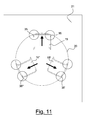
- the three bars 15, 15', 15" of the connector device 10 may comprise a substantially square-shaped or parallelepiped section in which the external edges 35, as observable in figure 10 and 11 , have a rounded shape and are protected by a tin coating, in such a manner to prevent the oxidation of the contact point and have a greater electrical transmission efficiency.
- the method according to the present invention for the making of a connector device 10 as described previously solely comprises the steps of cutting and cold deformation of a band 20 of electrically conducting material.
- the abovementioned knives/punches 60, 60', 62, 62', 61 advantageously perform a plastic dragging of the protective tin layers on the turned in part of the cutting surface, as shown for example in figure 10 .
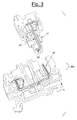
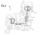
- the connector device 10 is particularly advantageous for the electrical connection of said two terminals 11, 11' to obtain an electrical connection group 100 of the type shown in figures 3 and 4 .
- Such electrical connection group 100 comprises at least one first and one second terminal 11, 11' to be electrically connected and at least one connector device 10, as described previously, which electrically connects the abovementioned two terminals 11, 11'.
- the first end 12 of the connector device 10 is constrained in a substantially non-accessible manner inside the first terminal 11 while the second end 13 is accessible and extended outwards from the first terminal 11 itself.
- each bar 15, 15', 15" is in contact with the hole 20.
- the hole 20 is an end of an element 21 made of electrically conducting material arranged at least partially inside the second terminal 11'.
- the hole 20 is preferably circular-shaped and the distance - when idle - between the opposite peripheral edges of the three bars 15, 15', 15" exceeds the value of the diameter of the hole 20 in the range of 0.1-1 mm.
- the abovementioned “interference” range may also vary between 0.2-0.4 mm.
- the three bars 15, 15', 15" which form the central portion 14 have the external edges 35 lying, when idle, at a mutual distance greater than the diameter of the hole 20 which is to receive the three bars 15, 15', 15" themselves.
- the bars 15, 15', 15" are thus elastically deformed and exert three reaction forces in direction opposite to the forced approaching of the bars themselves.
- constriction forces of the bars 15, 15', 15" are directed according to the contact diameter, identical and opposite to the reaction forces of the bars, thus ensuring contact.
- the circular shape of the hole 20 is preferred since it is capable of ensuring that the insertion of the three bars 15, 15', 15" occurs with a deformation that is constant and independent from the orientation of the three bars 15, 15', 15" themselves with respect to the axis of the hole.
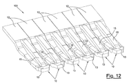
- an improved connector group 101 or "parallel bridge", comprising a plurality of connector devices 10 parallel to each other.
- this improved connector group 101 shown in figures 12 and 13 during different steps of use, comprises a common first end 12 from which a plurality of said central portions 14 ending in relative second ends 13 develop parallel to each other.
- Such improved connector group 101 allows connecting a plurality of electrical connection groups 100 to obtain an electrical panel 102 independently from the number of pitches separating the terminals to be used of the electrical panel 102 itself.
- the common first end 12 provided for can be weakening grooves which facilitate the separation of some devices 10 to prepare the parallel bridges of the desired pitch as observable in the example of figure 13 .
- the connector device 10 as described previously comprises a first 12 and a second 13 end substantially arranged at the same level and a central portion 14 between such ends 12, 13 comprising a three dimensional and elastic structure provided with at least three thin bars 15, 15', 15" that start from the first end 12 and meet in the second end 13.
- the connector device 10 of the present invention allows obtaining an improved connector group, or "parallel bridges", comprising a plurality of devices 10, independently from the number of pitches separating the various terminals in use in an electrical panel.
- provided for at the common first end 12 can be weakening grooves which facilitate the separation of some devices 10 to prepare parallel bridges of the desired pitch.
- an improved connector device for electrical connection between electrical terminals a method for obtaining such connector device, an electrical connection group provided with such improved connector device and an improved connector group comprising a plurality of improved connector devices according to the present invention attain the objects outlined previously.
- the improved connector device for electrical connection between electrical terminals the method for obtaining such connector device, the electrical connection group provided with such improved connector device and the improved connector group comprising a plurality of improved connector devices of the present invention thus conceived are susceptible to numerous modifications and variants, all falling within the same inventive concept; furthermore, all details can be replaced by technically equivalent elements.
- the materials used, as well as dimensions thereof and the protective coating may vary depending on the technical requirements.
Landscapes
- Engineering & Computer Science (AREA)
- Manufacturing & Machinery (AREA)
- Coupling Device And Connection With Printed Circuit (AREA)
- Connections Effected By Soldering, Adhesion, Or Permanent Deformation (AREA)
Applications Claiming Priority (1)
| Application Number | Priority Date | Filing Date | Title |
|---|---|---|---|
| ITMI20080513 ITMI20080513A1 (it) | 2008-03-27 | 2008-03-27 | Dispositivo connettore perfezionato per il collegamento elettrico tra morsetti elettrici, metodo per la realizzazione di tale dispositivo connettore e gruppo di collegamento elettrico dotato di tale dispositivo connettore perfezionato |
Publications (1)
| Publication Number | Publication Date |
|---|---|
| EP2105995A1 true EP2105995A1 (fr) | 2009-09-30 |
Family
ID=40292968
Family Applications (1)
| Application Number | Title | Priority Date | Filing Date |
|---|---|---|---|
| EP09155268A Withdrawn EP2105995A1 (fr) | 2008-03-27 | 2009-03-16 | Dispositif amélioré de connexion, méthode et groupe électrique de raccordement correspondants |
Country Status (2)
| Country | Link |
|---|---|
| EP (1) | EP2105995A1 (fr) |
| IT (1) | ITMI20080513A1 (fr) |
Cited By (7)
| Publication number | Priority date | Publication date | Assignee | Title |
|---|---|---|---|---|
| DE102010037846A1 (de) * | 2010-09-29 | 2012-03-29 | Phoenix Contact Gmbh & Co. Kg | Stockwerksbrücker |
| EP2579393A1 (fr) * | 2011-10-06 | 2013-04-10 | Tyco Electronics Belgium EC BVBA | Ensemble formant connexion électrique |
| JP2013161672A (ja) * | 2012-02-06 | 2013-08-19 | Toyo Giken Kk | 端子台分離器、及び集合端子台装置 |
| US9356367B2 (en) | 2014-01-08 | 2016-05-31 | Tyco Electronics Corporation | Electrical connector having compliant contacts and a circuit board assembly including the same |
| EP3588682A1 (fr) * | 2018-06-22 | 2020-01-01 | Würth Elektronik Eisos Gmbh & CO. KG | Contact pour raccord enfichable direct et raccord enfichable direct |
| DE102019131175A1 (de) * | 2019-11-19 | 2021-05-20 | Kiekert Aktiengesellschaft | Kraftfahrzeugtechnischer Komponententräger für elektrische/elektronische Bauteile |
| US12399196B2 (en) | 2019-08-29 | 2025-08-26 | Solaredge Technologies Ltd. | Terminal sensor array |
Families Citing this family (1)
| Publication number | Priority date | Publication date | Assignee | Title |
|---|---|---|---|---|
| CN106207531B (zh) * | 2016-06-21 | 2018-08-24 | 上海沪工汽车电器有限公司 | 免焊pcb式音叉端子及其安装方法 |
Citations (11)
| Publication number | Priority date | Publication date | Assignee | Title |
|---|---|---|---|---|
| EP0088018A1 (fr) * | 1982-03-01 | 1983-09-07 | The Bendix Corporation | Une méthode de fabrication d'un contact électrique de deux pièces pour usage dans un connecteur électrique |
| EP0225400A1 (fr) * | 1985-12-11 | 1987-06-16 | Burndy Electra N.V. | Broche de contact |
| US4906209A (en) * | 1987-10-01 | 1990-03-06 | Murata Manufacturing Co., Ltd. | Feed-through capacitor having a compliant pin terminal |
| EP0784355A1 (fr) * | 1996-01-10 | 1997-07-16 | Entrelec Sa | Agencement d'interconnexion pour appareillage électrique, notamment pour appareillage de type bloc de jonction, et boîtier équipé d'une tel agencement |
| US5669788A (en) * | 1996-09-18 | 1997-09-23 | Allen-Bradley Company, Inc. | Screwless terminal block linking apparatus |
| US5944538A (en) * | 1995-03-08 | 1999-08-31 | Leopold Kostal Gmbh & Co. Kg. | Pin shaped contact element |
| US6286209B1 (en) * | 1995-12-01 | 2001-09-11 | Berg Technology, Inc. | Method of making smooth contact terminals |
| US20010055697A1 (en) * | 2000-05-20 | 2001-12-27 | Stolberger Metallwerke Gmbh & Co Kg | Electrically conductive metal tape and plug connector made of it |
| US20050239345A1 (en) * | 2004-04-23 | 2005-10-27 | Yazaki Corporation | Circuit board connector terminal |
| WO2006126624A1 (fr) * | 2005-05-26 | 2006-11-30 | Alps Electric Co., Ltd. | Borne de connexion et composant électrique l’utilisant |
| EP1788585A1 (fr) * | 2004-09-10 | 2007-05-23 | Kabushiki Kaisha Kobe Seiko Sho (Kobe Steel, Ltd.) | Matériau conducteur pour pièce de connexion et procédé de fabrication du matériau conducteur |
-
2008
- 2008-03-27 IT ITMI20080513 patent/ITMI20080513A1/it unknown
-
2009
- 2009-03-16 EP EP09155268A patent/EP2105995A1/fr not_active Withdrawn
Patent Citations (11)
| Publication number | Priority date | Publication date | Assignee | Title |
|---|---|---|---|---|
| EP0088018A1 (fr) * | 1982-03-01 | 1983-09-07 | The Bendix Corporation | Une méthode de fabrication d'un contact électrique de deux pièces pour usage dans un connecteur électrique |
| EP0225400A1 (fr) * | 1985-12-11 | 1987-06-16 | Burndy Electra N.V. | Broche de contact |
| US4906209A (en) * | 1987-10-01 | 1990-03-06 | Murata Manufacturing Co., Ltd. | Feed-through capacitor having a compliant pin terminal |
| US5944538A (en) * | 1995-03-08 | 1999-08-31 | Leopold Kostal Gmbh & Co. Kg. | Pin shaped contact element |
| US6286209B1 (en) * | 1995-12-01 | 2001-09-11 | Berg Technology, Inc. | Method of making smooth contact terminals |
| EP0784355A1 (fr) * | 1996-01-10 | 1997-07-16 | Entrelec Sa | Agencement d'interconnexion pour appareillage électrique, notamment pour appareillage de type bloc de jonction, et boîtier équipé d'une tel agencement |
| US5669788A (en) * | 1996-09-18 | 1997-09-23 | Allen-Bradley Company, Inc. | Screwless terminal block linking apparatus |
| US20010055697A1 (en) * | 2000-05-20 | 2001-12-27 | Stolberger Metallwerke Gmbh & Co Kg | Electrically conductive metal tape and plug connector made of it |
| US20050239345A1 (en) * | 2004-04-23 | 2005-10-27 | Yazaki Corporation | Circuit board connector terminal |
| EP1788585A1 (fr) * | 2004-09-10 | 2007-05-23 | Kabushiki Kaisha Kobe Seiko Sho (Kobe Steel, Ltd.) | Matériau conducteur pour pièce de connexion et procédé de fabrication du matériau conducteur |
| WO2006126624A1 (fr) * | 2005-05-26 | 2006-11-30 | Alps Electric Co., Ltd. | Borne de connexion et composant électrique l’utilisant |
Cited By (10)
| Publication number | Priority date | Publication date | Assignee | Title |
|---|---|---|---|---|
| DE102010037846A1 (de) * | 2010-09-29 | 2012-03-29 | Phoenix Contact Gmbh & Co. Kg | Stockwerksbrücker |
| EP2579393A1 (fr) * | 2011-10-06 | 2013-04-10 | Tyco Electronics Belgium EC BVBA | Ensemble formant connexion électrique |
| EP2658036A1 (fr) * | 2011-10-06 | 2013-10-30 | Tyco Electronics Belgium EC BVBA | Ensemble formant connexion électrique |
| JP2013161672A (ja) * | 2012-02-06 | 2013-08-19 | Toyo Giken Kk | 端子台分離器、及び集合端子台装置 |
| US9356367B2 (en) | 2014-01-08 | 2016-05-31 | Tyco Electronics Corporation | Electrical connector having compliant contacts and a circuit board assembly including the same |
| EP3588682A1 (fr) * | 2018-06-22 | 2020-01-01 | Würth Elektronik Eisos Gmbh & CO. KG | Contact pour raccord enfichable direct et raccord enfichable direct |
| US10797415B2 (en) | 2018-06-22 | 2020-10-06 | Würth Elektronik eiSos Gmbh & Co. KG | Contact for a direct plug-in connection, and direct plug-in connection |
| US12399196B2 (en) | 2019-08-29 | 2025-08-26 | Solaredge Technologies Ltd. | Terminal sensor array |
| DE102019131175A1 (de) * | 2019-11-19 | 2021-05-20 | Kiekert Aktiengesellschaft | Kraftfahrzeugtechnischer Komponententräger für elektrische/elektronische Bauteile |
| WO2021098911A1 (fr) * | 2019-11-19 | 2021-05-27 | Kiekert Ag | Support de composant pour composants électriques/électroniques à utiliser en ingénierie automobile |
Also Published As
| Publication number | Publication date |
|---|---|
| ITMI20080513A1 (it) | 2009-09-28 |
Similar Documents
| Publication | Publication Date | Title |
|---|---|---|
| EP2105995A1 (fr) | Dispositif amélioré de connexion, méthode et groupe électrique de raccordement correspondants | |
| US9466893B2 (en) | Single element wire to board connector | |
| US8721376B1 (en) | Single element wire to board connector | |
| JP6099769B2 (ja) | ソケットコンタクト | |
| US10085340B2 (en) | Flat circuit body with terminal and manufacturing method thereof | |
| DK164618B (da) | Indretning til etablering af en lodde-, skrue- og afisoleringsfri dobbeltkontakt eller multikontakt paa et tilslutningselement | |
| EP2546931A1 (fr) | Structure de connexion à conducteur en aluminium et connecteur | |
| JPWO2009101965A1 (ja) | 端子金具及びワイヤーハーネス | |
| EP1930988A2 (fr) | Fixation de câble, ensemble câble la comprenant et connecteur comprenant la fixation | |
| JP2013004453A (ja) | 雌端子 | |
| US20160322733A1 (en) | Caged poke home contact | |
| RU2449442C2 (ru) | Устройство транспозиции для предварительно изготовленной системы электрических каналов | |
| JP2010061870A (ja) | 端子金具及び端子金具付き電線 | |
| US20120264337A1 (en) | Cable Connector | |
| JP2010027464A (ja) | 端子金具及び端子金具付き電線 | |
| EP2924808A1 (fr) | Connecteur pour la connexion électrique d'une pluralité de lignes de signaux | |
| JP2005302481A (ja) | コネクタ | |
| US10804634B2 (en) | Electronic contact | |
| EP3599675B1 (fr) | Barre de bus et procédé de fabrication d'une barre de bus | |
| JP5813488B2 (ja) | コネクタの製造方法 | |
| US9614298B2 (en) | Crimp terminal | |
| CA2145581C (fr) | Faisceau de cables electriques | |
| KR20090034786A (ko) | 교차 전도체 | |
| EP2284860A3 (fr) | Résistance électrique et commutateur d'installation doté d'une résistance électrique | |
| JP5622051B2 (ja) | 基板用端子およびそれを用いた基板用コネクタ |
Legal Events
| Date | Code | Title | Description |
|---|---|---|---|
| PUAI | Public reference made under article 153(3) epc to a published international application that has entered the european phase |
Free format text: ORIGINAL CODE: 0009012 |
|
| AK | Designated contracting states |
Kind code of ref document: A1 Designated state(s): AT BE BG CH CY CZ DE DK EE ES FI FR GB GR HR HU IE IS IT LI LT LU LV MC MK MT NL NO PL PT RO SE SI SK TR |
|
| AX | Request for extension of the european patent |
Extension state: AL BA RS |
|
| 17P | Request for examination filed |
Effective date: 20100329 |
|
| AKX | Designation fees paid |
Designated state(s): AT BE BG CH CY CZ DE DK EE ES FI FR GB GR HR HU IE IS IT LI LT LU LV MC MK MT NL NO PL PT RO SE SI SK TR |
|
| 17Q | First examination report despatched |
Effective date: 20100902 |
|
| STAA | Information on the status of an ep patent application or granted ep patent |
Free format text: STATUS: THE APPLICATION IS DEEMED TO BE WITHDRAWN |
|
| 18D | Application deemed to be withdrawn |
Effective date: 20110113 |