EP2106005B1 - Unité d'alimentation pour application sous plancher - Google Patents
Unité d'alimentation pour application sous plancher Download PDFInfo
- Publication number
- EP2106005B1 EP2106005B1 EP09003998.3A EP09003998A EP2106005B1 EP 2106005 B1 EP2106005 B1 EP 2106005B1 EP 09003998 A EP09003998 A EP 09003998A EP 2106005 B1 EP2106005 B1 EP 2106005B1
- Authority
- EP
- European Patent Office
- Prior art keywords
- frame
- latching
- supply unit
- additional
- unit according
- Prior art date
- Legal status (The legal status is an assumption and is not a legal conclusion. Google has not performed a legal analysis and makes no representation as to the accuracy of the status listed.)
- Not-in-force
Links
Images


Classifications
-
- H—ELECTRICITY
- H02—GENERATION; CONVERSION OR DISTRIBUTION OF ELECTRIC POWER
- H02G—INSTALLATION OF ELECTRIC CABLES OR LINES, OR OF COMBINED OPTICAL AND ELECTRIC CABLES OR LINES
- H02G3/00—Installations of electric cables or lines or protective tubing therefor in or on buildings, equivalent structures or vehicles
- H02G3/02—Details
- H02G3/08—Distribution boxes; Connection or junction boxes
- H02G3/18—Distribution boxes; Connection or junction boxes providing line outlets
- H02G3/185—Floor outlets and access cups
Definitions
- the invention relates to a supply unit for underfloor applications, which are provided with a latching conductor frame, which is equipped with at least one row of slots on two opposite sides, wherein on the latching conductor device cup can be fixed in different insertion depths.
- the EP1.811.624 shows a two-part supply unit for underfloor applications, both parts are adjustable in the total installation height.
- the upper part of the supply unit has rows of slots, which are provided for the attachment of built-in appliances (switches, sockets, etc.).
- the lower part of the supply unit is connected by screws to the upper part and adjusted in height
- the object of the invention is to develop a device cup mounting, which allows attachment of the device cup deviating from the standard depth in a desired depth in a simple manner, the provision of different insertion depths by an assembly with little expenditure of time should be possible.
- a latching conductor frame is provided on a supply unit for underfloor applications.
- the latching conductor frame has at least one row of slots on two opposite sides, preferably three pairs of rows of slots are provided, so that three device cups can be inserted in different slots of the row of slots and thus detachably fastened in different insertion depths.
- This integrated in the supply unit snap-in frame shows, as in known device cup recordings slot rows that allow Einsetziefen for device cup gradually up to 30 mm.
- At least one additional frame is provided as a locking conductor extension.
- This additional frame is equipped in the same way as the locking ladder frame, each with at least one row of slots on two opposite sides, preferably three pairs of rows of slots are provided.
- the additional frame has means to releasably connect the additional frame with the locking ladder frame.
- These connecting means on the additional frame are preferably clamping means.
- An inventive additional frame has a frame-like body, which forms a closed frame.
- This additional frame may be integrally formed or composed of a plurality of frame parts, which also form a closed frame in composite form.
- the main body of the additional frame is adapted to the main body of the latching conductor frame, so that in the connected state of the latching guide frame and Additional frame creates a uniform framework.
- the connection of latching ladder frame and additional frame can be done by means of known connection options, preferably a clamp connection.
- clamp connection clamping elements are provided on the snap-in ladder frame and on the additional frame in such a manner that when connecting the latching ladder frame with the additional frame, the clamping elements are arranged in a vertical orientation to each other and thus a clamping connection in the vertical direction can be produced and released.
- recesses are provided on the latching conductor frame, at least on the sides at which the rows of slots are arranged.
- recesses may be provided on the other two sides of the latching conductor frame as an additional backup.
- clamping arms are formed in a corresponding orientation to the recesses of the latching conductor frame. This clamping arms protrude upward from the top of the additional frame and engage in connection formation in the recesses of the latching conductor frame. So equipped latching ladder frame and additional frame can be easily connected by the additional frame is brought with the top to the underside of the latching ladder frame, which are introduced upwardly projecting clamping arms in the recesses of the latching ladder frame and lock there safe.
- the additional frame has recesses and the locking ladder frame are provided downwardly projecting clamping arms.
- the additional frame is composed of several parts, preferably of two U-shaped frame parts.
- the U-shaped frame parts In a composite form again results in a closed frame, which can be connected in the manner described above with the snap-in ladder frame.
- the rows of slots are provided on the base side of the U-shaped frame parts.
- the two sides that form the legs of the U-shaped frame part are on the front sides with locking elements equipped, which allow a connection of the two frame parts to a closed frame.
- locking means and other connection means can be provided.
- the arrangement of locking elements is preferred.
- the two U-shaped frame parts are designed identically in a preferred embodiment, wherein at the end of the first leg, a front side of the leg superior locking arm is formed and at the end of the other leg outgoing from the front side of the leg recess is formed.
- This latching recess cooperates with the mating of the two U-shaped frame parts with a latching arm, which is integrally formed on a first leg on the second U-shaped frame part by receiving the latching arm of this second U-shaped frame part.
- the latching arm of the first U-shaped frame part is received in a latching recess of the second U-shaped frame part.
- a uniform closed frame for the installation of the device cup can be generated with this additional frame and the integrated on the supply unit locking ladder frame.
- Such a closed frame is very stable. In this way, deeply latched device cup can be kept secure and do not snap when inserting or removing installation equipment.
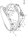
- FIG. 3 shows a supply unit 10 according to the invention for underfloor applications with a snap-in ladder frame 11.
- This latching ladder frame 11 has a closed base body with the frame sides 12, 13, 14, 15.
- the slots of the rows of slots 16 are used for releasably securing device cups, which are not shown in the drawing for the sake of clarity.
- These device cups can be used in the desired height in the supply unit 10 and locked in slots of the row of slots 16 on two opposite sides 12, 14 of the latching conductor frame 11.
- the device cup end has corresponding locking nipple.
- This additional frame 20 consists of two U-shaped frame members 21, 21 '. On the base side 22, 22 'of the U-shaped frame parts 21, 21' slot rows 26, 26 'are provided. These are arranged so that always a row of slots 26 is aligned on the base side 22 with a row of slots 26 'of the base side 22' opposite one another. Furthermore, each slot row 26, 26 'in an assembled supply unit 10 is an extension of the rows of slots 16 of the snap-in ladder frame 11, see Figure 3 ,
- connection of the closed additional frame 20, as in Fig. 1 is shown, with the latching conductor frame 11 is achieved via a clamping connection.
- a clamping connection For this purpose, on the additional frame 20 from the top 29 of the additional frame 20 upwardly projecting clamping arms 25, 25 'are provided.
- two clamping arms 25 and 25 'on the base sides 22, 22' are integrally formed. These are arranged between the rows of slots 26 and 26 'and affect in this way the mounting option for the device cup not.
- one each Clamping arm 25, 25 'in the region of the connection point between the two frame parts 21, 21' is provided.
- 20 more clamping arms 25, 25 ' may be integrally formed on these two sides of the additional frame.
- the additional frame 20 may be a one-piece frame or, as in particular Fig. 2 to see, from two U-shaped frame parts 21, 21 ', which are connected to one another via a latching connection.
- a recess 36 is provided on the leg 23 of the frame part 21. This recess 36 starts from the end face 33 of the leg 23 and extends in the direction of the leg 23.
- the leg 23 in this area has a greater wall thickness, wherein the wall thickness reinforcement is provided on the outside of the leg 23, so that the recess 36 , which originates from the end face 33 of the leg 23, leads through the wall thickness reinforcement and ends adjacent to the wall of the leg 23.
- a latching arm 35 'of the leg 24' of the frame part 21 'to Connection formation are inserted until the end of the locking arm 35 'provided locking lug 38' has passed the recess 36 and hooked at the exit of the recess 36, as shown in Fig. 1 you can see.
- the connection between the latching arm 35, formed on the leg 24 of the frame part 21 with the latching recess 36 ', provided on the leg 23' of the frame part 21 ' is achieved simultaneously. Both latching arms 35, 35 'are on the outside of the legs 24, 24' integrally formed.
- the recess 36, 36 ' can also be designed as a blind hole, wherein for latching the locking lugs 38, 38' corresponding locking grooves are provided within such a recess.
- both frame parts 21, 21 ' are identical. It is of course also possible to equip frame parts only with locking arms and to provide corresponding frame parts only with recesses. Also, other connection means between the frame parts are possible. However, a locking connection is a simple connection option, which can be achieved with little expenditure of time. Furthermore, the latching elements can easily be molded during the production of the frame parts 21, 21 'in the plastic injection molding process.
- the latching connections between the latching arm 35 and the latching recess 36 'and the latching arm 35' and the latching recess 36 on the outer sides 31 of the additional frame 20 are closed, so that the compounds, the inner surfaces of the additional frame and thus the installation space of the supply unit 10 is not influence.
- the additional frame 20 has a smooth inner side 30, which ensures sufficient space for the insertion of the device cup.
- supply unit 10 with snap-in ladder frame 11 and additional frame 20 can be increased by another additional frame 20 so that a further locking conductor extension is achieved.
- another, similar shaped additional frame 20 is attached from below to the already mounted additional frame 20 and a clamping connection between the clamping arms 25 of the lower auxiliary frame with recesses 27, 27 'achieved on the upper auxiliary frame 20.
- the recesses are in the Fig. 1 and 2 shown. They are arranged on the outer side 31 of the additional frame 20 below the clamping arms 25.
Landscapes
- Engineering & Computer Science (AREA)
- Architecture (AREA)
- Civil Engineering (AREA)
- Structural Engineering (AREA)
- Connector Housings Or Holding Contact Members (AREA)
- Auxiliary Devices For And Details Of Packaging Control (AREA)
Claims (13)
- Unité d'approvisionnement pour applications sous plancher, avec un cadre à échelles encliquetables (11) doté d'au moins une rangée de fentes (16) sur chacun de deux côtés opposés (12, 14) du cadre à échelles encliquetables (11), sachant que des boîtes d'appareillage peuvent être installées à différentes profondeurs d'installation dans le cadre à échelles encliquetables (11), caractérisée en ce qu'il est prévu comme rallonge de cadre à échelles encliquetables au moins un cadre auxiliaire (20) qui est équipé de la même manière que le cadre à échelles encliquetables (11) d'au moins une rangée de fentes (26) sur chacun de deux côtés opposés, sachant que le cadre auxiliaire (20) peut être assemblé de manière amovible au cadre à échelles encliquetables (11) afin d'augmenter la profondeur d'installation pour une boîte d'appareillage.
- Unité d'approvisionnement selon la revendication 1, caractérisée en ce que le cadre auxiliaire (20) constitue un cadre fermé qui peut être assemblé au cadre à échelles encliquetables (11) au moyen d'une liaison par serrage.
- Unité d'approvisionnement selon la revendication 2, caractérisée en ce que la liaison par serrage entre les éléments de serrage prévus sur le cadre à échelles encliquetables (11) et sur le cadre auxiliaire (20) peut être réalisée ou défaite en direction verticale.
- Unité d'approvisionnement selon la revendication 3, caractérisée en ce que des évidements (17) sont prévus sur le cadre à échelles encliquetables (11), dans lesquels s'enclenchent des bras de serrage (25) du cadre auxiliaire (20) qui font saillie vers le haut.
- Unité d'approvisionnement selon l'une des revendications 1 à 4, caractérisée en ce que le cadre auxiliaire (20) est réalisé d'un seul tenant.
- Unité d'approvisionnement selon l'une des revendications 1 à 4, caractérisée en ce que le cadre auxiliaire (20) est composé de deux parties de cadre (21, 21') en forme de U, de préférence de deux parties de cadre (21, 21') de configuration identique.
- Unité d'approvisionnement selon la revendication 6, caractérisée en ce les rangées de fentes (26) sont prévues sur le côté de base (22, 22') des parties de cadre (21, 21') en forme de U, et des éléments d'enclenchement sont prévus aux extrémités des branches (23, 24 ; 23', 24') des parties de cadre (21, 21') en forme de U.
- Unité d'approvisionnement selon la revendication 7, caractérisée en ce qu'un bras d'enclenchement (35) est prévu à l'extrémité de la branche (24) de la première partie de cadre (21) en forme de U, bras qui dépasse de la face d'extrémité (32) de la branche (24), et un évidement d'enclenchement (36) partant de la face d'extrémité (33) est prévu sur l'autre branche (23), sachant que le bras d'enclenchement (35) et l'évidement d'enclenchement (36) coopèrent respectivement avec un évidement d'enclenchement (36') et un bras d'enclenchement (35') sur les branches (23', 24') de la deuxième partie de cadre (21') en forme de U.
- Unité d'approvisionnement selon l'une des revendications 1 à 8, caractérisée en ce que le cadre auxiliaire (20) peut être assemblé à d'autres cadres auxiliaires au moyen d'une liaison par serrage et possède à cet effet un évidement respectif (27), ouvert vers le bas, en dessous de chacun des bras de serrage (25) faisant saillie vers le haut.
- Unité d'approvisionnement selon l'une des revendications 2 à 9, caractérisée en ce que les éléments d'enclenchement (35, 35' ; 36, 36') et les éléments de serrage (25, 27) sont prévus sur la face extérieure (31) du cadre auxiliaire (20).
- Unité d'approvisionnement selon l'une des revendications 1 à 10, caractérisée en ce que trois paires de rangées de fentes opposées (16, 26) sont respectivement prévues sur le cadre à échelles encliquetables (11) et sur le cadre auxiliaire (20).
- Unité d'approvisionnement selon la revendication 7, caractérisée en ce que les éléments de serrage (25, 27) sur le côté de base (22) sont respectivement disposés entre deux rangées de fentes voisines (26).
- Unité d'approvisionnement selon l'une des revendications 1 à 12, caractérisée en ce que le cadre auxiliaire (20) est constitué de matière plastique et est fabriqué par moulage par injection.
Applications Claiming Priority (2)
| Application Number | Priority Date | Filing Date | Title |
|---|---|---|---|
| DE200820004144 DE202008004144U1 (de) | 2008-03-26 | 2008-03-26 | Versorgungseinheit für Unterfluranwendung |
| DE200810015770 DE102008015770B4 (de) | 2008-03-26 | 2008-03-26 | Versorgungseinheit für Unterfluranwendung |
Publications (3)
| Publication Number | Publication Date |
|---|---|
| EP2106005A2 EP2106005A2 (fr) | 2009-09-30 |
| EP2106005A3 EP2106005A3 (fr) | 2016-11-30 |
| EP2106005B1 true EP2106005B1 (fr) | 2018-05-09 |
Family
ID=40821782
Family Applications (1)
| Application Number | Title | Priority Date | Filing Date |
|---|---|---|---|
| EP09003998.3A Not-in-force EP2106005B1 (fr) | 2008-03-26 | 2009-03-20 | Unité d'alimentation pour application sous plancher |
Country Status (1)
| Country | Link |
|---|---|
| EP (1) | EP2106005B1 (fr) |
Cited By (1)
| Publication number | Priority date | Publication date | Assignee | Title |
|---|---|---|---|---|
| US11557888B2 (en) | 2019-02-14 | 2023-01-17 | Erico International Corporation | Adjustable depth electrical wall mount ring |
Family Cites Families (8)
| Publication number | Priority date | Publication date | Assignee | Title |
|---|---|---|---|---|
| US2930504A (en) * | 1957-07-22 | 1960-03-29 | Nat Supply Co | Electrical junction box |
| DE7048119U (de) * | 1970-12-30 | 1971-04-15 | Carl Otto | Unterputz Abzweigkasten |
| DE3403053A1 (de) * | 1984-01-30 | 1985-08-01 | Plast-Metall Wilfried Ott, 3012 Langenhagen | Schalterdose |
| US4634015A (en) * | 1985-07-15 | 1987-01-06 | Taylor Jerald M | Adjustable electric outlet box |
| DE60234498D1 (de) * | 2002-04-19 | 2010-01-07 | C & C Marshall Ltd | Zubehörmontage |
| US7053301B2 (en) * | 2004-08-16 | 2006-05-30 | Hubbell Incorporated | Electrical box extension |
| DE102004059815B4 (de) * | 2004-12-07 | 2011-03-24 | Obo Bettermann Gmbh & Co. Kg | Montageträger für Unterflurdose |
| DE202006001321U1 (de) * | 2006-01-23 | 2006-04-06 | Obo Bettermann Gmbh & Co.Kg | Bodeneinbaudose für elektrische Installationsgeräte |
-
2009
- 2009-03-20 EP EP09003998.3A patent/EP2106005B1/fr not_active Not-in-force
Non-Patent Citations (1)
| Title |
|---|
| None * |
Cited By (1)
| Publication number | Priority date | Publication date | Assignee | Title |
|---|---|---|---|---|
| US11557888B2 (en) | 2019-02-14 | 2023-01-17 | Erico International Corporation | Adjustable depth electrical wall mount ring |
Also Published As
| Publication number | Publication date |
|---|---|
| EP2106005A3 (fr) | 2016-11-30 |
| EP2106005A2 (fr) | 2009-09-30 |
Similar Documents
| Publication | Publication Date | Title |
|---|---|---|
| DE102006016882B4 (de) | Steckverbinder | |
| DE10313358B3 (de) | Patchpanel zur Montage an einer Wand oder in einem Baugruppenträger | |
| DE29623551U1 (de) | Schaltschrank | |
| DE102015112563A1 (de) | Verbindungsanordnung zum Verbinden eines Pfostens an einem Rahmenprofil eines Fensters oder einer Türe aus Kunststoff | |
| DE8530054U1 (de) | Elektrischer Stecker | |
| DE102009029434B4 (de) | Adapter zur Aufnahme elektrischer Installationsgeräte und zur Befestigung auf einem Stromschienensystem | |
| DE102007059204A1 (de) | Schaltschrank oder Rack | |
| DE102016123889A1 (de) | Verbindungsanordnung zum Verbinden eines Pfostens mit einem Rahmenprofil eines Fensters oder einer Türe aus Kunststoff | |
| EP2106005B1 (fr) | Unité d'alimentation pour application sous plancher | |
| DE202010010424U1 (de) | Wanddurchführungsklemme für elektrische Leiter | |
| EP1193822B1 (fr) | Support de barres bus | |
| DE102008015770B4 (de) | Versorgungseinheit für Unterfluranwendung | |
| DE4433617A1 (de) | Elektrisches Steckverbindungsteil | |
| EP0749180B1 (fr) | Boítier de connecteur à fiche | |
| DE4328447C2 (de) | Unterflurgerätedose | |
| DE202008004144U1 (de) | Versorgungseinheit für Unterfluranwendung | |
| EP1352120B1 (fr) | Adaptateur destine a la fixation de regulateurs de niveau d'eau | |
| DE3506119A1 (de) | Kabelverzweigerschrank | |
| DE10135662A1 (de) | Gerätebecherrahmen für Unterfluranwendungen | |
| DE102005042746B4 (de) | Sicherungslasttrennschalter | |
| DE10001203C1 (de) | Gehäuse mit verrastbaren Gehäuseteilen | |
| DE9005067U1 (de) | Einschub mit Montageplatte | |
| BE1020602A3 (de) | Hohlwanddose aus kunststoff. | |
| DE7304831U (de) | Elektrische Verbinderanordnung | |
| DE9205545U1 (de) | Steckverbinder |
Legal Events
| Date | Code | Title | Description |
|---|---|---|---|
| PUAI | Public reference made under article 153(3) epc to a published international application that has entered the european phase |
Free format text: ORIGINAL CODE: 0009012 |
|
| AK | Designated contracting states |
Kind code of ref document: A2 Designated state(s): AT BE BG CH CY CZ DE DK EE ES FI FR GB GR HR HU IE IS IT LI LT LU LV MC MK MT NL NO PL PT RO SE SI SK TR |
|
| AX | Request for extension of the european patent |
Extension state: AL BA RS |
|
| PUAL | Search report despatched |
Free format text: ORIGINAL CODE: 0009013 |
|
| AK | Designated contracting states |
Kind code of ref document: A3 Designated state(s): AT BE BG CH CY CZ DE DK EE ES FI FR GB GR HR HU IE IS IT LI LT LU LV MC MK MT NL NO PL PT RO SE SI SK TR |
|
| AX | Request for extension of the european patent |
Extension state: AL BA RS |
|
| RIC1 | Information provided on ipc code assigned before grant |
Ipc: H02G 3/18 20060101AFI20161025BHEP |
|
| STAA | Information on the status of an ep patent application or granted ep patent |
Free format text: STATUS: REQUEST FOR EXAMINATION WAS MADE |
|
| 17P | Request for examination filed |
Effective date: 20170522 |
|
| RBV | Designated contracting states (corrected) |
Designated state(s): AT BE BG CH CY CZ DE DK EE ES FI FR GB GR HR HU IE IS IT LI LT LU LV MC MK MT NL NO PL PT RO SE SI SK TR |
|
| AKX | Designation fees paid |
Designated state(s): AT BE BG CH CY CZ DE DK EE ES FI FR GB GR HR HU IE IS IT LI LT LU LV MC MK MT NL NO PL PT RO SE SI SK TR |
|
| AXX | Extension fees paid |
Extension state: BA Extension state: RS Extension state: AL |
|
| GRAP | Despatch of communication of intention to grant a patent |
Free format text: ORIGINAL CODE: EPIDOSNIGR1 |
|
| STAA | Information on the status of an ep patent application or granted ep patent |
Free format text: STATUS: GRANT OF PATENT IS INTENDED |
|
| INTG | Intention to grant announced |
Effective date: 20171113 |
|
| RAP1 | Party data changed (applicant data changed or rights of an application transferred) |
Owner name: TEHALIT GMBH |
|
| GRAS | Grant fee paid |
Free format text: ORIGINAL CODE: EPIDOSNIGR3 |
|
| GRAA | (expected) grant |
Free format text: ORIGINAL CODE: 0009210 |
|
| STAA | Information on the status of an ep patent application or granted ep patent |
Free format text: STATUS: THE PATENT HAS BEEN GRANTED |
|
| AK | Designated contracting states |
Kind code of ref document: B1 Designated state(s): AT BE BG CH CY CZ DE DK EE ES FI FR GB GR HR HU IE IS IT LI LT LU LV MC MK MT NL NO PL PT RO SE SI SK TR |
|
| REG | Reference to a national code |
Ref country code: GB Ref legal event code: FG4D Free format text: NOT ENGLISH |
|
| REG | Reference to a national code |
Ref country code: CH Ref legal event code: EP Ref country code: AT Ref legal event code: REF Ref document number: 998383 Country of ref document: AT Kind code of ref document: T Effective date: 20180515 |
|
| REG | Reference to a national code |
Ref country code: IE Ref legal event code: FG4D Free format text: LANGUAGE OF EP DOCUMENT: GERMAN |
|
| REG | Reference to a national code |
Ref country code: DE Ref legal event code: R096 Ref document number: 502009014942 Country of ref document: DE |
|
| REG | Reference to a national code |
Ref country code: NL Ref legal event code: FP |
|
| REG | Reference to a national code |
Ref country code: LT Ref legal event code: MG4D |
|
| PG25 | Lapsed in a contracting state [announced via postgrant information from national office to epo] |
Ref country code: BG Free format text: LAPSE BECAUSE OF FAILURE TO SUBMIT A TRANSLATION OF THE DESCRIPTION OR TO PAY THE FEE WITHIN THE PRESCRIBED TIME-LIMIT Effective date: 20180809 Ref country code: LT Free format text: LAPSE BECAUSE OF FAILURE TO SUBMIT A TRANSLATION OF THE DESCRIPTION OR TO PAY THE FEE WITHIN THE PRESCRIBED TIME-LIMIT Effective date: 20180509 Ref country code: FI Free format text: LAPSE BECAUSE OF FAILURE TO SUBMIT A TRANSLATION OF THE DESCRIPTION OR TO PAY THE FEE WITHIN THE PRESCRIBED TIME-LIMIT Effective date: 20180509 Ref country code: ES Free format text: LAPSE BECAUSE OF FAILURE TO SUBMIT A TRANSLATION OF THE DESCRIPTION OR TO PAY THE FEE WITHIN THE PRESCRIBED TIME-LIMIT Effective date: 20180509 Ref country code: NO Free format text: LAPSE BECAUSE OF FAILURE TO SUBMIT A TRANSLATION OF THE DESCRIPTION OR TO PAY THE FEE WITHIN THE PRESCRIBED TIME-LIMIT Effective date: 20180809 Ref country code: SE Free format text: LAPSE BECAUSE OF FAILURE TO SUBMIT A TRANSLATION OF THE DESCRIPTION OR TO PAY THE FEE WITHIN THE PRESCRIBED TIME-LIMIT Effective date: 20180509 |
|
| PG25 | Lapsed in a contracting state [announced via postgrant information from national office to epo] |
Ref country code: LV Free format text: LAPSE BECAUSE OF FAILURE TO SUBMIT A TRANSLATION OF THE DESCRIPTION OR TO PAY THE FEE WITHIN THE PRESCRIBED TIME-LIMIT Effective date: 20180509 Ref country code: HR Free format text: LAPSE BECAUSE OF FAILURE TO SUBMIT A TRANSLATION OF THE DESCRIPTION OR TO PAY THE FEE WITHIN THE PRESCRIBED TIME-LIMIT Effective date: 20180509 Ref country code: GR Free format text: LAPSE BECAUSE OF FAILURE TO SUBMIT A TRANSLATION OF THE DESCRIPTION OR TO PAY THE FEE WITHIN THE PRESCRIBED TIME-LIMIT Effective date: 20180810 |
|
| PG25 | Lapsed in a contracting state [announced via postgrant information from national office to epo] |
Ref country code: SK Free format text: LAPSE BECAUSE OF FAILURE TO SUBMIT A TRANSLATION OF THE DESCRIPTION OR TO PAY THE FEE WITHIN THE PRESCRIBED TIME-LIMIT Effective date: 20180509 Ref country code: RO Free format text: LAPSE BECAUSE OF FAILURE TO SUBMIT A TRANSLATION OF THE DESCRIPTION OR TO PAY THE FEE WITHIN THE PRESCRIBED TIME-LIMIT Effective date: 20180509 Ref country code: CZ Free format text: LAPSE BECAUSE OF FAILURE TO SUBMIT A TRANSLATION OF THE DESCRIPTION OR TO PAY THE FEE WITHIN THE PRESCRIBED TIME-LIMIT Effective date: 20180509 Ref country code: PL Free format text: LAPSE BECAUSE OF FAILURE TO SUBMIT A TRANSLATION OF THE DESCRIPTION OR TO PAY THE FEE WITHIN THE PRESCRIBED TIME-LIMIT Effective date: 20180509 Ref country code: EE Free format text: LAPSE BECAUSE OF FAILURE TO SUBMIT A TRANSLATION OF THE DESCRIPTION OR TO PAY THE FEE WITHIN THE PRESCRIBED TIME-LIMIT Effective date: 20180509 Ref country code: DK Free format text: LAPSE BECAUSE OF FAILURE TO SUBMIT A TRANSLATION OF THE DESCRIPTION OR TO PAY THE FEE WITHIN THE PRESCRIBED TIME-LIMIT Effective date: 20180509 |
|
| REG | Reference to a national code |
Ref country code: DE Ref legal event code: R097 Ref document number: 502009014942 Country of ref document: DE |
|
| PG25 | Lapsed in a contracting state [announced via postgrant information from national office to epo] |
Ref country code: IT Free format text: LAPSE BECAUSE OF FAILURE TO SUBMIT A TRANSLATION OF THE DESCRIPTION OR TO PAY THE FEE WITHIN THE PRESCRIBED TIME-LIMIT Effective date: 20180509 |
|
| PLBE | No opposition filed within time limit |
Free format text: ORIGINAL CODE: 0009261 |
|
| STAA | Information on the status of an ep patent application or granted ep patent |
Free format text: STATUS: NO OPPOSITION FILED WITHIN TIME LIMIT |
|
| 26N | No opposition filed |
Effective date: 20190212 |
|
| PG25 | Lapsed in a contracting state [announced via postgrant information from national office to epo] |
Ref country code: SI Free format text: LAPSE BECAUSE OF FAILURE TO SUBMIT A TRANSLATION OF THE DESCRIPTION OR TO PAY THE FEE WITHIN THE PRESCRIBED TIME-LIMIT Effective date: 20180509 |
|
| PG25 | Lapsed in a contracting state [announced via postgrant information from national office to epo] |
Ref country code: MC Free format text: LAPSE BECAUSE OF FAILURE TO SUBMIT A TRANSLATION OF THE DESCRIPTION OR TO PAY THE FEE WITHIN THE PRESCRIBED TIME-LIMIT Effective date: 20180509 |
|
| REG | Reference to a national code |
Ref country code: CH Ref legal event code: PL |
|
| GBPC | Gb: european patent ceased through non-payment of renewal fee |
Effective date: 20190320 |
|
| PG25 | Lapsed in a contracting state [announced via postgrant information from national office to epo] |
Ref country code: LU Free format text: LAPSE BECAUSE OF NON-PAYMENT OF DUE FEES Effective date: 20190320 |
|
| REG | Reference to a national code |
Ref country code: BE Ref legal event code: MM Effective date: 20190331 |
|
| PG25 | Lapsed in a contracting state [announced via postgrant information from national office to epo] |
Ref country code: CH Free format text: LAPSE BECAUSE OF NON-PAYMENT OF DUE FEES Effective date: 20190331 Ref country code: LI Free format text: LAPSE BECAUSE OF NON-PAYMENT OF DUE FEES Effective date: 20190331 Ref country code: GB Free format text: LAPSE BECAUSE OF NON-PAYMENT OF DUE FEES Effective date: 20190320 Ref country code: IE Free format text: LAPSE BECAUSE OF NON-PAYMENT OF DUE FEES Effective date: 20190320 |
|
| PG25 | Lapsed in a contracting state [announced via postgrant information from national office to epo] |
Ref country code: BE Free format text: LAPSE BECAUSE OF NON-PAYMENT OF DUE FEES Effective date: 20190331 |
|
| PG25 | Lapsed in a contracting state [announced via postgrant information from national office to epo] |
Ref country code: TR Free format text: LAPSE BECAUSE OF FAILURE TO SUBMIT A TRANSLATION OF THE DESCRIPTION OR TO PAY THE FEE WITHIN THE PRESCRIBED TIME-LIMIT Effective date: 20180509 |
|
| PG25 | Lapsed in a contracting state [announced via postgrant information from national office to epo] |
Ref country code: PT Free format text: LAPSE BECAUSE OF FAILURE TO SUBMIT A TRANSLATION OF THE DESCRIPTION OR TO PAY THE FEE WITHIN THE PRESCRIBED TIME-LIMIT Effective date: 20180910 Ref country code: MT Free format text: LAPSE BECAUSE OF FAILURE TO SUBMIT A TRANSLATION OF THE DESCRIPTION OR TO PAY THE FEE WITHIN THE PRESCRIBED TIME-LIMIT Effective date: 20180509 |
|
| REG | Reference to a national code |
Ref country code: AT Ref legal event code: MM01 Ref document number: 998383 Country of ref document: AT Kind code of ref document: T Effective date: 20190320 |
|
| PG25 | Lapsed in a contracting state [announced via postgrant information from national office to epo] |
Ref country code: AT Free format text: LAPSE BECAUSE OF NON-PAYMENT OF DUE FEES Effective date: 20190320 |
|
| PG25 | Lapsed in a contracting state [announced via postgrant information from national office to epo] |
Ref country code: CY Free format text: LAPSE BECAUSE OF FAILURE TO SUBMIT A TRANSLATION OF THE DESCRIPTION OR TO PAY THE FEE WITHIN THE PRESCRIBED TIME-LIMIT Effective date: 20180509 |
|
| PG25 | Lapsed in a contracting state [announced via postgrant information from national office to epo] |
Ref country code: IS Free format text: LAPSE BECAUSE OF FAILURE TO SUBMIT A TRANSLATION OF THE DESCRIPTION OR TO PAY THE FEE WITHIN THE PRESCRIBED TIME-LIMIT Effective date: 20180909 |
|
| PG25 | Lapsed in a contracting state [announced via postgrant information from national office to epo] |
Ref country code: HU Free format text: LAPSE BECAUSE OF FAILURE TO SUBMIT A TRANSLATION OF THE DESCRIPTION OR TO PAY THE FEE WITHIN THE PRESCRIBED TIME-LIMIT; INVALID AB INITIO Effective date: 20090320 |
|
| PG25 | Lapsed in a contracting state [announced via postgrant information from national office to epo] |
Ref country code: MK Free format text: LAPSE BECAUSE OF FAILURE TO SUBMIT A TRANSLATION OF THE DESCRIPTION OR TO PAY THE FEE WITHIN THE PRESCRIBED TIME-LIMIT Effective date: 20180509 |
|
| PGFP | Annual fee paid to national office [announced via postgrant information from national office to epo] |
Ref country code: NL Payment date: 20230326 Year of fee payment: 15 |
|
| P01 | Opt-out of the competence of the unified patent court (upc) registered |
Effective date: 20230606 |
|
| PGFP | Annual fee paid to national office [announced via postgrant information from national office to epo] |
Ref country code: DE Payment date: 20240327 Year of fee payment: 16 |
|
| PGFP | Annual fee paid to national office [announced via postgrant information from national office to epo] |
Ref country code: FR Payment date: 20240325 Year of fee payment: 16 |
|
| REG | Reference to a national code |
Ref country code: NL Ref legal event code: MM Effective date: 20240401 |
|
| PG25 | Lapsed in a contracting state [announced via postgrant information from national office to epo] |
Ref country code: NL Free format text: LAPSE BECAUSE OF NON-PAYMENT OF DUE FEES Effective date: 20240401 |
|
| PG25 | Lapsed in a contracting state [announced via postgrant information from national office to epo] |
Ref country code: NL Free format text: LAPSE BECAUSE OF NON-PAYMENT OF DUE FEES Effective date: 20240401 |
|
| REG | Reference to a national code |
Ref country code: DE Ref legal event code: R119 Ref document number: 502009014942 Country of ref document: DE |
|
| PG25 | Lapsed in a contracting state [announced via postgrant information from national office to epo] |
Ref country code: DE Free format text: LAPSE BECAUSE OF NON-PAYMENT OF DUE FEES Effective date: 20251001 |
|
| PG25 | Lapsed in a contracting state [announced via postgrant information from national office to epo] |
Ref country code: FR Free format text: LAPSE BECAUSE OF NON-PAYMENT OF DUE FEES Effective date: 20250331 |