EP2106200A2 - Dispositif d'éclairage par lampe à décharge et accessoire d'illumination - Google Patents
Dispositif d'éclairage par lampe à décharge et accessoire d'illumination Download PDFInfo
- Publication number
- EP2106200A2 EP2106200A2 EP09156082A EP09156082A EP2106200A2 EP 2106200 A2 EP2106200 A2 EP 2106200A2 EP 09156082 A EP09156082 A EP 09156082A EP 09156082 A EP09156082 A EP 09156082A EP 2106200 A2 EP2106200 A2 EP 2106200A2
- Authority
- EP
- European Patent Office
- Prior art keywords
- discharge lamp
- lamp
- preheating
- filament
- lighting device
- Prior art date
- Legal status (The legal status is an assumption and is not a legal conclusion. Google has not performed a legal analysis and makes no representation as to the accuracy of the status listed.)
- Withdrawn
Links
- 238000005286 illumination Methods 0.000 title claims description 9
- 238000001514 detection method Methods 0.000 claims abstract description 10
- 239000011521 glass Substances 0.000 description 13
- 238000000034 method Methods 0.000 description 12
- 239000003990 capacitor Substances 0.000 description 7
- 238000004804 winding Methods 0.000 description 6
- 238000012937 correction Methods 0.000 description 5
- 238000010586 diagram Methods 0.000 description 5
- 239000011248 coating agent Substances 0.000 description 4
- 238000000576 coating method Methods 0.000 description 4
- 230000007423 decrease Effects 0.000 description 3
- 230000006866 deterioration Effects 0.000 description 3
- 230000006870 function Effects 0.000 description 3
- 230000001747 exhibiting effect Effects 0.000 description 2
- WABPQHHGFIMREM-UHFFFAOYSA-N lead(0) Chemical compound [Pb] WABPQHHGFIMREM-UHFFFAOYSA-N 0.000 description 2
- 230000010355 oscillation Effects 0.000 description 2
- OAICVXFJPJFONN-UHFFFAOYSA-N Phosphorus Chemical compound [P] OAICVXFJPJFONN-UHFFFAOYSA-N 0.000 description 1
- 230000015556 catabolic process Effects 0.000 description 1
- 239000004020 conductor Substances 0.000 description 1
- 230000000694 effects Effects 0.000 description 1
- 238000009413 insulation Methods 0.000 description 1
- 238000002844 melting Methods 0.000 description 1
- 230000008018 melting Effects 0.000 description 1
- 239000000126 substance Substances 0.000 description 1
Images


Classifications
-
- H—ELECTRICITY
- H05—ELECTRIC TECHNIQUES NOT OTHERWISE PROVIDED FOR
- H05B—ELECTRIC HEATING; ELECTRIC LIGHT SOURCES NOT OTHERWISE PROVIDED FOR; CIRCUIT ARRANGEMENTS FOR ELECTRIC LIGHT SOURCES, IN GENERAL
- H05B41/00—Circuit arrangements or apparatus for igniting or operating discharge lamps
- H05B41/14—Circuit arrangements
- H05B41/26—Circuit arrangements in which the lamp is fed by power derived from DC by means of a converter, e.g. by high-voltage DC
- H05B41/28—Circuit arrangements in which the lamp is fed by power derived from DC by means of a converter, e.g. by high-voltage DC using static converters
- H05B41/295—Circuit arrangements in which the lamp is fed by power derived from DC by means of a converter, e.g. by high-voltage DC using static converters with semiconductor devices and specially adapted for lamps with preheating electrodes, e.g. for fluorescent lamps
-
- H—ELECTRICITY
- H05—ELECTRIC TECHNIQUES NOT OTHERWISE PROVIDED FOR
- H05B—ELECTRIC HEATING; ELECTRIC LIGHT SOURCES NOT OTHERWISE PROVIDED FOR; CIRCUIT ARRANGEMENTS FOR ELECTRIC LIGHT SOURCES, IN GENERAL
- H05B41/00—Circuit arrangements or apparatus for igniting or operating discharge lamps
- H05B41/14—Circuit arrangements
- H05B41/36—Controlling
Definitions
- the present invention relates to a discharge lamp lighting device for lighting a discharge lamp having a thermal cathode, and a illumination fixture using thereof.
- Discharge lamps such as fluorescent lamps are variously rated in general. Discharge lamps are different not only in a structural size, a shape and a filament structure or the like, but also in electrical characteristics such as a lamp voltage and a lamp current in normal lighting, a starting voltage at the starting time, and preheating current characteristics at the preheating time. As a result, a discharge lamp lighting device has been exclusively used for a fluorescent lamp according to a product name thereof in substantially one to one corresponding relationship.
- a technique progress in the lighting device in recent years has made it possible to use a lighting device commonly for fluorescent lamps of plural ratings with a similar structure and similar electrical characteristics, and mainstream discharge lamp lighting devices in, for example, a class with a straight tube length of 4 feet include a lighting device for FHF32 which is also capable of lighting other lamps such as FLR40S/36 and FL40SS/37.
- fluorescent lamps or so-called T5 lamps with a tube diameter of 16mm in the same shape and size with those in a class with a tube length of 4 feet are divided into two types of lamps including 54W (HO: lamp current 400mA, lamp voltage 135V) and 28W (HE: lamp current 170mA, lamp voltage 165V), and their difference is approximately double in the rating. Therefore, it is impossible to commonly use a lighting device in the same manner with treating the above FHF32, FLR40S/36 and FLR40S/36.
- a type determination means adapted to determine the type of a lamp and a control means adapted to variably control an oscillation frequency of a lighting circuit and an output voltage of a DC power source circuit are provided so as to obtain the rating of individual adaptable lamps when each of the lamps is lit. More specifically, the type of a lamp is determined by a resistance value of a filament in each fluorescent lamp, a lamp voltage and a lamp current in lighting each lamp.
- Patent document 1 proposes a configuration in which a single lighting device is commonly used for mounting fluorescent lamps with different ratings in the same shape by determining the type of lamps using a filament resistance value, a lamp voltage and a lamp current or the like and changing over a switching frequency of an inverter.
- this new lamp which maintains electrical compatibility with the conventional lamp has a lamp voltage substantially equivalent to that of the conventional lamp, so that it is impossible to determine the type of the lamp by a lamp voltage at the time of lighting.
- a slight difference in the filament resistance also makes it difficult to determine the type of the lamps by a filament resistance value obtained before lighting the lamps in a cold state. Accordingly, it is extremely difficult to determine the difference between the conventional lamp and the new lamp even if the technique as disclosed in Patent Document 1 is used.
- the present invention has achieved by taking the above problems into consideration and an object thereof is to light a plurality of lamps with compatible electrical characteristics and considerably different rated power by using a common lighting device.
- a first aspect of the present invention is to provide a discharge lamp lighting device capable of lighting plural types of discharge lamps with different recommended conditions of precedent preheating for filament and determining the type of a discharge lamp by detecting a voltage at both ends of a filament within a period of precedent preheating time, wherein a higher current value included in the recommended conditions is used for a preheating current in the detection, and an output is set to be applicable to rated power of a determined discharge lamp, in order to solve the above problems as shown in Figs. 1 to 3 .
- a second aspect of the present invention is to provide a discharge lamp lighting device capable of lighting plural types of discharge lamps with different recommended conditions of precedent preheating for filament and determining the type of a discharge lamp by detecting a voltage at both ends of a filament within a period of precedent preheating time, wherein a preheating current used in the detection has a current value to cause a discharge between electrodes in the vicinity of the filament within the period of the precedent preheating time if a discharge lamp with low criteria of the recommended conditions is mounted, and an output is set to be applicable to rated power of a determined discharge lamp, in order to solve the above problems as shown in Figs. 3 to 5 .
- a third aspect of the present invention is based on the discharge lamp lighting device according to any one of the first and second aspects of the present invention, wherein the type of a mounted discharge lamp is determined only at the initial precedent preheating time, an output thereafter is set to be applicable to the initially determined discharge lamp, and determination information of the discharge lamp is reset when the discharge lamp is removed.
- a fourth aspect of the present invention is based on the discharge lamp lighting device according to any one of the first to third aspects of the present invention, wherein the plurality of the discharge lamps has a difference of 1.5 times or more in the amount of emitter coated on a filament.
- a fifth aspect of the present invention is to provide a illumination fixture including the discharge lamp lighting device according to any one of the first to fourth aspects of the present invention, a fixture main body 31 for mounting the discharge lamp lighting device, and a socket 32 arranged in the fixture main body 31 so as to attachably/detachably mount a discharge 21 and electrically connect the discharge lamp lighting device and the discharge lamp 21.
- the present invention makes it possible to light a plurality of lamps with compatible electrical characteristics and considerably different rated power by using a common lighting device.
- the type of a plurality of lamps with different recommended conditions of precedent preheating for filament can be easily determined by causing a higher current included in the recommended conditions to flow in a filament to detect a voltage at both ends of the filament. It is also made possible to light a plurality of lamps with considerably different rated power in a common lighting device by setting the lighting device to have an output applicable to rated power of a connected lamp. It is further possible to realize the determination within a short period of time because a lamp can be determined within a period of precedent preheating time.
- the type of a plurality of lamps with different recommended conditions of precedent preheating for filament can be easily determined by applying a voltage, which causes a discharge between electrodes of a filament, to a filament if a discharge lamp with lower criteria of the recommended conditions is mounted.
- a mounted discharge lamp is determined only at the initial precedent preheating time and an output thereafter in a lighting device is set to be applicable to the initially determined lamp, whereby preventing deterioration of the lamp due to repetition of the determination process. Determination information on a lamp is also reset when the lamp is removed, which makes it possible to realize precedent preheating under recommended conditions constantly even if the lamp is exchanged while being used.
- a plurality of discharge lamps has a difference of 1.5 times or more in an amount of emitter coated on the filament, a remarkable difference will appear in the voltage at both ends of the filament with respect to a preheating current, whereby realizing the determination with higher accuracy.
- an illumination fixture capable of lighting a plurality of lamps with considerably different rated power by using a common lighting device can be provided with the discharge lamp lighting device having a lamp determination function as stated above.
- a lighting device for a fluorescent lamp generally employs "precedent preheating" to heat a filament prior to apply a starting voltage to a lamp so that the time for the lamp to reach an end of life can be extended as long as possible by suppressing consumption of an emitter (i.e. thermal electron emitting substance) which is coated on the filament.
- the present embodiment exemplifies how to determine a discharge lamp by detecting a voltage at both ends of the filament within this precedent preheating time.
- a heat capacity of a filament is made larger than that of a conventional lamp by optimizing a coil design in order to allow the filament to bear the increased lamp current.
- a filament resistance in a cold state is equivalent to or slightly lower than that of the conventional lamp, and using this difference is extremely difficult to determine the type of lamps.
- a recommended condition for a precedent preheating current which is applied to the filament are fixed according to product names of lamps, and a parameter which considerably affects the recommended condition include a heat capacity of the filament. Even if the same preheating current is made to flow in a coil, a large heat capacity of a filament prevents a sufficient temperature rise in the coil, resulting in an insufficient preheating state. That is, the new lamp has a recommended preheating condition with a higher current than that of the conventional lamp.
- Relationship as shown in Fig. 1 is established between a preheating current If and a voltage Vf at both ends of the filament.
- the voltage at both ends of the filament rises as the preheating current is increased, a new lamp with a larger filament preheating capacity has a more gradual rise in the voltage Vf at both ends of the filament with respect to a rise of the preheating current If. It is because a lamp with a larger heat capacity is allowed to further suppress a rise in the resistivity of the filament.
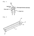
- Filament has a configuration as shown in Fig. 2 .
- 10 represents a coil
- 11 represents a glass bulb
- 12 represents a lead wire
- 13 represents a glass stem.
- the filament has a heat capacity which is determined by factors such as the number, a wire diameter and winding of the coil 10, the length and a wire diameter of the lead wire 12, and a size of the glass stem 13.
- Such characteristics of the filament are used to detect a voltage at both ends of the filament within precedent preheating time during which the preheating current is made to flow, so as to easily determine the type of lamps even if only a slight difference is observed in the resistance of the filament in a cold state.
- a preheating current which is made to flow at that time is set to have a value corresponding to a lamp with a higher preheating current in the recommended conditions in order to further increase a difference in the filament voltage V, which can be therefore a more preferable method.
- If1 shows a recommended preheating current for the conventional lamp
- If2 shows a recommended preheating current for the new lamp.
- a lighting device which determined the lamp is set to have an output applicable to rated power of the lamp to be connected in order to light the lamp, whereby a plurality of lamps with considerably different rated power can be lit by using a common lighting device.
- a lamp is generally being attached to a illumination fixture in a normal usage state until the lamp reaches the end of life, in which the type of the lamp does not need to be determined every time in the precedent preheating and the determination may be executed only at the initial precedent preheating time after mounting the discharge lamp.
- Information on the determination results is written into a storage element such as, for example, a micro computer and a nonvolatile memory, and the information is read in lighting a lamp.
- Stored determination information is reset when a lamp is removed, which enables precedent preheating under recommended conditions constantly except for the initial precedent preheating time even if the type of a lamp is changed while being used.
- Fig. 3 shows a general configuration of the discharge lamp lighting device according to the present embodiment.
- An AC voltage of a commercial AC power source 1 is subjected to full-wave rectification by a full-wave rectifier circuit 2, converted into a smooth DC voltage by a chopper circuit 3, converted into high frequency AC power by an inverter circuit 4, and supplied to a discharge lamp load circuit 5.
- the inverter circuit 4 includes a switching element to be switched by a high frequency, and a resonance circuit which is made of a resonance inductor and a resonance capacitor to be excited by a switched high frequency, having a structure to start/light a discharge lamp by supplying high frequency power generated in the resonance circuit to the discharge lamp load circuit 5.
- An inverter control circuit 8 has a function to control a switching frequency of the switching element so as to shift to a stable lighting mode through a preheating mode for causing a current to flow in the filament in a level without lighting the discharge lamp prior to start the discharge lamp, and a starting mode for applying a high voltage required to start the discharge lamp.
- the discharge lamp load circuit 5 includes a fluorescent lamp and a preheating circuit for the fluorescent lamp.
- the preheating circuit may be configured in a capacitor preheating method and/or a winding preheating method.
- the capacitor preheating method generally provides a configuration in which a preheating capacitor is connected between respective one ends of a pair of filaments of a fluorescent lamp so as to supply high frequency AC power of the inverter circuit 4 to a point between the other respective ends of the pair of the filaments.
- the winging preheating method generally provides a configuration in which a preheating transformer is connected to an output of the inverter circuit 4 via a capacitor so as to supply a preheating current to a pair of filaments of a fluorescent lamp via a preheating capacitor from a pair of secondary windings arranged in the preheating transformer respectively.
- a pair of secondary windings for preheating may be arranged in an inductor (e.g. resonance inductor) of the inverter circuit 4 so as to supply a preheating current to a pair of filaments of a fluorescent lamp via a preheating capacitor from the pair of the secondary windings respectively.
- a configuration may be provided so as to selectively realize a combination of a lamp current applicable to the conventional lamp and a filament current and a combination of a lamp current applicable to the new lamp and a filament current.
- the type of a fluorescent lamp connected to the discharge lamp load circuit 5 is detected by a lamp type detection circuit 6 at the initial precedent preheating time and stored in a storage part of a lamp type correction circuit 7. That is, it is controlled so that the lamp type detection circuit 6 detects the type of the lamp by preheating the new lamp at a recommended preheating current at the initial precedent preheating time, and a recommended preheating current of the conventional lamp or the new lamp is used to preheat the lamp at the next preheating time and thereafter in accordance with the type of a lamp held in the lamp type correction circuit 7.
- corrections are made in the characteristics of the resonance circuit of the inverter 4 in accordance with the type of the lamp held in the lamp type correction circuit 7, an oscillation frequency of the inverter circuit 4 is corrected by the inverter control circuit 8, and an output voltage of the chopper circuit 3 is corrected by a chopper control circuit 9. It is therefore possible to supply an appropriate preheating current and an appropriate lamp current to any one of the conventional lamp and the new lamp to be connected.
- a lamp coated with emitter whose amount is 1.5 times more than that of a normal lamp has been sold by Matsushita Electric Industrial Co., Ltd, and the lamp allows a life of a rated lamp to be multiplied by 1.5 even if a lamp current approximately double the current of a conventional lamp such as FHF32 is made to flow (or even in about double brightness).
- a lamp output can be thus increased by coating emitter 1.5 times more than a normal amount while securing life of the lamp.
- the discharge lamp lighting device makes it possible to supply an appropriate preheating current and an appropriate lamp current even in connecting a conventional lamp such as FHF21 and a new lamp such as a G-Hf fluorescent lamp.
- the first embodiment exemplified a discharge lamp lighting device in which the type of lamps with different recommended conditions of precedent preheating is determined by causing a preheating current If 2, being a higher current in the conditions, to flow in the lamps and detecting the voltage Vf at both ends of the filament, whereas the present embodiment shows an example of causing a much higher preheating current If3 to flow.
- a general configuration in the discharge lamp lighting device may remain the same as that of Fig. 3 .
- a voltage applied to a filament needs to be further increased in order to cause a much higher current to flow.
- the filament is fixed by lead wires 12 arranged on the glass stem 13 as explained in Fig. 2 , wherein a distance of only several to ten and several milliliters is allowed between the lead wires so as to be contained in the glass bulb 11 with a narrow tube diameter, and a shortest distance therebetween is generally in the vicinity of the glass stem 13. If a voltage applied to the filament is increased here, dielectric breakdown occurs between the lead wires and a discharge is observed between the electrodes as shown in Fig. 5 . This phenomenon is used to determine the type of lamps.
- lamps with different recommended conditions of precedent preheating have different characteristics in the voltage Vf at both ends of a filament with respect to the preheating current If, wherein the lamp with lower criteria of the recommended conditions has a larger increase in the filament voltage Vf.
- a voltage applied to the filament is increased here, a large current is made to flow in the coil 10 whose temperature becomes extremely high, and a lamp with lower criteria of the recommended conditions tends to have a higher temperature in the coil 10.
- Heat generated in the coil 10 is conducted to the glass stem 13 via the lead wires 12, so that a high temperature is also observed in the vicinity of the glass stem 13.
- the glass stem 13 behaves like a conductor when discharge is generated between electrodes as shown in Fig. 5 , exhibiting a sharp decrease in the voltage Vf at both ends of a filament as shown in Fig. 4 .
- a lamp with higher criteria of the recommended conditions of precedent preheating is originally based on a design which allows the lamp to bear a high preheating current, whereby a discharge between electrodes is hard to occur and a temperature in the glass stem 13 can be suppressed to low. That is, a high preheating current for causing the conventional lamp to have a decrease in the voltage Vf at both ends of the filament as shown in If3 of Fig. 4 is made to flow (i.e. high voltage is applied to the filament) so as to easily determine the type of lamps.
- Both the first and second embodiments make it possible to determine the type of lamps with different recommended conditions of precedent preheating, and lamps having a difference of 1.5 times or more in the amount of the emitter coated on the coil of the filament exhibit a more remarkable difference in the voltage at both ends of the filament with respect to the preheating current and can be determined with higher accuracy, which is particularly effective.
- Fig. 6 shows an appearance of the illumination fixture to which the discharge lamp lighting device according to the first and second embodiments is mounted.
- Both the first and second embodiments are provided with a fixture main body 31 for integrating the discharge lamp lighting device having a determination function as stated above and fitting the discharge lamp lighting device, and a socket 32 arranged in the fixture main body so as to attachably/detachably mount the discharge lamp 21 and electrically connect the discharge lamp lighting device and the discharge lamp, whereby it is made possible to provide a illumination fixture 30 in which a plurality of lamps with considerably different rated power can be lit by using a common lighting device.
Landscapes
- Circuit Arrangements For Discharge Lamps (AREA)
Applications Claiming Priority (1)
| Application Number | Priority Date | Filing Date | Title |
|---|---|---|---|
| JP2008083661A JP5261000B2 (ja) | 2008-03-27 | 2008-03-27 | 放電灯点灯装置及び照明器具 |
Publications (2)
| Publication Number | Publication Date |
|---|---|
| EP2106200A2 true EP2106200A2 (fr) | 2009-09-30 |
| EP2106200A3 EP2106200A3 (fr) | 2014-12-17 |
Family
ID=40795049
Family Applications (1)
| Application Number | Title | Priority Date | Filing Date |
|---|---|---|---|
| EP09156082.1A Withdrawn EP2106200A3 (fr) | 2008-03-27 | 2009-03-24 | Dispositif d'éclairage par lampe à décharge et accessoire d'illumination |
Country Status (2)
| Country | Link |
|---|---|
| EP (1) | EP2106200A3 (fr) |
| JP (1) | JP5261000B2 (fr) |
Citations (1)
| Publication number | Priority date | Publication date | Assignee | Title |
|---|---|---|---|---|
| JPH11307290A (ja) | 1998-04-23 | 1999-11-05 | Matsushita Electric Works Ltd | 放電灯点灯装置 |
Family Cites Families (10)
| Publication number | Priority date | Publication date | Assignee | Title |
|---|---|---|---|---|
| JPH11307291A (ja) * | 1998-04-23 | 1999-11-05 | Matsushita Electric Works Ltd | 放電灯点灯装置 |
| JPH11307289A (ja) * | 1998-04-23 | 1999-11-05 | Matsushita Electric Works Ltd | 放電灯点灯装置 |
| JP3945681B2 (ja) * | 2001-03-07 | 2007-07-18 | 株式会社日立製作所 | 照明用点灯装置 |
| JP2002324690A (ja) * | 2001-04-24 | 2002-11-08 | Matsushita Electric Works Ltd | 放電灯点灯装置、及びこれを用いた照明器具 |
| JP2003068487A (ja) * | 2001-08-28 | 2003-03-07 | Matsushita Electric Works Ltd | 放電灯点灯装置 |
| JP4460202B2 (ja) * | 2001-12-28 | 2010-05-12 | パナソニック電工株式会社 | 放電灯点灯装置 |
| JP2004259532A (ja) * | 2003-02-25 | 2004-09-16 | Matsushita Electric Works Ltd | 放電灯点灯装置 |
| JP4432537B2 (ja) * | 2004-02-24 | 2010-03-17 | パナソニック電工株式会社 | 放電灯点灯装置並びに照明器具 |
| DE102005013564A1 (de) * | 2005-03-23 | 2006-09-28 | Patent-Treuhand-Gesellschaft für elektrische Glühlampen mbH | Schaltungsanordnung und Verfahren zum Betreiben mindestens einer Lampe |
| JP2007294282A (ja) * | 2006-04-26 | 2007-11-08 | Toshiba Lighting & Technology Corp | 放電灯点灯装置および照明装置 |
-
2008
- 2008-03-27 JP JP2008083661A patent/JP5261000B2/ja not_active Expired - Fee Related
-
2009
- 2009-03-24 EP EP09156082.1A patent/EP2106200A3/fr not_active Withdrawn
Patent Citations (1)
| Publication number | Priority date | Publication date | Assignee | Title |
|---|---|---|---|---|
| JPH11307290A (ja) | 1998-04-23 | 1999-11-05 | Matsushita Electric Works Ltd | 放電灯点灯装置 |
Also Published As
| Publication number | Publication date |
|---|---|
| JP2009238605A (ja) | 2009-10-15 |
| JP5261000B2 (ja) | 2013-08-14 |
| EP2106200A3 (fr) | 2014-12-17 |
Similar Documents
| Publication | Publication Date | Title |
|---|---|---|
| US7205723B2 (en) | Electrodeless discharge lamp | |
| JP5051861B1 (ja) | 直管型発光ダイオード式照明灯 | |
| JP2008277188A (ja) | Led照明灯及び該led照明灯を用いた灯器具 | |
| JP2011222320A (ja) | 照明装置、ランプ、点灯回路装置、照明器具 | |
| Dorleijn et al. | Standardisation of the static resistances of fluorescent lamp cathodes and new data for preheating | |
| US7042168B2 (en) | Fluorescent-lamp driving apparatus adopting high-frequency inverter driving method, and compact self-ballasted fluorescent lamp equipped with such fluorescent-lamp driving apparatus | |
| US6661185B2 (en) | Dimmable self-ballasted fluorescent lamp and discharge lamp operating apparatus | |
| US20020057058A1 (en) | High pressure discharge lamp and lighting apparatus using the lamp | |
| JP4956020B2 (ja) | 点灯ユニット及び放電ランプ | |
| US7453214B2 (en) | Lamp-operating unit and low-pressure mercury discharge lamp | |
| CN103369807A (zh) | 荧光镇流器寿命末期保护 | |
| EP2106200A2 (fr) | Dispositif d'éclairage par lampe à décharge et accessoire d'illumination | |
| JP4826388B2 (ja) | 高圧放電灯点灯装置及び照明器具 | |
| JP4048663B2 (ja) | 放電ランプ点灯装置および照明装置 | |
| JP2008218334A (ja) | 放電灯点灯装置及び照明器具 | |
| JP2002324689A (ja) | 放電灯点灯装置、及びこれを用いた照明器具 | |
| JP2002324690A (ja) | 放電灯点灯装置、及びこれを用いた照明器具 | |
| JP2010123522A (ja) | 無電極放電灯点灯装置及び照明器具 | |
| US20020030452A1 (en) | Light bulb type fluorescent lamp lighting apparatus | |
| JP4692473B2 (ja) | 放電灯点灯装置及び照明器具 | |
| JP2002324692A (ja) | 放電灯点灯装置、及びこれを用いた照明器具 | |
| JP2002203695A (ja) | 放電灯点灯装置 | |
| JPWO2008018558A1 (ja) | 電球形蛍光ランプ | |
| JPH11307296A (ja) | 低圧放電灯点灯装置 | |
| TW201031273A (en) | Integrated gas-discharge lamp and method of operating an integrated gas-discharge lamp |
Legal Events
| Date | Code | Title | Description |
|---|---|---|---|
| PUAI | Public reference made under article 153(3) epc to a published international application that has entered the european phase |
Free format text: ORIGINAL CODE: 0009012 |
|
| AK | Designated contracting states |
Kind code of ref document: A2 Designated state(s): AT BE BG CH CY CZ DE DK EE ES FI FR GB GR HR HU IE IS IT LI LT LU LV MC MK MT NL NO PL PT RO SE SI SK TR |
|
| AX | Request for extension of the european patent |
Extension state: AL BA RS |
|
| RIN1 | Information on inventor provided before grant (corrected) |
Inventor name: SASAKAWA, TOMOHIRO Inventor name: OGASAWARA, KIYOSI Inventor name: MATSUZAKI, JUN |
|
| RIN1 | Information on inventor provided before grant (corrected) |
Inventor name: SASAKAWA, TOMOHIRO Inventor name: OGASAWARA, KIYOSI Inventor name: MATSUZAKI, JUN |
|
| RAP1 | Party data changed (applicant data changed or rights of an application transferred) |
Owner name: PANASONIC ELECTRIC WORKS CO., LTD. |
|
| RAP1 | Party data changed (applicant data changed or rights of an application transferred) |
Owner name: PANASONIC CORPORATION |
|
| PUAL | Search report despatched |
Free format text: ORIGINAL CODE: 0009013 |
|
| AK | Designated contracting states |
Kind code of ref document: A3 Designated state(s): AT BE BG CH CY CZ DE DK EE ES FI FR GB GR HR HU IE IS IT LI LT LU LV MC MK MT NL NO PL PT RO SE SI SK TR |
|
| AX | Request for extension of the european patent |
Extension state: AL BA RS |
|
| RIC1 | Information provided on ipc code assigned before grant |
Ipc: H05B 41/04 20060101AFI20141107BHEP |
|
| AKY | No designation fees paid | ||
| AXX | Extension fees paid |
Extension state: RS Extension state: BA Extension state: AL |
|
| REG | Reference to a national code |
Ref country code: DE Ref legal event code: R108 |
|
| STAA | Information on the status of an ep patent application or granted ep patent |
Free format text: STATUS: THE APPLICATION IS DEEMED TO BE WITHDRAWN |
|
| 18D | Application deemed to be withdrawn |
Effective date: 20150618 |