EP2106205A2 - Joint d'étanchéité à l'air durci et à alignement automatique pour unités électroniques amovibles - Google Patents
Joint d'étanchéité à l'air durci et à alignement automatique pour unités électroniques amovibles Download PDFInfo
- Publication number
- EP2106205A2 EP2106205A2 EP09002127A EP09002127A EP2106205A2 EP 2106205 A2 EP2106205 A2 EP 2106205A2 EP 09002127 A EP09002127 A EP 09002127A EP 09002127 A EP09002127 A EP 09002127A EP 2106205 A2 EP2106205 A2 EP 2106205A2
- Authority
- EP
- European Patent Office
- Prior art keywords
- module
- main chassis
- chassis unit
- removable
- assembly
- Prior art date
- Legal status (The legal status is an assumption and is not a legal conclusion. Google has not performed a legal analysis and makes no representation as to the accuracy of the status listed.)
- Granted
Links
Images


Classifications
-
- H—ELECTRICITY
- H05—ELECTRIC TECHNIQUES NOT OTHERWISE PROVIDED FOR
- H05K—PRINTED CIRCUITS; CASINGS OR CONSTRUCTIONAL DETAILS OF ELECTRIC APPARATUS; MANUFACTURE OF ASSEMBLAGES OF ELECTRICAL COMPONENTS
- H05K7/00—Constructional details common to different types of electric apparatus
- H05K7/20—Modifications to facilitate cooling, ventilating, or heating
- H05K7/20536—Modifications to facilitate cooling, ventilating, or heating for racks or cabinets of standardised dimensions, e.g. electronic racks for aircraft or telecommunication equipment
- H05K7/20554—Forced ventilation of a gaseous coolant
- H05K7/20563—Forced ventilation of a gaseous coolant within sub-racks for removing heat from electronic boards
-
- H—ELECTRICITY
- H05—ELECTRIC TECHNIQUES NOT OTHERWISE PROVIDED FOR
- H05K—PRINTED CIRCUITS; CASINGS OR CONSTRUCTIONAL DETAILS OF ELECTRIC APPARATUS; MANUFACTURE OF ASSEMBLAGES OF ELECTRICAL COMPONENTS
- H05K7/00—Constructional details common to different types of electric apparatus
- H05K7/14—Mounting supporting structure in casing or on frame or rack
- H05K7/1422—Printed circuit boards receptacles, e.g. stacked structures, electronic circuit modules or box like frames
- H05K7/1424—Card cages
Definitions
- the invention relates to the field of air seals, and more particularly to an air seal and retention system between an equipment housing and a removable module to deliver cooling air across or through electrical components mounted with the removable module.
- High power dissipating electronic assemblies require cooling air to be directed through a compact heat exchanger.
- This usually consists of a pair of printed circuit boards which may be bonded, or more likely fastened together by means of a frame positioned between the two modules. It is necessary to provide a reliable seal at each end of these modules to prevent leakage of any cooling air between the electronics rack and the removable module. Such leakage can have drastic effect on the system's thermal performance and overall reliability.
- an air seal between an electronics rack and the removable electronics module that also provides a means to ensure low deflections during vibration through use of a fixed boundary condition. It is also desirable to have a sealing system which is resistant to jamming and misalignment and conducive to maintenance and repair. It is further preferred to have a sliding air seal which is cost effective and resistant to corrosive environmental conditions.
- Known systems for air cooling of removable electronic units use an elastomeric seal which is vulcanized into a channel shaped guide. This has proven to be a difficult method to manufacture the seal.
- the present invention vulcanizes the resilient seal to a flat, tapered surface which reduces cost, tooling, and manufacturing complexity.
- Known systems for air cooling of removable electronic units also use silicone as the material for the seals which are damaged by exposure to solvents and petrochemical agents.
- the new invention uses a double layer of fluorosilicone material or other environmentally resistant material having two durometer values with one on top of the other, and enclosing the slotted opening that is coated with a low friction material on the upper elastomeric material to facilitate low sliding friction when an electronics module having a tapered surface is slid over and compresses the seal.
- the known systems for air cooling of removable electronic units utilize difficult to manufacture airseals that are difficult to field replace and are not resistant to chemical environments.
- the seal of the present invention also has a novel retention method that uses a tab on the bottom (m) and only requires one fastener at the top allowing the seal to be easily field replaceable.
- Such sealing methods for printed circuit modules cooled by a flow of air include, for example, U.S. Patent Number 4,375,290, issued March 1, 1983 to Alfred A. Zucchi et al .
- Other examples for background purposes are U.S. Patent Numbers. 2,843,806 , 3,956,673 , 4,006,388 , and 4277815 .
- an electronics housing system adapted for electronic devices includes a main chassis unit and at least one removable module mountable with the base unit for supporting electronic circuitry components electrically or electro-optically coupled with the base unit.
- the removable module assembly has a main body that includes two opposing mounting edges and an electrical connection edge along the bottom. Both of the vertical mounting edges of the removable mounting assembly or wall of the electronics rack have a slotted opening. One side acts to supply the cooling air flow into an interior cavity of the removable module assembly. The opposing side of the rack has an opening to receive the exhaust of the cooling air from the removable module.
- the main chassis unit has a pair of separated and opposing module mounting assemblies or walls of the electronics rack adapted to receive and secure a removable module between the latter opposing module mounting assemblies or walls.
- Each wall of the electronics rack supporting the electronics module contains an air deliver plenum.
- One plenum is a pressurized supply for the cooling air and the opposite side wall of the chassis collects and expends the exhaust cooling air.
- the electronics rack further includes a removable seal plate member having a base plate for securing to the electronics rack and an affixed elastomeric and resilient seal member surrounding an opening formed through the base plate and extending from a surface of the base plate. The seal member then forms a sealing air dam or duct about the cooling air entry and exhaust slots communicated through the cooling air inlet slots of the electronics rack.
- the module mounting assembly or wall of the electronics rack or main chassis housing also includes a pair of guide rails extending from the module mounting assembly or wall forming a U-shaped channel between the pair of guide rails for receiving one of the mounting edges of the removable module assembly.
- the guide system of the present invention has two surfaces extending beyond the sealing surface of the electronics module providing protection for that sealing surface from objects that could damage the surface. These extensions provide a physical stop that prevents large objects from striking the sealing surface.
- the guides are extended so that they are a constant distance from the electronics module thus reducing the "rocking" that jammed the prior known sealing methods for printed circuit modules cooled by a flow of air.
- the present invention reduces the frequency of failed installation of the module into the rack with the improved guide system.
- the present invention further improves the life expectancy of the module connector with the addition of a wedgelock to provide a fixed boundary condition at the module-rack interface.
- the air seal occupies less volume thus allowing for smaller rack designs.
- the fluorosilicone seal as described is also resistant to a broader range of petrochemicals and solvents.
- electronic circuitry components such as a printed circuit board 78, electrically or electro-optically coupled with the base unit M with cooperating connectors 80 and 82.
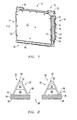
- the removable module assembly 10 has a main body 12 that generally includes two opposing, vertical mounting edges 14,16 and a connection edge 18. At least one of the mounting edges 14, 16 of the removable mounting assembly 10 has an opening 20 to vent by receiving or passing a cooling air flow F into or from an interior cavity 22 of the main body or housing 12 of the removable module assembly 10.
- the cooling air flow F is to flow across the electronic circuitry within the removable module assembly 10 and provide a cooling environment.
- the air flow F can exit the interior of the removable module assembly 10 either through a portion of the opening 20 if there is a U-shaped air flow path within the module 10 or else be vented through another opening in an opposite mounting edge 16 or other vents formed in the main body 12 of the module 10.
- the electronic rack or main chassis unit M has at least one and preferably a pair of separated and opposing module mounting assemblies or walls 24, 26 adapted to receive and secure a compatible removable module 10 with a single module mounting assembly or wall 24 or between the opposing module mounting assemblies or walls 24, 26. At least one of the pair of the opposing module mounting assemblies or walls 24, 26 of the electronics rack M includes a plenum means 28 having an opening 30 for communicating the cooling air flow F to provide a cooling environment for the electronics contained within the removable module 10.
- the module mounting wall or assembly 24, 26 of the main chassis unit M further includes a removable seal plate member 32 having a base plate 34 for securing to the module mounting wall or assembly 24, 26 and an affixed elastomeric and resilient seal member 36 surrounding an opening 38 formed through the base plate 34 and extending from a surface 40 of the base plate 34.
- the seal member or rubber bellows 36 forms a sealing air dam or duct about the cooling air flow F communicated through the plenum 28 of the module mounting assembly 24, 26.
- the module mounting assembly 24, 26 also includes a pair of guide rails 42a, 42b extending from the module mounting assembly 24, 26 forming a U-shaped channel 44 between the pair of guide rails 42a, 42b for receiving one of the mounting edges 64, 66 of the removable module assembly 10.
- the U-shaped channel 44 is preferably sized to be compatible for receiving the corresponding mounting edge 64, 66 of the module 10.
- the sliding air seals 36 must work under a variety of conditions.
- the air seals 36 must operate in a wide variety of temperatures and exposure to corrosive materials. They also must resist tearing when the electronics module 10 is installed and not fail under compressive loads.
- the optionally removable seal plate member 32 incorporates a metal base plate 34 having a slot opening 38 for the air passage F down the center and an inclined upper surface 40 with respect to a lower surface 46; a double layer of elastomeric material 48, 50 having two durometer values, layered one on top of the other, that may be either fully or partially coated with a low friction material 52, such as Teflon® or the like, on at least a portion of the upper elastomeric material 50 to facilitate low friction when an electronics module 10 having a mating tapered surface 70 is slid over and compresses the seal 36.
- a low friction material 52 such as Teflon® or the like
- the elastomeric material 48, 50 is formed having a tapered cross-section as shown in Fig. 8 with the top of the seal 84 in cross section being narrower than the base of the seal 86, and the sides in cross section sloping from the seal top 84 toward the wider seal base 86.
- the rubber bellows or air seal member 36 may be vulcanized to the metal frame or plate member 34.
- the known cooling systems for removable electronic units 10 also use silicone as the material for the seals that can be damaged by exposure to solvents and petro-chemical agents.
- the present invention addresses this shortcoming by using new materials, such as a double layer of fluorosilicone material or other environmentally resistant material having two durometer values, and the removable design to facilitate ease of manufacture.
- the seal plate member 34 is preferably removable and includes a mounting tongue or tang 54 at one end 56 and having an opposing end 58 adapted to be secured to the compatible module mounting assembly 24, 26 with a removable fastener 60, such as a screw or other known fastening means cooperating with the module mounting assembly 24, 26, and the module mounting assembly 24, 26 includes a receptacle 62 adapted to receive the finger 54 of the removable seal plate member 34.
- the known cooling systems for removable electronic units having air flow through electronics modules 10 do not provide a fixed boundary condition at the rack/module interface. The lack of this condition may cause excessive motion of the module 10 during vibration. This motion can produce fretting corrosion at the module-to-rack connector interface as well as electrical noise in sensitive electronics.
- the vibration in the removable module 10 originates externally to the chassis M such as when the device D is mounted within an aircraft.
- the vibration is transmitted into the chassis M that then mechanically conveys the vibration into a mounted or connected module 10.
- the known electronics module designs include a wedge shaped sealing surface, one that is wider at the top and narrower at the bottom near the connector interface at the connector edge 18. This taper causes misalignment and jamming of the module 10 in the rack M during installation. This condition can cause physical damage to the air seal and module sealing surface.
- the present invention is a combined air seal, guide system, and retention method for containing cooling air between equipment racks M and electronics modules 10.
- the guide system on the electronics module provides alignment between the electronics rack or chassis M and the electronic module 10 and provides protection of the sealing surfaces on the electronics module 10.
- the guide system G is accomplished by positioning preferably two ribs 64, 66 on the module 10 to flank the air seal 36 which is installed in the electronics rack or main chassis M.
- the electronics rack or main chassis housing M also contains guide rails 42a, 42b to align the module M and provide a clamping surface 68.
- the module ribs 64, 66 are designed to be a constant distance from the rack M which reduces the misalignment that is present in the known systems for cooling removable electronic units 10 that use a tapered surface.
- the ribs 64, 66 also protrude beyond the module 10 sealing surface 70 thus protecting the surface 70 from objects that could damage the surface 70.
- the retention or latching mechanism 72 for the module 10 within the main chassis M is accomplished by using a wedgelock or latch mechanism 74.
- the wedgelock 74 is tightened using the fastener or lever arm 76 at the top of the removable module 10. It thus provides a fixed structural boundary condition at the compatible and corresponding module-rack interface 24, 26 by clamping the module 10 to the rack or chassis M.
- the fixed boundary condition provides a robust design for use in high vibration applications by preventing motion of the electronics module 10 that could compromise connector interface or the air seal integrity.
- wedgelock type 74 of latching or locking mechanism 72 minimizes undesirable motion in the removable module 10 caused by vibration.
- RF modules 10 require stiff structures and fixed boundary interface conditions.
- wedgelocks 74 historically have provided the best option for achieving minimal motion during dynamic conditions.
- connection edge 18 and the electro-optical connector or plug 80 can be formed or merged with one of the mounting edges 14, 16.
- the interconnecting plug 80 may also function as one of the ribs 64, 66.
- Vibration within an electronic device D of the type including a main chassis unit or electronics rack M and at least one compatible and removable module assembly 10 mountable with the main chassis unit M for supporting electronic circuitry components 78 electro-optically coupled with the main chassis unit M and the removable module assembly 10 that is being cooled by a cooling air flow F from the main chassis unit M about the electronic circuitry 78 can be reduced by mounting of attaching the removable module assembly 10 to at least one module mounting assembly 24 or else preferably between a pair of separated and opposing module mounting assemblies 24, 26 of the main chassis unit M.
- the removable module assembly 10 is ruggedized by the present invention to increase the natural frequency of the removable module 10.
- the removable module assembly 10 has a main body 12 that generally includes two opposing mounting edges 14, 16 and a connection edge 18 as described above. At least one of the mounting edges 14, 16 of the removable mounting assembly 10 includes an opening 20 or other means to vent the cooling air flow F into an interior cavity 22 of the main body or housing 12 of the removable module assembly 10 from the main chassis unit M.
- At least one of the preferred pair of the opposing module mounting assemblies 24, 26 includes a plenum means 28 having an opening 30 for communicating the cooling air flow F into the module 10.
- the module mounting assembly 24, 26 of the main chassis unit or electronics rack M further includes a seal plate member 32 that is preferably removable having a base plate 34 for securing to the module mounting assembly 24 of the main chassis unit M and an affixed elastomeric and resilient seal member 36 that is surrounding an opening 38 formed through the base plate 34 and extending from a surface 40 of the base plate 38.
- the seal member 32 forms a sealing air dam about the cooling air flow F communicated through the plenum 28 of the module mounting assembly 24 of the main chassis unit M.
- the module mounting assembly 24 of the main chassis unit M also includes a pair of guide rails 42a, 42b extending from the module mounting assembly 24 of the main chassis unit M forming a U-shaped channel 44 between the pair of guide rails 42a, 42b for receiving one of the mounting edges 14, 16 of the removable module assembly 10.
- One of the mounting edges 14, 16 of the removable module assembly 10 is positioned within the compatibly formed U-shaped channel 44. The mounting edge so positioned is then placed or maneuvered into contact with a top or upper surface 84 of the compressible and resilient seal 32 to form a sealed passageway or channel between the plenum 28 and the opening 20 for the air flow F to pass through from the electronics rack member M to the interior 22 of the module 10.
- the removable module assembly 10 further preferably includes latch means 72 for securing the removable module assembly 10 to the module mounting assembly 24 of the main chassis unit or electronics rack M.
- the removable module assembly 10 is then secured using the latch means 72 to a corresponding module mounting assembly 24 by locking one of the mounting edges of the removable module assembly 10 within the U-shaped channel 44.
Landscapes
- Engineering & Computer Science (AREA)
- Microelectronics & Electronic Packaging (AREA)
- Aviation & Aerospace Engineering (AREA)
- Physics & Mathematics (AREA)
- Thermal Sciences (AREA)
- Cooling Or The Like Of Electrical Apparatus (AREA)
Applications Claiming Priority (2)
| Application Number | Priority Date | Filing Date | Title |
|---|---|---|---|
| US3430008P | 2008-03-06 | 2008-03-06 | |
| US12/060,719 US7995346B2 (en) | 2008-03-06 | 2008-04-01 | Ruggedized, self aligning, sliding air seal for removable electronic units |
Publications (3)
| Publication Number | Publication Date |
|---|---|
| EP2106205A2 true EP2106205A2 (fr) | 2009-09-30 |
| EP2106205A3 EP2106205A3 (fr) | 2009-10-21 |
| EP2106205B1 EP2106205B1 (fr) | 2017-01-11 |
Family
ID=40756335
Family Applications (1)
| Application Number | Title | Priority Date | Filing Date |
|---|---|---|---|
| EP09002127.0A Ceased EP2106205B1 (fr) | 2008-03-06 | 2009-02-16 | Joint d'étanchéité à l'air durci et à alignement automatique pour unités électroniques amovibles |
Country Status (1)
| Country | Link |
|---|---|
| EP (1) | EP2106205B1 (fr) |
Cited By (5)
| Publication number | Priority date | Publication date | Assignee | Title |
|---|---|---|---|---|
| FR2981824A1 (fr) * | 2011-10-20 | 2013-04-26 | Airbus Operations Sas | Equipement avionique |
| WO2016189351A1 (fr) | 2015-05-25 | 2016-12-01 | Aselsan Elektronik Sanayi Ve Ticaret Anonim Sirketi | Dispositif de refroidissement étanche à l'eau |
| US20230349649A1 (en) * | 2022-04-27 | 2023-11-02 | Eagle Technology, Llc | Sealing retainer to be coupled between chassis and electronic module and associated method |
| US11895806B2 (en) | 2022-04-27 | 2024-02-06 | Eagle Technology, Llc | Electronic assembly having sealing retainer coupling an electronic module and associated method |
| US12225679B2 (en) | 2022-05-06 | 2025-02-11 | Eagle Technology, Llc | Electronic assembly having sealing retainer coupling an electronic module and associated method |
Citations (5)
| Publication number | Priority date | Publication date | Assignee | Title |
|---|---|---|---|---|
| US2843806A (en) | 1955-04-29 | 1958-07-15 | Hughes Aircraft Co | Cross-cooled cabinet for electrical equipment |
| US3956673A (en) | 1974-02-14 | 1976-05-11 | Lockheed Aircraft Corporation | Printed circuit modules cooled by rack with forced air |
| US4006388A (en) | 1975-03-03 | 1977-02-01 | Hughes Aircraft Company | Thermally controlled electronic system package |
| US4277815A (en) | 1979-06-15 | 1981-07-07 | Westinghouse Electric Corp. | Replaceable air seal for force cooled removable electronic units |
| US4375290A (en) | 1980-11-24 | 1983-03-01 | Westinghouse Electric Corp. | Sliding compression air seal for removable electronic units |
Family Cites Families (3)
| Publication number | Priority date | Publication date | Assignee | Title |
|---|---|---|---|---|
| US4442475A (en) * | 1982-07-06 | 1984-04-10 | The United States Of America As Represented By The Secretary Of The Navy | Tapered seal for flow-through module |
| US5034852A (en) * | 1989-11-06 | 1991-07-23 | Raytheon Company | Gasket for a hollow core module |
| US7180737B2 (en) * | 2004-12-20 | 2007-02-20 | Harris Corporation | Heat exchanger system for circuit card assemblies |
-
2009
- 2009-02-16 EP EP09002127.0A patent/EP2106205B1/fr not_active Ceased
Patent Citations (5)
| Publication number | Priority date | Publication date | Assignee | Title |
|---|---|---|---|---|
| US2843806A (en) | 1955-04-29 | 1958-07-15 | Hughes Aircraft Co | Cross-cooled cabinet for electrical equipment |
| US3956673A (en) | 1974-02-14 | 1976-05-11 | Lockheed Aircraft Corporation | Printed circuit modules cooled by rack with forced air |
| US4006388A (en) | 1975-03-03 | 1977-02-01 | Hughes Aircraft Company | Thermally controlled electronic system package |
| US4277815A (en) | 1979-06-15 | 1981-07-07 | Westinghouse Electric Corp. | Replaceable air seal for force cooled removable electronic units |
| US4375290A (en) | 1980-11-24 | 1983-03-01 | Westinghouse Electric Corp. | Sliding compression air seal for removable electronic units |
Cited By (6)
| Publication number | Priority date | Publication date | Assignee | Title |
|---|---|---|---|---|
| FR2981824A1 (fr) * | 2011-10-20 | 2013-04-26 | Airbus Operations Sas | Equipement avionique |
| WO2016189351A1 (fr) | 2015-05-25 | 2016-12-01 | Aselsan Elektronik Sanayi Ve Ticaret Anonim Sirketi | Dispositif de refroidissement étanche à l'eau |
| US20230349649A1 (en) * | 2022-04-27 | 2023-11-02 | Eagle Technology, Llc | Sealing retainer to be coupled between chassis and electronic module and associated method |
| US11895806B2 (en) | 2022-04-27 | 2024-02-06 | Eagle Technology, Llc | Electronic assembly having sealing retainer coupling an electronic module and associated method |
| US12066257B2 (en) * | 2022-04-27 | 2024-08-20 | Eagle Technology, Llc | Sealing retainer to be coupled between chassis and electronic module and associated method |
| US12225679B2 (en) | 2022-05-06 | 2025-02-11 | Eagle Technology, Llc | Electronic assembly having sealing retainer coupling an electronic module and associated method |
Also Published As
| Publication number | Publication date |
|---|---|
| EP2106205A3 (fr) | 2009-10-21 |
| EP2106205B1 (fr) | 2017-01-11 |
Similar Documents
| Publication | Publication Date | Title |
|---|---|---|
| US7995346B2 (en) | Ruggedized, self aligning, sliding air seal for removable electronic units | |
| US7515413B1 (en) | Fan field replaceable unit | |
| US5034852A (en) | Gasket for a hollow core module | |
| US9426931B2 (en) | Fluid-flow-through cooling of circuit boards | |
| CN110536584B (zh) | 用于it和数据中心液体冷却的高可靠性冷却模块设计 | |
| US6621706B2 (en) | Utilizing a convection cooled electronic circuit card for producing a conduction cooled electronic card module | |
| US9974157B2 (en) | Circuit card cartridge for an electronic system | |
| EP2106205B1 (fr) | Joint d'étanchéité à l'air durci et à alignement automatique pour unités électroniques amovibles | |
| US8517678B2 (en) | Heat dissipating assembly | |
| US6660932B1 (en) | Dynamically moveable exhausting EMC sealing system | |
| US6794571B1 (en) | EMC sealing system and method for an electrical enclosure | |
| CN108933391B (zh) | 电力管理面板和控制器组件 | |
| US20030053295A1 (en) | Heat dissipation device retention assembly | |
| US6491528B1 (en) | Method and apparatus for vibration and temperature isolation | |
| CN210155600U (zh) | 一种基于mtca标准的加固密封机箱 | |
| EP2926636B1 (fr) | Technologie de refroidissement par circulation d'air et modules de carte à circuits imprimés à circulation d'air | |
| US7957138B2 (en) | System and method for blocking lateral airflow paths between modules in an electronic equipment enclosure | |
| US4520426A (en) | Cooling subrack for logic cards | |
| JPH07131173A (ja) | 電子機器 | |
| EP4284134A1 (fr) | Ensemble électronique à surfaces de glissement et procédés associés | |
| US12225679B2 (en) | Electronic assembly having sealing retainer coupling an electronic module and associated method | |
| CN115047942A (zh) | 一种风冷密封式加固计算机 | |
| JPS5844638Y2 (ja) | プリント配線板の実装構造 | |
| CN222582855U (zh) | 一种车载一体化电磁屏蔽机箱 | |
| US11825633B2 (en) | Circuit card assembly (CCA) module thermal interface devices |
Legal Events
| Date | Code | Title | Description |
|---|---|---|---|
| PUAI | Public reference made under article 153(3) epc to a published international application that has entered the european phase |
Free format text: ORIGINAL CODE: 0009012 |
|
| PUAL | Search report despatched |
Free format text: ORIGINAL CODE: 0009013 |
|
| AK | Designated contracting states |
Kind code of ref document: A2 Designated state(s): AT BE BG CH CY CZ DE DK EE ES FI FR GB GR HR HU IE IS IT LI LT LU LV MC MK MT NL NO PL PT RO SE SI SK TR |
|
| AX | Request for extension of the european patent |
Extension state: AL BA RS |
|
| AK | Designated contracting states |
Kind code of ref document: A3 Designated state(s): AT BE BG CH CY CZ DE DK EE ES FI FR GB GR HR HU IE IS IT LI LT LU LV MC MK MT NL NO PL PT RO SE SI SK TR |
|
| AX | Request for extension of the european patent |
Extension state: AL BA RS |
|
| RIC1 | Information provided on ipc code assigned before grant |
Ipc: H05K 7/20 20060101ALI20090914BHEP Ipc: H05K 7/14 20060101AFI20090623BHEP |
|
| 17P | Request for examination filed |
Effective date: 20100416 |
|
| AKX | Designation fees paid |
Designated state(s): DE FR GB |
|
| 17Q | First examination report despatched |
Effective date: 20150109 |
|
| GRAP | Despatch of communication of intention to grant a patent |
Free format text: ORIGINAL CODE: EPIDOSNIGR1 |
|
| INTG | Intention to grant announced |
Effective date: 20160812 |
|
| GRAS | Grant fee paid |
Free format text: ORIGINAL CODE: EPIDOSNIGR3 |
|
| STAA | Information on the status of an ep patent application or granted ep patent |
Free format text: STATUS: GRANT OF PATENT IS INTENDED |
|
| GRAA | (expected) grant |
Free format text: ORIGINAL CODE: 0009210 |
|
| STAA | Information on the status of an ep patent application or granted ep patent |
Free format text: STATUS: THE PATENT HAS BEEN GRANTED |
|
| AK | Designated contracting states |
Kind code of ref document: B1 Designated state(s): DE FR GB |
|
| REG | Reference to a national code |
Ref country code: GB Ref legal event code: FG4D |
|
| REG | Reference to a national code |
Ref country code: FR Ref legal event code: PLFP Year of fee payment: 9 |
|
| REG | Reference to a national code |
Ref country code: DE Ref legal event code: R096 Ref document number: 602009043633 Country of ref document: DE |
|
| REG | Reference to a national code |
Ref country code: DE Ref legal event code: R097 Ref document number: 602009043633 Country of ref document: DE |
|
| PLBE | No opposition filed within time limit |
Free format text: ORIGINAL CODE: 0009261 |
|
| STAA | Information on the status of an ep patent application or granted ep patent |
Free format text: STATUS: NO OPPOSITION FILED WITHIN TIME LIMIT |
|
| 26N | No opposition filed |
Effective date: 20171012 |
|
| REG | Reference to a national code |
Ref country code: FR Ref legal event code: PLFP Year of fee payment: 10 |
|
| P01 | Opt-out of the competence of the unified patent court (upc) registered |
Effective date: 20230607 |
|
| PGFP | Annual fee paid to national office [announced via postgrant information from national office to epo] |
Ref country code: DE Payment date: 20240219 Year of fee payment: 16 Ref country code: GB Payment date: 20240219 Year of fee payment: 16 |
|
| PGFP | Annual fee paid to national office [announced via postgrant information from national office to epo] |
Ref country code: FR Payment date: 20240221 Year of fee payment: 16 |
|
| REG | Reference to a national code |
Ref country code: DE Ref legal event code: R119 Ref document number: 602009043633 Country of ref document: DE |
|
| GBPC | Gb: european patent ceased through non-payment of renewal fee |
Effective date: 20250216 |
|
| PG25 | Lapsed in a contracting state [announced via postgrant information from national office to epo] |
Ref country code: DE Free format text: LAPSE BECAUSE OF NON-PAYMENT OF DUE FEES Effective date: 20250902 |
|
| PG25 | Lapsed in a contracting state [announced via postgrant information from national office to epo] |
Ref country code: GB Free format text: LAPSE BECAUSE OF NON-PAYMENT OF DUE FEES Effective date: 20250216 |
|
| PG25 | Lapsed in a contracting state [announced via postgrant information from national office to epo] |
Ref country code: FR Free format text: LAPSE BECAUSE OF NON-PAYMENT OF DUE FEES Effective date: 20250228 |