EP2106206A2 - Dispositif de refroidissement pour carte de circuit imprimé intégrée dans un châssis - Google Patents
Dispositif de refroidissement pour carte de circuit imprimé intégrée dans un châssis Download PDFInfo
- Publication number
- EP2106206A2 EP2106206A2 EP09155607A EP09155607A EP2106206A2 EP 2106206 A2 EP2106206 A2 EP 2106206A2 EP 09155607 A EP09155607 A EP 09155607A EP 09155607 A EP09155607 A EP 09155607A EP 2106206 A2 EP2106206 A2 EP 2106206A2
- Authority
- EP
- European Patent Office
- Prior art keywords
- space
- circuit board
- printed circuit
- sidewall
- cooling device
- Prior art date
- Legal status (The legal status is an assumption and is not a legal conclusion. Google has not performed a legal analysis and makes no representation as to the accuracy of the status listed.)
- Granted
Links
Images



Classifications
-
- H—ELECTRICITY
- H05—ELECTRIC TECHNIQUES NOT OTHERWISE PROVIDED FOR
- H05K—PRINTED CIRCUITS; CASINGS OR CONSTRUCTIONAL DETAILS OF ELECTRIC APPARATUS; MANUFACTURE OF ASSEMBLAGES OF ELECTRICAL COMPONENTS
- H05K7/00—Constructional details common to different types of electric apparatus
- H05K7/20—Modifications to facilitate cooling, ventilating, or heating
- H05K7/20709—Modifications to facilitate cooling, ventilating, or heating for server racks or cabinets; for data centers, e.g. 19-inch computer racks
- H05K7/20718—Forced ventilation of a gaseous coolant
- H05K7/20727—Forced ventilation of a gaseous coolant within server blades for removing heat from heat source
Definitions
- the present invention relates to a computer device or electronic device having a cooling device that cools a printed circuit board while accommodating the printed circuit board in a chassis, and to the cooling device itself.
- a computer device such as a rack mount type server is well known.
- the computer device includes a front panel rising from a front end of a bottom plate and a rear panel rising from a rear end.
- a hollow is partitioned (an interior space is formed) from the front panel toward the rear panel on the bottom plate.
- the printed circuit board is extended (is located) along the bottom plate in the hollow.
- an air flow is produced along a surface of the printed circuit board from the front panel toward the rear panel.
- Japanese Laid-open Patent Publication Nos. 4-15998 , 2003-283171 , and 2000-40474 discuss apparatuses wherein the air flow cools electronic parts mounted on the surface of the printed circuit board.
- a device e.g., cooling device, or a computer/electronic device including cooling means
- a chassis that partitions (includes an internal structure which defines), or at least encloses, a first space, a second space, and a third space sandwiched between the first space and the second space, a printed circuit board accommodated in the chassis that extends from the first space to the second space while traversing the third space, a fan occupying the third space outside a predetermined space that produces an air flow from the first space toward the second space by rotation of a rotor blade, wherein the predetermined space is ensured between the printed circuit board and the fan in the third space and an air duct member that occupies the predetermined space to form a flow passage of the air flow from an intake port to an exhaust port on the printed circuit board, wherein the intake port is opened to (is an opening into) the second space and the exhaust port is opened to (is an opening into) the first space.
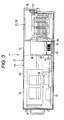
- FIG. 1 depicts an appearance of a rack mount type computer device 11.
- the computer device 11 includes a chassis 12.
- the chassis 12 has a generally box shape with a bottom plate, side plates, a top or ceiling plate, and front and rear panels, and defines within it an interior space enclosed by these plates/panels. Openings in the front and rear panels connect the interior space with the outside permitting a flow of air therethrough.
- the chassis 12 partitions a hollow extended from a front-side opening 14 toward a rear-side opening 15 on a rectangular bottom plate 13.
- the hollow is formed by a rectangular-solid space.
- the bottom plate 13 partitions a bottom surface of the rectangular-solid space.
- the front-side opening 14 and the rear-side opening 15 define a front face and a rear face of the rectangular-solid space.
- a pair of side faces of the rectangular-solid space is partitions by side plates 17.
- the side plates 17 extend from the front-side opening 14 to the rear-side opening 15 while facing each other.
- a lower end of the side plate 17 is connected to the bottom plate 13.
- a ceiling surface of the rectangular-solid space is partitioned by a ceiling plate 18.
- the ceiling plate 18 extends from the front-side opening 14 to the rear-side opening 15 while facing the bottom plate 13.
- the ceiling plate 18 may be partitioned in a longitudinal direction.
- the front-side opening 14 is covered with a front panel 21.
- the rear-side opening 15 is covered with a rear panel 22. Grilled windows 23 for air supply and exhaust are formed in the front panel 21 and the rear panel 22.
- the interior space (rectangular-solid space 24) within the chassis 12 is divided up (partitioned) into distinct spaces by internal walls of the chassis and/or by other internal structure of the device 11.
- a rectangular-solid first space 25 is formed adjacent to the front-side opening 14 in a rectangular-solid space 24.
- a second space 26 is formed adjacent to the rear-side opening 15 in the rectangular-solid space 24.
- a third space 27 is blocked out (indicated by dashed lines) between the first space 25 and the second space 26.
- the third space 27 is sandwiched between the first space 25 and the second space 26. That is, starting from the front panel, the interior space within the chassis is taken up by the first space 25, third space 27, and second space 26 in that order.
- the rectangular-solid space 24 is sequentially partitioned from the front face by the first space 25, the third space 27, and the second space 26.
- Electronic parts having relatively low profiles are accommodated in the first space 25.
- the low-profile electronic parts include a CPU (Central Processing Unit) chip package 28 and a controller chip package 29.
- the CPU chip package 28 and the controller chip package 29 include heat sinks.
- the heat sink includes plural cooling fins. Each cooling fin is extended in parallel with the side face of the rectangular-solid space 24.
- a memory module group 31 and a PCI (Peripheral Component Interconnect) card group 32 are accommodated in the second space 26.
- a tray 33 is disposed between the side plates 17.
- the tray 33 extends from one of the side plates 17 to the other side plate 17 in parallel with the bottom surface of the rectangular-solid space 24. Both ends of the tray 33 are fixed to the side plates 17, respectively.
- the tray 33 is fixed to the side plates 17 with rivets.
- the tray 33 partitions the third space 27 into an upper-side first small space 34 and a lower-side second small space 35.
- a fan unit 36 is disposed in the first small space 34.
- the fan unit 36 is mounted on the tray 33.
- the fan unit 36 occupies the first small space 34.
- the fan unit 36 separates the first space from the second space, in other words it partitions the first space 25 and the second space 26 on the upper side of the third space 27.
- the fan unit 36 includes plural axial flow fans 37.
- Each axial flow fan 37 is rotated about a rotation shaft 38 extended in parallel with the bottom surface of the rectangular-solid space 24.
- double-axial flow fans 37 having coaxial rotation shafts 38 are disposed in three lines.
- the six axial flow fans 37 are mutually coupled.
- the air flow is produced from the first space 25 toward the second space 26 according to the rotation of the fan, thereby producing the air flow in the device interior (hollow) from the front-side opening 14 toward the rear-side opening 15.
- An air duct member 41 is disposed in the second small space 35.
- the air duct member 41 occupies the second small space 35.
- the air duct member 41 partitions the first space 25 and the second space 26 on the lower side of the third space 27.
- the air duct member 41 is mounted on a printed circuit board 42.
- a flow passage 43 is formed between the air duct member 41 and the printed circuit board 42.
- the printed circuit board 42 extends from the first space 25 to the second space 26 while traversing the third space 27 in the chassis 12. It is preferable that the printed circuit board 42 be extended in parallel with the bottom surface of the rectangular-solid space 24.
- the CPU chip package 28 and the controller chip package 29 are mounted on the printed circuit board 42.
- the memory module group 31 and the PCI card group 32 are mounted on the printed circuit board 42.
- the electronic parts are mounted on the surface of the printed circuit board 42.
- the electronic parts include predetermined semiconductor chip packages 44.
- the semiconductor chip package 44 has a heat release value that is equal to or lower than that of the CPU chip package 28 or controller chip package 29.
- the semiconductor chip package 44 includes the heat sink.
- the heat sink includes plural cooling fins. Each cooling fin is extended in parallel with the front or rear of the rectangular-solid space 24.
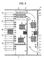
- the air duct member 41 includes a first sidewall 47.
- the first sidewall 47 rises from the surface of the printed circuit board 42, and the first sidewall 47 extends along a boundary surface between the first space 25 and the third space 27. That is, the first sidewall 47 divides the first space from the second small space; in other words it partitions the first space 25 and the second small space 35.
- the air duct member 41 includes a second sidewall 48.
- the second sidewall 48 rises from the surface of the printed circuit board 42, and the second sidewall 48 extends along a boundary surface between the second space 26 and the third space 27. That is, the second sidewall 48 partitions (separates) the second small space 35 and the second space 26.
- An upper end of the first sidewall 47 and an upper end of the second sidewall 48 are connected to each other by a ceiling plate 49. That is, similar to the tray 33, the ceiling plate 49 partitions the first small space 34 and the second small space 35.
- the ceiling plate 49 extends from the upper end of the first sidewall 47 to the upper end of the second sidewall 48.
- the first sidewall 47, the second sidewall 48, and the ceiling plate 49 traverse the printed circuit board 42.
- the first sidewall 47, the second sidewall 48, and the ceiling plate 49 are formed by, for example, one plate member (for example, a U-shaped integral metal sheet).
- the plate member is made of stainless steel.
- the first sidewall 47, the second sidewall 48, and the ceiling plate 49 are divided from one end to the other end into a first divided region (division) 51, a second divided region (division) 52, and a third divided region (division) 53.
- the exhaust port 54 is formed in the first sidewall 47.
- the exhaust port 54 is formed based on cooperation with a notch formed in an edge of the plate member and the printed circuit board 42.
- an intake port 55 is formed in the second sidewall 48.
- the intake port 55 is formed based on cooperation with a notch partitioned in an edge of the plate member and the printed circuit board 42.
- a flow passage from the intake port 55 to the exhaust port 54 passes through the third divided region 53, the second divided region 52, and the first divided region 51.
- the flow passage is extended in parallel with the front face of the rectangular-solid space 24 and traverses the printed circuit board 42.
- the air flow is produced from the first space 25 toward the second space 26. That is, air is caused to flow from the first space to the second space.
- the heat sinks of the CPU chip package 28 and the controller chip package 29 are exposed to the air flow.
- the air flow deprives the heat sink of the heat.
- the CPU chip package 28 and the controller chip package 29 are cooled, so that a temperature rise is restrained in the CPU chip package 28 and the controller chip package 29.
- the air pressure in the first space 25 is reduced according to the operation of the axial flow fan 37.
- a pressure in the second space 26 is increased.
- the increase in pressure of the second space 26 is released through the grilled window 23 of the rear panel 22 or the intake port 55 of the air duct member 41. That is, in the air duct member 41, the air flow is produced from the intake port 55 toward the exhaust port 54.
- the air flow is produced along the flow passage in the air duct member 41.
- the heat sink of the semiconductor chip package 44 is exposed to the air flow.
- the air flowing past the heat sink is warmed, thereby carrying away part of its heat; in other words the air flow deprives the heat sink of the heat.
- the semiconductor chip package 44 disposed in the flow passage 43 in the air duct member 41 is cooled, so that a temperature rise is restrained in the semiconductor chip package 44.
- the second small space 35 is ensured (defined) between the fan unit 36 and the printed circuit board 42.
- electronic parts such as the semiconductor chip package 44 are mounted on the printed circuit board 42.
- the area where the electronic parts are mounted is not reduced irrespective of the disposition of the fan unit 36.
- the area where the electronic parts are mounted on the printed circuit board 42 is effectively used.
- the electronic parts are exposed to the air flow although the electronic parts are disposed between the fan unit 36 and the printed circuit board 41, so that a temperature rise is restrained in the electronic parts.
Landscapes
- Engineering & Computer Science (AREA)
- Computer Hardware Design (AREA)
- General Engineering & Computer Science (AREA)
- Physics & Mathematics (AREA)
- Thermal Sciences (AREA)
- Microelectronics & Electronic Packaging (AREA)
- Cooling Or The Like Of Electrical Apparatus (AREA)
Applications Claiming Priority (1)
| Application Number | Priority Date | Filing Date | Title |
|---|---|---|---|
| JP2008087529A JP4930429B2 (ja) | 2008-03-28 | 2008-03-28 | 収容したプリント基板を冷却する装置 |
Publications (3)
| Publication Number | Publication Date |
|---|---|
| EP2106206A2 true EP2106206A2 (fr) | 2009-09-30 |
| EP2106206A3 EP2106206A3 (fr) | 2012-02-22 |
| EP2106206B1 EP2106206B1 (fr) | 2013-07-31 |
Family
ID=40756339
Family Applications (1)
| Application Number | Title | Priority Date | Filing Date |
|---|---|---|---|
| EP09155607.6A Expired - Fee Related EP2106206B1 (fr) | 2008-03-28 | 2009-03-19 | Dispositif de refroidissement pour carte de circuit imprimé intégrée dans un châssis |
Country Status (4)
| Country | Link |
|---|---|
| US (1) | US7864523B2 (fr) |
| EP (1) | EP2106206B1 (fr) |
| JP (1) | JP4930429B2 (fr) |
| CN (1) | CN101547588B (fr) |
Families Citing this family (24)
| Publication number | Priority date | Publication date | Assignee | Title |
|---|---|---|---|---|
| CN101516166B (zh) * | 2008-02-22 | 2010-12-08 | 华为技术有限公司 | 一种横插框及通信机柜 |
| TWI426860B (zh) * | 2009-11-20 | 2014-02-11 | Delta Electronics Inc | 熱交換裝置及應用熱交換裝置的密閉式電器設備 |
| CN102193589A (zh) * | 2010-03-15 | 2011-09-21 | 英业达股份有限公司 | 服务器辅助运算系统 |
| US8045328B1 (en) * | 2010-05-04 | 2011-10-25 | Chenbro Micom Co., Ltd. | Server and cooler moduel arrangement |
| US8400765B2 (en) | 2010-09-20 | 2013-03-19 | Amazon Technologies, Inc. | System with air flow under data storage devices |
| CN102541154A (zh) * | 2010-12-08 | 2012-07-04 | 鸿富锦精密工业(深圳)有限公司 | 机架式服务器 |
| US20120243177A1 (en) * | 2011-03-21 | 2012-09-27 | Hamilton Sundstrand Corporation | Indirect bleed air cooling of a fan motor controller |
| TW201314425A (zh) * | 2011-09-30 | 2013-04-01 | 鴻海精密工業股份有限公司 | 散熱裝置及使用該散熱裝置的電子裝置 |
| US20130294026A1 (en) * | 2012-05-07 | 2013-11-07 | Abb Oy | Electronics compartment |
| US9167730B2 (en) * | 2012-05-07 | 2015-10-20 | Abb Technology Oy | Electronics compartment |
| CN103687414B (zh) * | 2012-08-30 | 2016-12-21 | 台达电子工业股份有限公司 | 大功率机柜散热系统及静止无功补偿系统 |
| USD733118S1 (en) * | 2013-11-27 | 2015-06-30 | GDC Technology Limited | Data storage device |
| USD745867S1 (en) * | 2015-10-01 | 2015-12-22 | Revolution Display, Llc | Rack mount server |
| CN105487619A (zh) * | 2015-11-24 | 2016-04-13 | 英业达科技有限公司 | 电子装置 |
| WO2018032313A1 (fr) * | 2016-08-16 | 2018-02-22 | 陈玮彤 | Boîtier de dissipation de chaleur pour ordinateur |
| JP2018074102A (ja) * | 2016-11-04 | 2018-05-10 | 富士通株式会社 | 電子装置 |
| US11102910B2 (en) * | 2017-08-01 | 2021-08-24 | Dell Products L.P. | Flexible service air baffle |
| CN107831806A (zh) * | 2017-11-03 | 2018-03-23 | 江苏恒达微波技术开发有限公司 | 一种新型的通信基站柜 |
| US10692793B2 (en) | 2018-03-02 | 2020-06-23 | Micron Technology, Inc. | Electronic device with a package-level thermal regulator mechanism and associated systems, devices, and methods |
| US10834853B2 (en) * | 2018-03-02 | 2020-11-10 | Micron Technology, Inc. | Electronic device with a card-level thermal regulator mechanism and associated systems, devices, and methods |
| US11178796B2 (en) * | 2018-09-26 | 2021-11-16 | Rockwell Automation Technologies, Inc. | Power conversion equipment cooling with cyclonic airborne particle reduction |
| JP7298254B2 (ja) * | 2019-04-10 | 2023-06-27 | 富士通株式会社 | 電子機器及び電子ユニット |
| US11564325B2 (en) * | 2021-03-09 | 2023-01-24 | Quanta Computer Inc. | System chassis with raised sliding channel |
| USD1123918S1 (en) * | 2024-03-05 | 2026-04-28 | Bitdeer Semiconductor Technology Pte. Ltd. | Modular liquid cooled server |
Citations (4)
| Publication number | Priority date | Publication date | Assignee | Title |
|---|---|---|---|---|
| JPH0415998A (ja) | 1990-05-10 | 1992-01-21 | Fujitsu Ltd | 電子装置の冷却用ファンの取付け構造 |
| JP2000040474A (ja) | 1998-07-23 | 2000-02-08 | Mitsubishi Electric Corp | プラズマディスプレイパネル及びプラズマディスプレイ装置 |
| JP2003283171A (ja) | 2002-03-22 | 2003-10-03 | Ricoh Co Ltd | 電子回路基板の冷却構造 |
| JP2008087529A (ja) | 2006-09-29 | 2008-04-17 | Mitsubishi Electric Corp | アンダーステア抑制装置 |
Family Cites Families (25)
| Publication number | Priority date | Publication date | Assignee | Title |
|---|---|---|---|---|
| EP0488679A3 (en) * | 1990-11-30 | 1993-08-04 | Fujitsu Limited | Storage disk module and storage disk device having a plurality of storage disk modules |
| US5414591A (en) * | 1991-04-15 | 1995-05-09 | Hitachi, Ltd. | Magnetic disk storage system |
| US5333097A (en) * | 1992-06-18 | 1994-07-26 | Digital Equipment Corporation | Disk drive holder and interconnection system |
| US5822184A (en) * | 1994-07-28 | 1998-10-13 | Rabinovitz; Josef | Modular disk drive assembly operatively mountable in industry standard expansion bays of personal desktop computers |
| US5684671A (en) * | 1995-08-22 | 1997-11-04 | Sequent Computer Systems, Inc. | Packaging architecture for a data server |
| US5816673A (en) * | 1996-10-11 | 1998-10-06 | Sauer; James P. | Computer chassis assembly |
| US5971804A (en) * | 1997-06-30 | 1999-10-26 | Emc Corporation | Backplane having strip transmission line ethernet bus |
| JPH11184570A (ja) * | 1997-12-25 | 1999-07-09 | Hitachi Ltd | 電源を備えた装置 |
| US6115250A (en) * | 1998-01-20 | 2000-09-05 | Dell Usa, Lp | Computer and an assembly and method for cooling a computer |
| US6563706B1 (en) * | 1998-06-23 | 2003-05-13 | Hewlett-Packard Development Company, L.P. | Typically high-availability information storage product |
| AU3962600A (en) * | 1999-03-18 | 2000-10-09 | Fritschle, Simone | Casing with a fan unit and fan unit |
| US6496366B1 (en) * | 1999-10-26 | 2002-12-17 | Rackable Systems, Llc | High density computer equipment storage system |
| JP2001338486A (ja) * | 2000-05-25 | 2001-12-07 | Hitachi Ltd | 情報記憶装置 |
| TW484721U (en) * | 2000-11-06 | 2002-04-21 | Giga Byte Tech Co Ltd | Improved airflow guiding structure of server |
| US6525935B2 (en) * | 2001-03-12 | 2003-02-25 | Appro International, Inc. | Low profile highly accessible computer enclosure with plenum for cooling high power processors |
| JP3513116B2 (ja) * | 2001-03-22 | 2004-03-31 | 株式会社東芝 | 情報処理装置 |
| US6957291B2 (en) * | 2001-03-29 | 2005-10-18 | Quantum Corporation | Removable disk storage array emulating tape library having backup and archive capability |
| JP2002374085A (ja) * | 2001-06-15 | 2002-12-26 | Hitachi Ltd | 密閉型情報処理装置の冷却機構 |
| US6693796B2 (en) * | 2001-09-08 | 2004-02-17 | Hewlett-Packard Development Company, L.P. | Disk drive support apparatus and methods |
| US6665179B2 (en) * | 2002-02-06 | 2003-12-16 | Shin Jiuh Corp. | Blade server module |
| US6839233B2 (en) * | 2003-01-02 | 2005-01-04 | Dell Products L.P. | Removable fan bay |
| JP4896359B2 (ja) * | 2003-01-28 | 2012-03-14 | 富士通株式会社 | 電子装置 |
| JP4322637B2 (ja) * | 2003-11-20 | 2009-09-02 | 株式会社日立製作所 | ディスクアレイ装置 |
| JP2006059448A (ja) * | 2004-08-20 | 2006-03-02 | Hitachi Ltd | ディスクアレイ装置 |
| JP4585325B2 (ja) * | 2005-02-08 | 2010-11-24 | 株式会社日立製作所 | ディスクアレイ装置 |
-
2008
- 2008-03-28 JP JP2008087529A patent/JP4930429B2/ja not_active Expired - Fee Related
-
2009
- 2009-03-18 CN CN200910119032.2A patent/CN101547588B/zh not_active Expired - Fee Related
- 2009-03-19 EP EP09155607.6A patent/EP2106206B1/fr not_active Expired - Fee Related
- 2009-03-27 US US12/412,593 patent/US7864523B2/en not_active Expired - Fee Related
Patent Citations (4)
| Publication number | Priority date | Publication date | Assignee | Title |
|---|---|---|---|---|
| JPH0415998A (ja) | 1990-05-10 | 1992-01-21 | Fujitsu Ltd | 電子装置の冷却用ファンの取付け構造 |
| JP2000040474A (ja) | 1998-07-23 | 2000-02-08 | Mitsubishi Electric Corp | プラズマディスプレイパネル及びプラズマディスプレイ装置 |
| JP2003283171A (ja) | 2002-03-22 | 2003-10-03 | Ricoh Co Ltd | 電子回路基板の冷却構造 |
| JP2008087529A (ja) | 2006-09-29 | 2008-04-17 | Mitsubishi Electric Corp | アンダーステア抑制装置 |
Also Published As
| Publication number | Publication date |
|---|---|
| EP2106206A3 (fr) | 2012-02-22 |
| US7864523B2 (en) | 2011-01-04 |
| CN101547588A (zh) | 2009-09-30 |
| US20090244842A1 (en) | 2009-10-01 |
| EP2106206B1 (fr) | 2013-07-31 |
| JP4930429B2 (ja) | 2012-05-16 |
| CN101547588B (zh) | 2013-02-27 |
| JP2009245977A (ja) | 2009-10-22 |
Similar Documents
| Publication | Publication Date | Title |
|---|---|---|
| EP2106206A2 (fr) | Dispositif de refroidissement pour carte de circuit imprimé intégrée dans un châssis | |
| US8953312B2 (en) | Electronic device and casing for electronic device | |
| JP4735528B2 (ja) | 車載用の電子機器の冷却構造 | |
| US7522413B2 (en) | Heat dissipating system | |
| CN201138463Y (zh) | 具有导风罩的电脑系统 | |
| US6724624B1 (en) | Housing with directed-flow cooling for computer | |
| EP2355639B1 (fr) | Processeur de commande | |
| CN201600636U (zh) | 电子装置壳体 | |
| US12200897B2 (en) | Electronic apparatus, cooling module, and heat sink | |
| JP7836752B2 (ja) | 電子機器の冷却装置 | |
| US8248795B2 (en) | Data center and server module of the same | |
| JP2007047998A (ja) | 電子部品冷却構造及び情報処理装置 | |
| EP2909695B1 (fr) | Dispositif électronique avec combinaison radiateur / dispositif soufflant ou ventilateur possédant une conduite d'air | |
| JP5760796B2 (ja) | 冷却ユニット | |
| EP2890227A1 (fr) | Appareil de conversion de puissance électrique | |
| KR20190008328A (ko) | 전자 기기 | |
| JP7851848B2 (ja) | 電子機器の冷却装置 | |
| US20080055853A1 (en) | Heat dissipating module and assembly of the heat dissipating module and a computer housing | |
| CN103037664A (zh) | 散热装置及使用该散热装置的电子装置 | |
| US20050189088A1 (en) | Circulation structure of heat dissipation device | |
| KR101007241B1 (ko) | 수용된 인쇄 기판을 냉각하는 장치 | |
| KR101438723B1 (ko) | Gpu가 장착된 컴퓨터 보드 냉각 시스템 | |
| CN105700644A (zh) | 散热模组 | |
| US20070243814A1 (en) | Enclosure unit and electronic apparatus | |
| CN223486450U (zh) | 工业计算机 |
Legal Events
| Date | Code | Title | Description |
|---|---|---|---|
| PUAI | Public reference made under article 153(3) epc to a published international application that has entered the european phase |
Free format text: ORIGINAL CODE: 0009012 |
|
| AK | Designated contracting states |
Kind code of ref document: A2 Designated state(s): AT BE BG CH CY CZ DE DK EE ES FI FR GB GR HR HU IE IS IT LI LT LU LV MC MK MT NL NO PL PT RO SE SI SK TR |
|
| AX | Request for extension of the european patent |
Extension state: AL BA RS |
|
| PUAL | Search report despatched |
Free format text: ORIGINAL CODE: 0009013 |
|
| AK | Designated contracting states |
Kind code of ref document: A3 Designated state(s): AT BE BG CH CY CZ DE DK EE ES FI FR GB GR HR HU IE IS IT LI LT LU LV MC MK MT NL NO PL PT RO SE SI SK TR |
|
| AX | Request for extension of the european patent |
Extension state: AL BA RS |
|
| RIC1 | Information provided on ipc code assigned before grant |
Ipc: H05K 7/20 20060101AFI20120119BHEP |
|
| 17P | Request for examination filed |
Effective date: 20120816 |
|
| AKX | Designation fees paid |
Designated state(s): DE FR GB |
|
| GRAP | Despatch of communication of intention to grant a patent |
Free format text: ORIGINAL CODE: EPIDOSNIGR1 |
|
| GRAS | Grant fee paid |
Free format text: ORIGINAL CODE: EPIDOSNIGR3 |
|
| GRAA | (expected) grant |
Free format text: ORIGINAL CODE: 0009210 |
|
| AK | Designated contracting states |
Kind code of ref document: B1 Designated state(s): DE FR GB |
|
| REG | Reference to a national code |
Ref country code: GB Ref legal event code: FG4D |
|
| REG | Reference to a national code |
Ref country code: DE Ref legal event code: R096 Ref document number: 602009017548 Country of ref document: DE Effective date: 20130926 |
|
| PLBE | No opposition filed within time limit |
Free format text: ORIGINAL CODE: 0009261 |
|
| STAA | Information on the status of an ep patent application or granted ep patent |
Free format text: STATUS: NO OPPOSITION FILED WITHIN TIME LIMIT |
|
| 26N | No opposition filed |
Effective date: 20140502 |
|
| REG | Reference to a national code |
Ref country code: DE Ref legal event code: R097 Ref document number: 602009017548 Country of ref document: DE Effective date: 20140502 |
|
| REG | Reference to a national code |
Ref country code: FR Ref legal event code: PLFP Year of fee payment: 7 |
|
| PGFP | Annual fee paid to national office [announced via postgrant information from national office to epo] |
Ref country code: DE Payment date: 20150310 Year of fee payment: 7 |
|
| PGFP | Annual fee paid to national office [announced via postgrant information from national office to epo] |
Ref country code: GB Payment date: 20150318 Year of fee payment: 7 Ref country code: FR Payment date: 20150309 Year of fee payment: 7 |
|
| REG | Reference to a national code |
Ref country code: DE Ref legal event code: R119 Ref document number: 602009017548 Country of ref document: DE |
|
| GBPC | Gb: european patent ceased through non-payment of renewal fee |
Effective date: 20160319 |
|
| REG | Reference to a national code |
Ref country code: FR Ref legal event code: ST Effective date: 20161130 |
|
| PG25 | Lapsed in a contracting state [announced via postgrant information from national office to epo] |
Ref country code: DE Free format text: LAPSE BECAUSE OF NON-PAYMENT OF DUE FEES Effective date: 20161001 Ref country code: GB Free format text: LAPSE BECAUSE OF NON-PAYMENT OF DUE FEES Effective date: 20160319 Ref country code: FR Free format text: LAPSE BECAUSE OF NON-PAYMENT OF DUE FEES Effective date: 20160331 |