EP2106717A2 - Poignée dépliable en ciseaux et sac en disposant - Google Patents
Poignée dépliable en ciseaux et sac en disposant Download PDFInfo
- Publication number
- EP2106717A2 EP2106717A2 EP08252145A EP08252145A EP2106717A2 EP 2106717 A2 EP2106717 A2 EP 2106717A2 EP 08252145 A EP08252145 A EP 08252145A EP 08252145 A EP08252145 A EP 08252145A EP 2106717 A2 EP2106717 A2 EP 2106717A2
- Authority
- EP
- European Patent Office
- Prior art keywords
- handle
- fixing
- folding means
- bag
- foldable cross
- Prior art date
- Legal status (The legal status is an assumption and is not a legal conclusion. Google has not performed a legal analysis and makes no representation as to the accuracy of the status listed.)
- Granted
Links
- 230000000712 assembly Effects 0.000 claims description 9
- 238000000429 assembly Methods 0.000 claims description 9
- 238000012423 maintenance Methods 0.000 claims description 7
- 230000002093 peripheral effect Effects 0.000 claims description 7
- 238000010276 construction Methods 0.000 description 3
- 238000009434 installation Methods 0.000 description 3
- 230000008878 coupling Effects 0.000 description 2
- 238000010168 coupling process Methods 0.000 description 2
- 238000005859 coupling reaction Methods 0.000 description 2
- 238000000034 method Methods 0.000 description 2
- 238000007792 addition Methods 0.000 description 1
- 230000002238 attenuated effect Effects 0.000 description 1
- 230000006835 compression Effects 0.000 description 1
- 238000007906 compression Methods 0.000 description 1
- 238000012986 modification Methods 0.000 description 1
- 230000004048 modification Effects 0.000 description 1
- 238000006467 substitution reaction Methods 0.000 description 1
Images






Classifications
-
- A—HUMAN NECESSITIES
- A45—HAND OR TRAVELLING ARTICLES
- A45C—PURSES; LUGGAGE; HAND CARRIED BAGS
- A45C13/00—Details; Accessories
- A45C13/26—Special adaptations of handles
- A45C13/262—Special adaptations of handles for wheeled luggage
-
- A—HUMAN NECESSITIES
- A45—HAND OR TRAVELLING ARTICLES
- A45C—PURSES; LUGGAGE; HAND CARRIED BAGS
- A45C13/00—Details; Accessories
- A45C13/26—Special adaptations of handles
- A45C13/262—Special adaptations of handles for wheeled luggage
- A45C2013/265—Special adaptations of handles for wheeled luggage the handle being adjustable in rotation to a towing element
-
- A—HUMAN NECESSITIES
- A45—HAND OR TRAVELLING ARTICLES
- A45C—PURSES; LUGGAGE; HAND CARRIED BAGS
- A45C5/00—Rigid or semi-rigid luggage
- A45C5/14—Rigid or semi-rigid luggage with built-in rolling means
Definitions
- the present invention relates to a foldable cross-patterned pull-handle and a bag having the same. More particularly, the present invention relates to a foldable cross-patterned pull-handle having a folding means adapted to be folded or unfolded so that the pull-handle can be installed in a reduced installation space while ensuring that the length can be variously modified, as well as a bag having the same.
- Bags are used to contain documents, clothes, or other types of items and carry them conveniently. Bags come in various sizes and shapes according to the purpose of use or the type of items to be contained.
- suitcases are used during long trips to contain a number of items in a compact manner and carry them conveniently.
- a conventional suitcase 1 as shown in FIG. 1 , has a number of wheels 2 on the lower portion so that it can be transported conveniently, and a handle means 3 mounted on a lateral surface.
- the handle means 3 is mounted on a lateral surface of the interior of the bag 1 so that it can be retracted/extended.
- a support means 4 is positioned inside the bag 1 and is provided with a storage space so that the handle means 3 can retract into the space.
- the handle means 3 has a number of tubes 3a connected to each other so that it can extend/retract and can remain fixed by the support means 4 in a stepwise manner.
- the handle means 3 When the bag 1 is to be moved, the handle means 3 is extended upward near the waist of the user, and is grabbed by hand to slant the bag 1 relative to the ground. Then, the bag 1 is moved while the wheels 2 roll.
- the handle means 3 mounted on the bag 1 has a problem in that, as shown in FIG. 1 , the support means 4, which extends from the bottom of a lateral surface of the interior of the bag 1 to the top, occupies a large installation space, which can otherwise be used to contain more items.
- the length of the handle means 3 is conventionally adjusted in two or three steps, and there are limitations in extending the handle means 3 in conformity with varying physical sizes of users.
- the present invention has been made to solve the above-mentioned problems occurring in the prior art, and the present invention provides a foldable cross-patterned pull-handle having a handle means installed in a reduced space, as well as a bag having the same.
- the present invention also provides a foldable cross-patterned pull-handle having a handle means adapted to be extended up to various lengths to improve user convenience, as well as a bag having the same.
- a foldable cross-patterned pull-handle including a folding means having a plurality of link assemblies so that the folding means can be folded and retracted or unfolded and extended, each link assembly having two links connected to each other so that the links cross each other at a center portion, one end of the folding means being supported on a bag; and a handle means mounted on a second end of the folding means and grabbed by a user with hand.
- the handle means may include a handle housing grabbed by the user with hand, a sliding hole extending through a side of the handle housing; and a pair of fixing bars mounted on both ends of the sliding hole so as to slide along the sliding hole, the second end of the folding means being rotatably connected to each fixing bar.
- the handle means may further include a fixing means interposed between middle portions of the fixing bars to temporarily suspend a movement of the fixing bars so that the folding means can temporarily remain still after having been extended by a desired length.
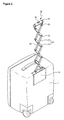
- FIG. 2 is a perspective view of a foldable cross-patterned pull-handle according to a first exemplary embodiment of the present invention, as well as a bag having the same.
- FIG. 3 is an exploded perspective view of the foldable pull-handle.
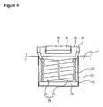
- FIG. 4 shows a folding means when folded and retracted.
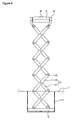
- FIG. 5 shows the folding means when unfolded.
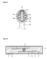
- FIG. 6 is a sectional view of fixing bars during sliding.
- FIG. 7 is a sectional view of a pinion gear when fixed.
- FIG. 8 is a sectional view of the pinion gear when unfixed.
- FIG. 9 is a sectional view of sliding plates of a support means during an operation.
- a foldable cross-patterned pull-handle As shown, a foldable cross-patterned pull-handle according to a first exemplary embodiment of the present invention, as well as a bag having the same, include a support means 10 mounted on the top of a lateral surface of the bag 1, a folding means 20 having one end fixed to the support means 10, a handle means 30 mounted on the other end of the folding means 20 and grabbed by the user with hand, and a fixing means 40 for temporarily fixing the folding means 20 when it has been extended to the length desired by the user.
- the folding means 20 has a number of link assemblies 24 connected to each other in the following manner.
- the first link assembly 24 has first and second links 21 and 22 and a rotation pin 23 rotatably coupling the center of the first link 21 to that of the second link 22 so that they cross each other.
- First ends of the first and second links 21 and 22 of the first link assembly 24 are rotatably coupled to second ends of the first and second links 21 and 22 of the second link assembly 24 by rotation pins 23, respectively.
- the support means 10 is either positioned inside the bag 1 or mounted on the outside.
- the support means 10 is preferably mounted in a detachable manner.
- various attaching/detaching methods can be employed, such as using bolts or fixing clamps.
- the support means 10 includes a case 11 provided with a receiving space 11a, which has an opening so that the folding means 20 can be received therein, and detachably mounted on the top of the outer peripheral surface of the bag 1, guide rails 12 mounted in the receiving space opposite the opening 11b of the case 11, and sliding plates 13 mounted so as to slide along rails 12a, which are formed on the guide rails 12, and provided with rack gear portions 13a consisting of a number of teeth arranged on a lateral surface in the longitudinal direction, respectively.
- first link 21 may have an end coupled to the sliding plates 13 so that it can rotate while sliding
- second link 22 may have an end hinge-coupled to the bottom of the case 11 so that the folding means 20 is supported while being able to fold/unfold.
- a pair of guide rails 12 is preferably mounted in parallel with each other as shown in the drawings.
- the support means 10 includes a fixing pinion gear 14 rotatably mounted between the sliding plates 13 to engage with respective rack gear portions 13a, and gap maintenance plates 15 fixed to the sliding plates 13.
- the gap maintenance plates 15 extend toward the position of the folding means 20, and the ends of the first and second links 21 and 22 are rotatably hinge-coupled to the gap maintenance plates 15, respectively.
- the handle means 30 includes a handle housing 31 grabbed by the user with hand, a sliding hole 31a extending through one side of the handle housing 31, and fixing bars 32 mounted on both ends of the sliding hole 31a while being able to slide.
- the other end of the folding means 20 is rotatably connected to the end of the fixing bars 32, which is exposed out of the handle housing 31. More specifically, the ends of the first and second links 21 and 22 are hinge-coupled to the fixing bars 32, respectively.
- tubular covers 33 are mounted between the handle housing 31 and the fixing bars 32, respectively. Each cover 33 has a groove 33a formed thereon to avoid interference with other components.
- the fixing means 40 is interposed between the middle portions of the fixing bars 32.
- first link 21 may have an end coupled to the fixing bar 32 so that it can rotate while sliding
- second link 22 may have an end hinge-coupled to the end of handle housing 31 so that the folding means 20 is supported while being able to fold/unfold.
- a pair of fixing bars 32 is preferably mounted as shown in the drawings.
- the fixing means 40 includes rack gears 41 having teeth formed in the longitudinal direction, one end of the rack gears 41 being fixed to the fixing bars 32; a pinion gear 42 mounted between the rack gears 41 to simultaneously mesh with the rack gears 41, the pinion gear 42 having at least one fixing groove 42a formed on a lateral surface; a pinion shaft 43 rotatably fixing the pinion gear 42, the pinion shaft 43 having a fixing protrusion 43a formed on one end and adapted to be temporarily inserted into the fixing groove 42a; an elastic member 44 elastically supporting one end of the pinion shaft 43; and a fixing button 45, to which the other end of the pinion shaft 43 is fixed, and the top of which is exposed to the outside via a button hole 31b formed on the handle housing 31.
- the pull-handle according to the first exemplary embodiment of the present invention which is constructed as described above, is operated in the following manner: as shown in FIGs. 4 and 5 , the link assemblies 24 constituting the folding means 20 are folded on each other or unfolded from each other so that the pull-handle is retracted into or extended from the receiving space 11a of the case 11.
- the handle means 30 and the fixing means 40 move in such a direction that the fixing bars 32 protrude out of the handle housing 32, as shown in FIGs. 6-8 .
- the handle means 30 and the fixing means 40 move in such a direction that the fixing bars 32 retract into the handle housing 31.
- the folding means 20 remains in the fixed condition. In other words, if the folding means 20 has been extended by a specific length, the folding means 20 maintains the length.
- the elastic member 44 When the user presses the fixing button 45, the elastic member 44 is deformed, and the pinion shaft 43 is moved, as shown in FIG. 8 . Then, the fixing protrusion 43a escapes from the fixing groove 42a so that the pinion gear 42 can rotate.
- the fact that the pinion gear 42 can rotate means that the fixing bars 32 connected to the rack gears 41 meshing with the pinion gear 42 can move and that the folding means 20 can be folded or unfolded. In other words, the folding means 20 switches from the fixed condition to a movable condition, in which its length can be varied. If the user stops pressing the fixing button 45, the elastic force from the elastic member 44 returns the pinion shaft 43 to the fixed condition as shown in FIG. 7 .
- the sliding plates 13 connected to the gap maintenance plates 15, to which the folding means 20 is hinge-coupled, interwork with each other while meshing with the fixing pinion gear 14. That is, the sliding plates 13 move while maintaining the same gap with regard to the center portion.
- the gap maintenance plates 15 prevent the folding means 20 from contacting the fixing pinion gear 14.
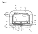
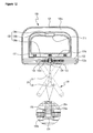
- a foldable cross-patterned pull-handle according to a second exemplary embodiment of the present invention, as well as a bag having the same, include a closed-shaped handle housing 131 having a handle portion 131a grabbed by the user with hand and a connection portion 131b, into which the other end of the folding means 20 is inserted; a pair of guide rails 132 mounted along both inner surfaces of the connection portion 131b in parallel with each other; fixing bars 133, to which ends of first and second links 21 and 22 constituting the folding means 20 are rotatably hinge-coupled, respectively, the fixing bars 133 being adapted to slide along rails 132a formed on the guide rails 132, respectively, and provided with rack gear portions 133a consisting of a number of teeth arranged on opposite surfaces in the longitudinal direction, respectively; a pinion gear 134 mounted between the rack gear portions 133a to simultaneously mesh with the rack gear portions 133a, the pinion gear 134 having at least one fixing groove 134a formed at
- the fixing member 136 includes a support portion 136a positioned adjacent to the connection portion 131b, the pinion shaft 135 being fixed to the support portion 136a, an extension portion 136b extending from the support portion 136a to the handle portion 131a, and a fixing button 136c formed on the extension portion 136b, the top of the fixing button 136c being exposed via a button hole 131c, which is formed inside the handle portion 131a of the handle housing 131.
- One side of the elastic member 137 makes contact with the support portion 136a, and the other side is supported on the inner surface of the handle housing 131. Particularly, the elastic member 137 supports a surface of the support portion 136a opposite the surface on which the pinion shaft 135 is mounted.
- the support means 10 and the folding means 20, on which the handle member 130 is mounted have the same construction and operation as in the first embodiment of the present invention described above.
- the foldable cross-patterned pull-handle having the above-mentioned construction is operated in the following manner: when the elastic member 137 compresses the fixing member 136 so that the fixing protrusion 135a formed on the pinion shaft 135 is inserted into the fixing groove 134a formed on the pinion gear 134, as shown in FIG. 11 , the fixed pinion shaft 135 causes the pinion gear 134 to stop rotating. Then, the fixing bars 133 having rack gear portions 133a formed thereon also remain still. As a result, the folding means 20 remains in the fixed condition. In other words, if the folding means 20 has been extended by a specific length, the folding means 20 maintains the length.
- the elastic member 137 When the user presses the fixing button 136c, as shown in FIG. 12 , the elastic member 137 is compressed, and the pinion shaft 135 is moved. Then, the fixing protrusion 135a escapes from the fixing groove 134a so that the pinion gear 134 can rotate.
- the fact that the pinion gear 134 can rotate means that the fixing bars 133 provided with the rack gear portions 133a meshing with the pinion gear 134 can move and that the folding means 20 can be folded or unfolded. In other words, the folding means 20 switches from the fixed condition to a movable condition, in which its length can be varied. If the user stops pressing the fixing button 136c, the elastic force from the elastic member 137 returns the pinion shaft 135 to the fixed condition as shown in FIG. 11 .
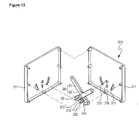
- a foldable cross-patterned pull-handle and a bag having the same according to a third exemplary embodiment of the present invention are constructed as shown in FIGs. 13 to 15 .
- a support means 210 can be inserted into a bag 1 or mounted on the outside. Preferably the support means 210 is mounted in a detachable manner. Although not shown in the drawings, various attachment/detachment methods can be employed such as fastening bolts or fixing clamps.
- the support means 210 includes a case 211 provided with a receiving space 211a with one open side so that the folding means 20 can be received therein, and detachably mounted on the outer peripheral surface of the bag 1; perpendicular links 212 formed at one end portion of the folding means 20, one end portions thereof being rotatably hinge-coupled respectively to one end portions of the first link 21 and the second link 22; a perpendicular pin 213 coupling and rotatably supporting the other end portions of the perpendicular links 212 each other; and sliding pins 214 mounted at one end portions of the first link 21 and the second link 22 formed at one end portion of the folding means 20.
- the case 211 has a fixing groove 215 formed on the lateral surface of the interior of the receiving space 211a, in which both ends of a rotation pin 23 mounted at the center portion of the first link 21 and the second link 22 are fixed; a perpendicular groove 216 recessed at the bottom portion of the fixing groove 215 at a predetermined depth and extending in parallel to the moving trajectory of the folding means 20 so that the perpendicular pin 213 can be slidably inserted therein; and a sliding groove 217 recessed in pairs left and right at a predetermined depth so that the sliding pin 214 can be slidably inserted therein, and extending so as to form an arc with the center at the fixing groove 215.
- the construction and operation of the folding means 20 and the handle means 30, 130, which are mounted on the support means 210, are the same as in the first and the second exemplary embodiments of the present invention.
- the support means 210 as above is constituted such that the perpendicular link 212 is rotated by a folding and extending operation of the folding means 20 so that the perpendicular link 212 slides along the perpendicular groove 216.
- the movement of the perpendicular link 212 is restricted by the perpendicular groove 216 so as to be parallel with the moving trajectory of the folding means 20 so that the perpendicular link 212 does not deviate from a moving path when the folding means 20 is folded and extended.
- the perpendicular pin 213 since the movement of the perpendicular pin 213 is restricted by the perpendicular groove 216, the perpendicular pin 213 is not rotated in the left or right direction based on the rotation pin 23 fixed on the case while the folding means 20 is extended.
- a foldable cross-patterned pull-handle according to a fourth exemplary embodiment of the present invention comprises a handle means 330.
- the handle means 330 comprises a handle housing 331 grabbed by the user with hand, a sliding hole 331a extending through one side of the handle housing 331; an internal housing 332 mounted on both ends of the sliding hole 331a so as to slide along the sliding hole; and fixing bars 333 connected to both ends of the outside of the internal housing 332, the other end of the folding means 20 is rotatably connected to the extended end of the fixing bars 333. More specifically, the ends of the first and second links 21 and 22 are hinge-coupled to the fixing bars 333, respectively.
- a fixing means 340 is interposed between the middle portions of the fixing bars 333.
- the fixing means 340 comprises ball housings 341 mounted on both ends of the internal housing 332; sliding balls 341a mounted on the ball housings 341 while being able to roll and protruding toward a center of the internal housing 332; screw shafts 342 mounted on both sides of the sliding hole 331a in the identical directions with each other based on the center of the sliding hole 331a and having screw grooves 342a formed on the outer peripheral surface and wound in the identical directions with each other based on the center of the sliding hole 331a; a bearing 343 rotatably supporting the screw shafts 342; a cover 344, into which the internal housing 332 is inserted, and which is rotatably mounted on the inside of the handle housing 331, and to which the bearing 343 is fixed; brakes 345 mounted on the ends of each screw shaft 342 to be able to temporarily contact each other and having a plurality of friction protrusions formed on each contact surface 345a where the brakes contact each other; springs 346 mounted between each brake 345 and each bearing 3
- a plurality of the sliding balls 341a are arranged at equal intervals with regard to the screw shaft 342, and the number of the screw grooves 342a formed on the screw shaft 342 is the same as that of the sliding balls 341a.
- the standoff pins 348 are preferably formed at intervals of 180 degrees so as to be symmetrical to each other, and the pressing protrusions 331b are also formed at two positions corresponding to those of the standoff pins 348.
- compression springs are preferably interposed between the standoff pins 348 and the pin housings 347 so as to elastically support the standoff pins 348.
- the foldable cross-patterned pull-handle according to a fourth exemplary embodiment of the present invention which is constructed as described above, is operated in the following manner: as shown in FIGs. 17 and 18 , when the folding means 20 is folded, the fixing bars 333 move in such a direction that the fixing bars 333 protrude out of the handle housing 331, and when the folding means 20 is unfolded and elongated, the fixing bars 333 move in such a direction that the fixing bars 333 retract into the handle housing 331.
- the fixing bars 333 formed on both sides of the handle housing 331 slide while maintaining the same gap with regard to the center of the handle housing 331, and the sliding balls 341a connected to the fixing bars 333 move in the left or right direction so that each screw shaft 342 having the screw grooves 342a can simultaneously rotate.
- the handle housing 331 When the folding means is to be unfolded, the handle housing 331 is rotated as shown in FIG. 17 . Then, the pressing protrusions 331b press the standoff pins 348, and the protruding portions of the standoff pins 348 are inserted between the brakes 345 so that the contact surfaces 345a are separated and each brake 345 can rotate.
- the screw shaft 342 can also rotate. Accordingly, since the sliding balls 341a inserted and fixed in the screw grooves 342a can roll and move along the screw grooves 342a rotating, the folding means 20 can be folded or unfolded. In other words, when the brakes 345 closely contacting each other are separated by the standoff pins 348 so that each brake 345 can rotate and be unfixed, the length of the folding means 20 can be adjusted.
- the handle housing 331 When the folding means 20 is to be fixed while unfolded by a specific length, as shown in FIG. 18 , the handle housing 331 is rotated in the opposite direction while the folding means 20 is unfolded by a specific length. Then, the pressing protrusions 331b pressing the standoff pins 348 are released, and the elastic force returns the standoff pins 348 to the original state so that the standoff pins escape from the brakes 345.
- the standoff pins 348 escape, the contact surfaces 345a of each brake 345 contact each other by the elastic force of the spring 346, and the friction protrusions mesh with each other to restrain the rotation so that each screw shaft 342 cannot separately rotate.
- both screw shafts 341 should rotate counterclockwise with regard to the contact surfaces 345a, and in order for the fixing bars 333 to retract to the inside, both screw shafts 341 should rotate clockwise with regard to the contact surfaces 345a. Accordingly, if the brakes 345 closely contact each other so that each brake cannot separately rotate, the rotational force of both screw shafts 342 is attenuated and the folding means 20 can remain unfolded by a specific length.
- the foldable cross-patterned pull-handle according to the present invention is advantageous in that the folding means, which is adapted to be folded/unfolded, is installed in a reduced installation space, compared with conventional pull-handles.
- the bag can contain more items. This improves the performance of the product.
- the user can use the fixing means, which is mounted on the handle means, to extend the folding means up to a desired length and temporarily fix it in any extended condition. This improves user convenience.
Landscapes
- Purses, Travelling Bags, Baskets, Or Suitcases (AREA)
Applications Claiming Priority (1)
| Application Number | Priority Date | Filing Date | Title |
|---|---|---|---|
| KR20080030244 | 2008-04-01 |
Publications (3)
| Publication Number | Publication Date |
|---|---|
| EP2106717A2 true EP2106717A2 (fr) | 2009-10-07 |
| EP2106717A3 EP2106717A3 (fr) | 2011-07-20 |
| EP2106717B1 EP2106717B1 (fr) | 2012-05-16 |
Family
ID=40957589
Family Applications (1)
| Application Number | Title | Priority Date | Filing Date |
|---|---|---|---|
| EP08252145A Not-in-force EP2106717B1 (fr) | 2008-04-01 | 2008-06-20 | Poignée dépliable en ciseaux et sac en disposant |
Country Status (4)
| Country | Link |
|---|---|
| US (1) | US7934289B2 (fr) |
| EP (1) | EP2106717B1 (fr) |
| JP (1) | JP4686576B2 (fr) |
| CN (1) | CN101548813B (fr) |
Cited By (2)
| Publication number | Priority date | Publication date | Assignee | Title |
|---|---|---|---|---|
| ITTV20090137A1 (it) * | 2009-06-26 | 2010-12-27 | Gianbattista Causin | Valigia tipo trolley |
| EP2930119A3 (fr) * | 2014-04-09 | 2016-01-06 | Ernst Kraemer & Söhne GmbH & Co. KG | Poignée de transport à disposer sur un emballage |
Families Citing this family (5)
| Publication number | Priority date | Publication date | Assignee | Title |
|---|---|---|---|---|
| KR100960077B1 (ko) * | 2010-03-16 | 2010-05-31 | 주식회사 캐리맥스통상 | 신축길이의 정밀도가 향상된 핸들부를 구비한 가방 |
| US10405644B2 (en) * | 2015-09-11 | 2019-09-10 | Nevaan Kothari | Hold a dental cleaning device on food related accessories |
| US20170086555A1 (en) * | 2015-09-28 | 2017-03-30 | Biogenesys, Inc. | Space-saving suitcase handle assemblies |
| CN111838918B (zh) * | 2020-08-26 | 2022-03-22 | 广东锦锐旅行用品有限公司 | 一种利用升降智能改变使用状态的行李箱 |
| CN113786130B (zh) * | 2021-09-27 | 2023-02-24 | 上海高仙自动化科技发展有限公司 | 一种把手模块及清洁机器人 |
Citations (1)
| Publication number | Priority date | Publication date | Assignee | Title |
|---|---|---|---|---|
| GB2111917A (en) | 1981-07-16 | 1983-07-13 | Angus Christopher Firth | Trolley |
Family Cites Families (12)
| Publication number | Priority date | Publication date | Assignee | Title |
|---|---|---|---|---|
| FR956119A (fr) * | 1950-01-26 | |||
| US1628563A (en) * | 1925-07-20 | 1927-05-10 | Taylor John | Battery-plate puller |
| US2653826A (en) * | 1951-03-20 | 1953-09-29 | Lu Yen-Shen | Portable foldable shopping basket |
| US3112135A (en) * | 1961-04-03 | 1963-11-26 | Salomonson Conrad | Handy extending grip |
| FR1401689A (fr) * | 1964-06-26 | 1965-06-04 | Petit diable pliant à plusieurs servitudes | |
| FR2272574A7 (en) * | 1974-05-20 | 1975-12-19 | Roussel Etienne | Collapsible suitcase trolley with lazy tongs handle - is locked in extended position by ring with handle folding over |
| DE2653316A1 (de) * | 1976-11-24 | 1978-06-01 | Franz Ritter | Spreiz- bzw. klemmgreifer |
| US4109952A (en) * | 1977-02-09 | 1978-08-29 | Michel Monzain | Package lifter |
| CN1201632A (zh) | 1997-10-27 | 1998-12-16 | 陈平和 | 旅行箱拉杆和定位机构及其制造方法 |
| KR100322564B1 (ko) | 1998-03-20 | 2002-07-02 | 윤종용 | 인쇄기의현상액공급장치 |
| CN1217614C (zh) * | 2001-02-22 | 2005-09-07 | 田村义昭 | 带折叠式推车的旅行包 |
| JP3793174B2 (ja) * | 2003-05-21 | 2006-07-05 | 株式会社スワニー | キャスター付きの鞄 |
-
2008
- 2008-06-19 US US12/142,513 patent/US7934289B2/en not_active Expired - Fee Related
- 2008-06-20 EP EP08252145A patent/EP2106717B1/fr not_active Not-in-force
- 2008-06-27 JP JP2008169223A patent/JP4686576B2/ja not_active Expired - Fee Related
- 2008-07-18 CN CN2008101265964A patent/CN101548813B/zh not_active Expired - Fee Related
Patent Citations (1)
| Publication number | Priority date | Publication date | Assignee | Title |
|---|---|---|---|---|
| GB2111917A (en) | 1981-07-16 | 1983-07-13 | Angus Christopher Firth | Trolley |
Cited By (2)
| Publication number | Priority date | Publication date | Assignee | Title |
|---|---|---|---|---|
| ITTV20090137A1 (it) * | 2009-06-26 | 2010-12-27 | Gianbattista Causin | Valigia tipo trolley |
| EP2930119A3 (fr) * | 2014-04-09 | 2016-01-06 | Ernst Kraemer & Söhne GmbH & Co. KG | Poignée de transport à disposer sur un emballage |
Also Published As
| Publication number | Publication date |
|---|---|
| US7934289B2 (en) | 2011-05-03 |
| JP4686576B2 (ja) | 2011-05-25 |
| JP2009247883A (ja) | 2009-10-29 |
| EP2106717B1 (fr) | 2012-05-16 |
| CN101548813A (zh) | 2009-10-07 |
| CN101548813B (zh) | 2012-08-29 |
| EP2106717A3 (fr) | 2011-07-20 |
| US20090242342A1 (en) | 2009-10-01 |
Similar Documents
| Publication | Publication Date | Title |
|---|---|---|
| EP2106717B1 (fr) | Poignée dépliable en ciseaux et sac en disposant | |
| KR101760075B1 (ko) | 수화물백용 래칫형 확장 시스템 | |
| CN211423148U (zh) | 一种滑动展开式柔性屏终端的铰链 | |
| US20100283227A1 (en) | Service cart | |
| JP4750794B2 (ja) | 拡張可能な旅行かばん | |
| CN110239608A (zh) | 婴幼儿推车 | |
| US20090139026A1 (en) | Foldable bed | |
| CA2765139A1 (fr) | Caisse pliable | |
| WO2011100235A1 (fr) | Verrou à tige à action commandée latéralement | |
| JP2019526499A5 (fr) | ||
| KR100950500B1 (ko) | 접이식 손잡이 및 이를 구비한 가방 | |
| CN102486203A (zh) | 铰链结构及应用该铰链结构的便携式电子装置 | |
| US6357566B1 (en) | Carry-on case | |
| US20030025361A1 (en) | Chair folding structure | |
| KR100537017B1 (ko) | 자동폐쇄장치가 부착된 슬라이드 | |
| TWI594638B (zh) | 耳機 | |
| KR20180110404A (ko) | 접이식 도어용 잠금장치 | |
| CN111147640B (zh) | 一种折叠铰链及移动内折终端 | |
| CN114542587A (zh) | 一种转轴装置 | |
| CN107804363A (zh) | 儿童推车安全锁及儿童推车 | |
| CN104100150A (zh) | 一种箱体结构及其按纽式弹销锁扣 | |
| KR101273132B1 (ko) | 노브 잠금장치 | |
| CN103567541A (zh) | 一种多形态折叠锯 | |
| KR100785468B1 (ko) | 루프캐리어의 루프랙과 크로스바의 록킹장치 | |
| CN217185094U (zh) | 一种拥有扩展空间功能的箱包 |
Legal Events
| Date | Code | Title | Description |
|---|---|---|---|
| PUAI | Public reference made under article 153(3) epc to a published international application that has entered the european phase |
Free format text: ORIGINAL CODE: 0009012 |
|
| AK | Designated contracting states |
Kind code of ref document: A2 Designated state(s): AT BE BG CH CY CZ DE DK EE ES FI FR GB GR HR HU IE IS IT LI LT LU LV MC MT NL NO PL PT RO SE SI SK TR |
|
| AX | Request for extension of the european patent |
Extension state: AL BA MK RS |
|
| PUAL | Search report despatched |
Free format text: ORIGINAL CODE: 0009013 |
|
| AK | Designated contracting states |
Kind code of ref document: A3 Designated state(s): AT BE BG CH CY CZ DE DK EE ES FI FR GB GR HR HU IE IS IT LI LT LU LV MC MT NL NO PL PT RO SE SI SK TR |
|
| AX | Request for extension of the european patent |
Extension state: AL BA MK RS |
|
| 17P | Request for examination filed |
Effective date: 20110906 |
|
| GRAP | Despatch of communication of intention to grant a patent |
Free format text: ORIGINAL CODE: EPIDOSNIGR1 |
|
| RIC1 | Information provided on ipc code assigned before grant |
Ipc: A45C 13/26 20060101AFI20111031BHEP Ipc: A45C 5/14 20060101ALN20111031BHEP |
|
| RIC1 | Information provided on ipc code assigned before grant |
Ipc: A45C 5/14 20060101ALN20111114BHEP Ipc: A45C 13/26 20060101AFI20111114BHEP |
|
| AKX | Designation fees paid |
Designated state(s): AT BE BG CH CY CZ DE DK EE ES FI FR GB GR HR HU IE IS IT LI LT LU LV MC MT NL NO PL PT RO SE SI SK TR |
|
| GRAS | Grant fee paid |
Free format text: ORIGINAL CODE: EPIDOSNIGR3 |
|
| GRAA | (expected) grant |
Free format text: ORIGINAL CODE: 0009210 |
|
| AK | Designated contracting states |
Kind code of ref document: B1 Designated state(s): AT BE BG CH CY CZ DE DK EE ES FI FR GB GR HR HU IE IS IT LI LT LU LV MC MT NL NO PL PT RO SE SI SK TR |
|
| REG | Reference to a national code |
Ref country code: GB Ref legal event code: FG4D |
|
| REG | Reference to a national code |
Ref country code: CH Ref legal event code: EP |
|
| REG | Reference to a national code |
Ref country code: AT Ref legal event code: REF Ref document number: 557607 Country of ref document: AT Kind code of ref document: T Effective date: 20120615 |
|
| REG | Reference to a national code |
Ref country code: IE Ref legal event code: FG4D |
|
| REG | Reference to a national code |
Ref country code: DE Ref legal event code: R096 Ref document number: 602008015581 Country of ref document: DE Effective date: 20120719 |
|
| PGFP | Annual fee paid to national office [announced via postgrant information from national office to epo] |
Ref country code: DE Payment date: 20120622 Year of fee payment: 5 |
|
| PGFP | Annual fee paid to national office [announced via postgrant information from national office to epo] |
Ref country code: GB Payment date: 20120622 Year of fee payment: 5 Ref country code: FR Payment date: 20120705 Year of fee payment: 5 |
|
| REG | Reference to a national code |
Ref country code: NL Ref legal event code: VDEP Effective date: 20120516 |
|
| REG | Reference to a national code |
Ref country code: LT Ref legal event code: MG4D Effective date: 20120516 |
|
| PG25 | Lapsed in a contracting state [announced via postgrant information from national office to epo] |
Ref country code: FI Free format text: LAPSE BECAUSE OF FAILURE TO SUBMIT A TRANSLATION OF THE DESCRIPTION OR TO PAY THE FEE WITHIN THE PRESCRIBED TIME-LIMIT Effective date: 20120516 Ref country code: LT Free format text: LAPSE BECAUSE OF FAILURE TO SUBMIT A TRANSLATION OF THE DESCRIPTION OR TO PAY THE FEE WITHIN THE PRESCRIBED TIME-LIMIT Effective date: 20120516 Ref country code: CY Free format text: LAPSE BECAUSE OF FAILURE TO SUBMIT A TRANSLATION OF THE DESCRIPTION OR TO PAY THE FEE WITHIN THE PRESCRIBED TIME-LIMIT Effective date: 20120516 Ref country code: PL Free format text: LAPSE BECAUSE OF FAILURE TO SUBMIT A TRANSLATION OF THE DESCRIPTION OR TO PAY THE FEE WITHIN THE PRESCRIBED TIME-LIMIT Effective date: 20120516 Ref country code: SE Free format text: LAPSE BECAUSE OF FAILURE TO SUBMIT A TRANSLATION OF THE DESCRIPTION OR TO PAY THE FEE WITHIN THE PRESCRIBED TIME-LIMIT Effective date: 20120516 Ref country code: NO Free format text: LAPSE BECAUSE OF FAILURE TO SUBMIT A TRANSLATION OF THE DESCRIPTION OR TO PAY THE FEE WITHIN THE PRESCRIBED TIME-LIMIT Effective date: 20120816 Ref country code: IS Free format text: LAPSE BECAUSE OF FAILURE TO SUBMIT A TRANSLATION OF THE DESCRIPTION OR TO PAY THE FEE WITHIN THE PRESCRIBED TIME-LIMIT Effective date: 20120916 |
|
| REG | Reference to a national code |
Ref country code: AT Ref legal event code: MK05 Ref document number: 557607 Country of ref document: AT Kind code of ref document: T Effective date: 20120516 |
|
| PG25 | Lapsed in a contracting state [announced via postgrant information from national office to epo] |
Ref country code: LV Free format text: LAPSE BECAUSE OF FAILURE TO SUBMIT A TRANSLATION OF THE DESCRIPTION OR TO PAY THE FEE WITHIN THE PRESCRIBED TIME-LIMIT Effective date: 20120516 Ref country code: GR Free format text: LAPSE BECAUSE OF FAILURE TO SUBMIT A TRANSLATION OF THE DESCRIPTION OR TO PAY THE FEE WITHIN THE PRESCRIBED TIME-LIMIT Effective date: 20120817 Ref country code: PT Free format text: LAPSE BECAUSE OF FAILURE TO SUBMIT A TRANSLATION OF THE DESCRIPTION OR TO PAY THE FEE WITHIN THE PRESCRIBED TIME-LIMIT Effective date: 20120917 Ref country code: HR Free format text: LAPSE BECAUSE OF FAILURE TO SUBMIT A TRANSLATION OF THE DESCRIPTION OR TO PAY THE FEE WITHIN THE PRESCRIBED TIME-LIMIT Effective date: 20120516 Ref country code: SI Free format text: LAPSE BECAUSE OF FAILURE TO SUBMIT A TRANSLATION OF THE DESCRIPTION OR TO PAY THE FEE WITHIN THE PRESCRIBED TIME-LIMIT Effective date: 20120516 |
|
| PG25 | Lapsed in a contracting state [announced via postgrant information from national office to epo] |
Ref country code: BE Free format text: LAPSE BECAUSE OF FAILURE TO SUBMIT A TRANSLATION OF THE DESCRIPTION OR TO PAY THE FEE WITHIN THE PRESCRIBED TIME-LIMIT Effective date: 20120516 |
|
| PG25 | Lapsed in a contracting state [announced via postgrant information from national office to epo] |
Ref country code: AT Free format text: LAPSE BECAUSE OF FAILURE TO SUBMIT A TRANSLATION OF THE DESCRIPTION OR TO PAY THE FEE WITHIN THE PRESCRIBED TIME-LIMIT Effective date: 20120516 Ref country code: DK Free format text: LAPSE BECAUSE OF FAILURE TO SUBMIT A TRANSLATION OF THE DESCRIPTION OR TO PAY THE FEE WITHIN THE PRESCRIBED TIME-LIMIT Effective date: 20120516 Ref country code: NL Free format text: LAPSE BECAUSE OF FAILURE TO SUBMIT A TRANSLATION OF THE DESCRIPTION OR TO PAY THE FEE WITHIN THE PRESCRIBED TIME-LIMIT Effective date: 20120516 Ref country code: CZ Free format text: LAPSE BECAUSE OF FAILURE TO SUBMIT A TRANSLATION OF THE DESCRIPTION OR TO PAY THE FEE WITHIN THE PRESCRIBED TIME-LIMIT Effective date: 20120516 Ref country code: SK Free format text: LAPSE BECAUSE OF FAILURE TO SUBMIT A TRANSLATION OF THE DESCRIPTION OR TO PAY THE FEE WITHIN THE PRESCRIBED TIME-LIMIT Effective date: 20120516 Ref country code: MC Free format text: LAPSE BECAUSE OF NON-PAYMENT OF DUE FEES Effective date: 20120630 Ref country code: RO Free format text: LAPSE BECAUSE OF FAILURE TO SUBMIT A TRANSLATION OF THE DESCRIPTION OR TO PAY THE FEE WITHIN THE PRESCRIBED TIME-LIMIT Effective date: 20120516 Ref country code: EE Free format text: LAPSE BECAUSE OF FAILURE TO SUBMIT A TRANSLATION OF THE DESCRIPTION OR TO PAY THE FEE WITHIN THE PRESCRIBED TIME-LIMIT Effective date: 20120516 |
|
| REG | Reference to a national code |
Ref country code: CH Ref legal event code: PL |
|
| REG | Reference to a national code |
Ref country code: CH Ref legal event code: PL |
|
| PG25 | Lapsed in a contracting state [announced via postgrant information from national office to epo] |
Ref country code: IT Free format text: LAPSE BECAUSE OF FAILURE TO SUBMIT A TRANSLATION OF THE DESCRIPTION OR TO PAY THE FEE WITHIN THE PRESCRIBED TIME-LIMIT Effective date: 20120516 |
|
| PLBE | No opposition filed within time limit |
Free format text: ORIGINAL CODE: 0009261 |
|
| STAA | Information on the status of an ep patent application or granted ep patent |
Free format text: STATUS: NO OPPOSITION FILED WITHIN TIME LIMIT |
|
| REG | Reference to a national code |
Ref country code: IE Ref legal event code: MM4A |
|
| 26N | No opposition filed |
Effective date: 20130219 |
|
| PG25 | Lapsed in a contracting state [announced via postgrant information from national office to epo] |
Ref country code: IE Free format text: LAPSE BECAUSE OF NON-PAYMENT OF DUE FEES Effective date: 20120620 Ref country code: ES Free format text: LAPSE BECAUSE OF FAILURE TO SUBMIT A TRANSLATION OF THE DESCRIPTION OR TO PAY THE FEE WITHIN THE PRESCRIBED TIME-LIMIT Effective date: 20120827 Ref country code: LI Free format text: LAPSE BECAUSE OF NON-PAYMENT OF DUE FEES Effective date: 20120630 Ref country code: CH Free format text: LAPSE BECAUSE OF NON-PAYMENT OF DUE FEES Effective date: 20120630 |
|
| REG | Reference to a national code |
Ref country code: DE Ref legal event code: R097 Ref document number: 602008015581 Country of ref document: DE Effective date: 20130219 |
|
| PG25 | Lapsed in a contracting state [announced via postgrant information from national office to epo] |
Ref country code: BG Free format text: LAPSE BECAUSE OF FAILURE TO SUBMIT A TRANSLATION OF THE DESCRIPTION OR TO PAY THE FEE WITHIN THE PRESCRIBED TIME-LIMIT Effective date: 20120816 Ref country code: MT Free format text: LAPSE BECAUSE OF FAILURE TO SUBMIT A TRANSLATION OF THE DESCRIPTION OR TO PAY THE FEE WITHIN THE PRESCRIBED TIME-LIMIT Effective date: 20120516 |
|
| GBPC | Gb: european patent ceased through non-payment of renewal fee |
Effective date: 20130620 |
|
| REG | Reference to a national code |
Ref country code: FR Ref legal event code: ST Effective date: 20140228 |
|
| REG | Reference to a national code |
Ref country code: DE Ref legal event code: R119 Ref document number: 602008015581 Country of ref document: DE Effective date: 20140101 |
|
| PG25 | Lapsed in a contracting state [announced via postgrant information from national office to epo] |
Ref country code: TR Free format text: LAPSE BECAUSE OF FAILURE TO SUBMIT A TRANSLATION OF THE DESCRIPTION OR TO PAY THE FEE WITHIN THE PRESCRIBED TIME-LIMIT Effective date: 20120516 Ref country code: DE Free format text: LAPSE BECAUSE OF NON-PAYMENT OF DUE FEES Effective date: 20140101 Ref country code: GB Free format text: LAPSE BECAUSE OF NON-PAYMENT OF DUE FEES Effective date: 20130620 |
|
| PG25 | Lapsed in a contracting state [announced via postgrant information from national office to epo] |
Ref country code: LU Free format text: LAPSE BECAUSE OF NON-PAYMENT OF DUE FEES Effective date: 20120620 Ref country code: FR Free format text: LAPSE BECAUSE OF NON-PAYMENT OF DUE FEES Effective date: 20130701 |
|
| PG25 | Lapsed in a contracting state [announced via postgrant information from national office to epo] |
Ref country code: HU Free format text: LAPSE BECAUSE OF FAILURE TO SUBMIT A TRANSLATION OF THE DESCRIPTION OR TO PAY THE FEE WITHIN THE PRESCRIBED TIME-LIMIT Effective date: 20080620 |