EP2106761B1 - Implantat zum Beabstanden von benachbarten Knochen einer Wirbelsäule - Google Patents
Implantat zum Beabstanden von benachbarten Knochen einer Wirbelsäule Download PDFInfo
- Publication number
- EP2106761B1 EP2106761B1 EP08019603A EP08019603A EP2106761B1 EP 2106761 B1 EP2106761 B1 EP 2106761B1 EP 08019603 A EP08019603 A EP 08019603A EP 08019603 A EP08019603 A EP 08019603A EP 2106761 B1 EP2106761 B1 EP 2106761B1
- Authority
- EP
- European Patent Office
- Prior art keywords
- implant
- implant body
- pin
- cylindrical
- spinous processes
- Prior art date
- Legal status (The legal status is an assumption and is not a legal conclusion. Google has not performed a legal analysis and makes no representation as to the accuracy of the status listed.)
- Not-in-force
Links
- 239000007943 implant Substances 0.000 title claims abstract description 104
- 210000000988 bone and bone Anatomy 0.000 title claims description 7
- 238000000034 method Methods 0.000 claims abstract description 37
- 238000013016 damping Methods 0.000 claims abstract description 11
- RTAQQCXQSZGOHL-UHFFFAOYSA-N Titanium Chemical compound [Ti] RTAQQCXQSZGOHL-UHFFFAOYSA-N 0.000 claims description 15
- 229910052719 titanium Inorganic materials 0.000 claims description 15
- 239000010936 titanium Substances 0.000 claims description 15
- 238000002513 implantation Methods 0.000 claims description 10
- 238000004904 shortening Methods 0.000 claims description 5
- 238000010297 mechanical methods and process Methods 0.000 claims description 2
- 230000005226 mechanical processes and functions Effects 0.000 claims 1
- 230000003068 static effect Effects 0.000 claims 1
- 241000207965 Acanthaceae Species 0.000 abstract 3
- 230000008719 thickening Effects 0.000 description 3
- 208000002193 Pain Diseases 0.000 description 2
- 238000001514 detection method Methods 0.000 description 2
- 230000005021 gait Effects 0.000 description 2
- 239000000463 material Substances 0.000 description 2
- 239000004033 plastic Substances 0.000 description 2
- 229920003023 plastic Polymers 0.000 description 2
- 230000006641 stabilisation Effects 0.000 description 2
- 238000011105 stabilization Methods 0.000 description 2
- 241000272525 Anas platyrhynchos Species 0.000 description 1
- 208000008035 Back Pain Diseases 0.000 description 1
- 206010023509 Kyphosis Diseases 0.000 description 1
- 208000007623 Lordosis Diseases 0.000 description 1
- 239000000956 alloy Substances 0.000 description 1
- 229910045601 alloy Inorganic materials 0.000 description 1
- 239000013013 elastic material Substances 0.000 description 1
- 210000003041 ligament Anatomy 0.000 description 1
- 239000007769 metal material Substances 0.000 description 1
- 210000003205 muscle Anatomy 0.000 description 1
- HLXZNVUGXRDIFK-UHFFFAOYSA-N nickel titanium Chemical compound [Ti].[Ti].[Ti].[Ti].[Ti].[Ti].[Ti].[Ti].[Ti].[Ti].[Ti].[Ni].[Ni].[Ni].[Ni].[Ni].[Ni].[Ni].[Ni].[Ni].[Ni].[Ni].[Ni].[Ni].[Ni] HLXZNVUGXRDIFK-UHFFFAOYSA-N 0.000 description 1
- 229910001000 nickel titanium Inorganic materials 0.000 description 1
- 230000000399 orthopedic effect Effects 0.000 description 1
- 238000002360 preparation method Methods 0.000 description 1
- 210000000954 sacrococcygeal region Anatomy 0.000 description 1
- 238000000926 separation method Methods 0.000 description 1
- 238000001356 surgical procedure Methods 0.000 description 1
- 229920001169 thermoplastic Polymers 0.000 description 1
- 239000004416 thermosoftening plastic Substances 0.000 description 1
- 210000000115 thoracic cavity Anatomy 0.000 description 1
- 210000001364 upper extremity Anatomy 0.000 description 1
Images

Classifications
-
- A—HUMAN NECESSITIES
- A61—MEDICAL OR VETERINARY SCIENCE; HYGIENE
- A61B—DIAGNOSIS; SURGERY; IDENTIFICATION
- A61B17/00—Surgical instruments, devices or methods
- A61B17/56—Surgical instruments or methods for treatment of bones or joints; Devices specially adapted therefor
- A61B17/58—Surgical instruments or methods for treatment of bones or joints; Devices specially adapted therefor for osteosynthesis, e.g. bone plates, screws or setting implements
- A61B17/68—Internal fixation devices, including fasteners and spinal fixators, even if a part thereof projects from the skin
- A61B17/70—Spinal positioners or stabilisers, e.g. stabilisers comprising fluid filler in an implant
- A61B17/7062—Devices acting on, attached to, or simulating the effect of, vertebral processes, vertebral facets or ribs ; Tools for such devices
Definitions
- the invention relates to an implant according to the preamble of patent claim 1.
- the spine of an adult is usually doubly s-shaped curved so that it helps quasi as a resilient rod especially the upright people to an elastic gait, known to be forward convex curvature in the cervical and lumbar vertebrae as lordosis and the back convex curvature in the thoracic and sacral region is called kyphosis.
- kyphosis the back convex curvature in the thoracic and sacral region.
- the distance of adjacent spinous processes to the disadvantage of the patient may be markedly reduced due to illness, which can cause considerable pain, when the patient is moving, ie when relative movements occur between such bone portions of the spine.
- the US 2005/0203512 A1 an implant for spacing vertebral bodies.
- This has a side part, a middle part and a deformation section.
- the deformation section is designed to implant the implant so that it represents an extension of the central section and can be inserted through the vertebral bodies.
- the deformation portion may be deformed to another side portion that holds the implant between the vertebral bodies.
- a comparable implant reveals the US 6,235,030 B1 , Here, the holding plates are inserted at a central part, which is already introduced between the vertebral bodies and the spinous processes.
- the disclosed WO 2006/113080 A2 an implant that can be deformed according to the principle of a blind rivet.
- the deformation sections have predetermined breaking points at which the deformation sections bend and thus form retaining flanges.
- US 2006/0184247 A1 discloses an implant for spacing vertebral bones. This has deformation sections. The deformation portions can be compressed from the outside so that they form retaining flanges.
- the US 2006/0084988 A1 discloses an implant that can be deformed on the principle of a blind rivet. At the same time, the entire implant body, including the middle area that lies between the bones, expands.
- the invention has for its object to provide an implant for spacing of adjacent bones of a spine, in particular of the vertebral arches
- backward spinous processes which is minimally invasive implantable while allowing the degrees of freedom of the spine, such as forward and backward movement, side tilt and rotation.
- a relatively slender cylindrical implant body as the starting shape is implanted between the spinous processes to be spaced and then fixed in the manner of a rivet on the spinous processes.
- a cylindrical implant body with a middle damping section adjoining both sides of a deformation section is used for the initial shape of the implant, wherein the deformation sections after implantation for fixing the implant to adjacent spinous processes are each deformed to retaining flanges, which only rest against the spinous processes and are not screwed with these.
- the cylindrical implant body which is preferably circular in cross-section, for example, is produced with a longitudinal axis and is manufactured in whose central region is a tube, preferably made of titanium, is used, whose length corresponds to the maximum outer distance between the deformed retaining flanges in the implanted final state.
- the titanium tube also acts as an indicator for the detection of the implant on X-ray images.
- a pin preferably also made of titanium, is plugged, the longitudinal extent on one end side of the rod-shaped implant body with this practically completes and on the other end side of the hollow longitudinal axis protrudes.
- the blind-rivet principle can be achieved in a further development of the present invention, characterized in that the pin is provided on the final end side of the rod-shaped implant body with an attacking on the end face counter-disk, whereas on the protruding from the longitudinal axis of the implant body Trumm of the pin For the time being, a thrust washer which acts on this end side on the end face of the implant body is loosely pushed on.
- the introduction of the cylindrical implant body into the region to be spaced of the spinal column of a patient is carried out with the aid of a tubular implantation instrument which has in its front region the cylindrical implant body and a punch with which the implant body can be removed from the tubular instrument a desired position in the spine is brought, wherein the cylindrical implant body in this case in the Intermediate space of two spinous processes of a spinal column to be spaced apart is introduced so that the middle damping section of the implant body is located in the intermediate space and completely fills it, whereas the deformation sections extend on both sides of the spinous processes.
- This separation of the pin can also be facilitated by the free run of the pin for fixing the width of an inserted implant is provided with a predetermined breaking point at the after the deformation of the deformation sections of the implant body, the run of the pen is cut.
- Particularly suitable as the implant itself is a starting shape designed as a cylindrical implant body, which is designed with a central damping section and on either side thereof, each having a deformation section, wherein the deformation sections are designed to be plastically flexible in such a way that, after implantation of the starting body between adjacent spinous processes Fixing the damping portion of these in each case to the retaining flanges are deformable, ie the retaining flanges are elastic to the spinous processes without having to be screwed with them.
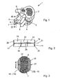
- the in Fig. 1 in oblique top view shown portion of a spinal column 1 has two adjacent vertebral bodies 2 and 3, between which a disc 4 is located. At the vertebral arches of the two vertebral bodies 2 and 3 extend backward next to transverse processes 5 and 6 (only given the vertebral body 1) in each case a spinous process 7 and 8, the gap 9 by an implant 10 (FIG. Fig. 3 ) is to be spaced in a first embodiment or according to Fig. 3 is.
- Fig. 2 is the initial shape of the implant 10 according to Fig. 3 as a cylindrical implant body 11 is shown schematically enlarged, of a medium damping portion 12 made of a permanently elastic plastic material such as a thermoplastic or a combination of materials of plastics and metallic materials or alloys such as titanium, nitinol, etc. and both sides deformation portions 13 and 14 of a plastically deformable, flexible or permanently elastic material possesses - as in Fig. 3 shown - have been deformed to retaining flanges 15 and 16.
- a medium damping portion 12 made of a permanently elastic plastic material such as a thermoplastic or a combination of materials of plastics and metallic materials or alloys such as titanium, nitinol, etc.
- deformation portions 13 and 14 of a plastically deformable, flexible or permanently elastic material possesses - as in Fig. 3 shown - have been deformed to retaining flanges 15 and 16.
- the cylindrical implant body 11 is circular in cross section and has a hollow longitudinal axis 17, in the central region of a tube 18 is inserted, which consists in the present embodiment of titanium, so that this one hand, as an indicator of detection
- the length of the tube 18 corresponds to the maximum outer distance between the deformed retaining flanges 15 and 16 in the implanted end state of the implant 10 (FIG. Fig. 3 ).
- titanium pin 19 terminates on the left end side with a counter-disc 20, whereas this protrudes on the right end side of the longitudinal axis 17 with a Trumm 21, on which a thrust washer 22 is threaded.
- a tubular implantation instrument 23 For introducing the cylindrical implant body 11 into the region of the vertebral body portion 1 to be separated, here the distance 9 in FIG Fig. 1 and in Fig. 3 , serves a tubular implantation instrument 23, which in Fig. 4 is shown schematically.
- the cylindrical implant body 11 or the in Fig. 6 shown cylindrical implant body 24 positioned as a second output form. Behind it is a punch 23 ', with which the initial shapes of the implants from the tubular instrument 23 can be brought into the desired position in the spinal column section 1.
- an implant fixation pliers for fixation of the implant 10 to the spinous processes 7 and 8 is an implant fixation pliers, not shown, which separately or in combination with the Impant istsinstrument 23 - as in Figure 4 indicated by dashed lines - can be used.
- the free Trumm 21 is according to Fig. 2 detected and shortened the length of the titanium pin 19 by squeezing the pliers handles so that a sufficient force on the counter and Duck disc 20th and 22 is produced in the end regions of the non-deformable deformation sections 13 and 14 in order then to deform them to the plastically or elastically deformed retaining flanges 15 and 16.
- the shortening distance of the free strand 21 of the titanium pin 19 can be limited by a predetermined breaking point 25 at this.
- the central titanium pin can be shortened to an arbitrary length and locked in its shortening position by mechanical deformation. Subsequently, the protruding piece of free Trumms be separated mechanically and spanok.
- a cylindrical implant body 11 In addition to the first embodiment of a cylindrical implant body 11 according to Fig. 2 Other embodiments are possible. So is in Fig. 5 as a second embodiment of the already mentioned implant body 24 shown schematically, one of whose deformation portion 26 tapers in the direction of its free end, that is formed as a section of an ellipsoid, in which case the diameter of the 27 designated counter-disc in the region of the ellipsoidal taper is designed to be correspondingly smaller the diameter of the associated with 28 designated thrust washer.
- FIG. 6 schematically an initial shape for an implant body 24 'and in Fig. 7 a molded therefrom implant 10 'shown as a third embodiment in which the counter and pressure plates designated 29 and 30 are arranged within the designated with 31 and 32 deformation sections, which then lead to retaining flanges 33 and 34 in the implanted final state.
- the method for introducing one of the implants according to the invention into the spinal column of a patient is carried out according to the following method of operation:
- an access to the affected portion of the spine by a small incision and possibly by a necessary free preparation is created laterally of the spine on the back of the patient.
- the implanting instrument 23 is connected to e.g. the cylindrical implant body 11 is attached by means of its sharp tip to the back opening, wherein by at least one lateral thickening or eccentric arrangement of the cylindrical, in particular tubular shape spreading of the spaced apart spinous processes is possible.
- the spreading can also be done by an oval thickening and a corresponding twisting or by an increasing diameter diameter thickening of the end portion of the tubular implantation instrument 23.
- the punch 23 ' which is designed so that it does not obstruct the titanium pin 19 of the cylindrical implant body 11.
- the implant body 11 is pushed out of the tubular end portion of the instrument 23 by the punch 23 'while at the same time the entire instrument 23 is withdrawn.
- the titanium pin is caught on the runner 21 and pulled in, so that pressure is applied to both discs 20 and 22 is exercised and thereby at the same time shorten the distance between the outer contours of the deformation sections 13 and 14, this deform to the retaining flanges 15 and 16.
- the titanium pin 19 is deformed or fixed at 21 'such that its set position remains fixed.
- the inserted implant 10 is dimensionally stable and precisely positioned by the tension and the restoring forces of the flexible outer regions, so that the patient again receives his three degrees of freedom with respect to his back movement, ie can move as usual without pain.
Landscapes
- Health & Medical Sciences (AREA)
- Orthopedic Medicine & Surgery (AREA)
- Life Sciences & Earth Sciences (AREA)
- Neurology (AREA)
- Surgery (AREA)
- Heart & Thoracic Surgery (AREA)
- Engineering & Computer Science (AREA)
- Biomedical Technology (AREA)
- Nuclear Medicine, Radiotherapy & Molecular Imaging (AREA)
- Medical Informatics (AREA)
- Molecular Biology (AREA)
- Animal Behavior & Ethology (AREA)
- General Health & Medical Sciences (AREA)
- Public Health (AREA)
- Veterinary Medicine (AREA)
- Prostheses (AREA)
- Surgical Instruments (AREA)
Description
- Die Erfindung betrifft ein Implantat gemäß dem Oberbegriff des Patentanspruchs 1.
- Die Wirbelsäule eines Erwachsenen ist in der Regel doppelt s-förmig gekrümmt, sodass sie quasi als federnder Stab vor allem dem aufrecht gehenden Menschen zu einem elastischen Gangbild verhilft, wobei bekanntlich die nach vorne konvexe Krümmung im Hals- und Lendenwirbelbereich als Lordose und die nach hinten konvexe Krümmung im Brust- und Sakralbereich als Kyphose bezeichnet wird. Nachdem die Wirbelsäule als Achse des Menschen den Kopf, die Rippen und die oberen Extremitäten tragen muss, ist sie des öfteren die Ursache von Rückenschmerzen, da deren einzelne Knochenabschnitte je nach Belastung und Verschleiß aneinander reiben können, sodass dadurch das elastische Gangbild nicht mehr aufrechterhalten werden kann.
- Insbesondere bei den so genannten Dornfortsätzen der Wirbelsäule, die ausgehend von den Wirbelbögen der einzelnen Wirbelkörper rückenwärts gerichtet sind und als Ansatzstellen für Bänder und Muskeln dienen, kann sich krankheitsbedingt jeweils der Abstand benachbarter Dornfortsätze zum Nachteil des Patienten merklich verringern, wodurch erhebliche Schmerzen auftreten können, wenn sich der Patient bewegt, d.h. wenn relative Bewegungen zwischen derartigen Knochenabschnitten der Wirbelsäule auftreten.
- Es gibt bereits in der orthopädischen Chirurgie eine Reihe von Verfahren zur Linderung von derartigen Rückenproblemen, die sich vor allem mit einem Stabilisieren der betroffenen Wirbel befassen, was z. B. durch ein mechanisches Verbinden der Wirbel miteinander gelöst werden kann. Ferner sind Verfahren bekannt, bei denen die rückenwärts gerichteten Dornfortsätze einer Wirbelsäule mit Hilfe eines Implantats beabstandet werden, damit diese sich nicht mehr berühren bzw. aneinander reiben können. So ist beispielsweise in der
US 2004/0193159 A1 ein derartiges Verfahren beschrieben, bei dem die Stabilisierung eines Abstands zwischen den Dornfortsätzen benachbarter Wirbelkörper mit Hilfe eines quasi zusammen- schraubbaren Implantats erreicht werden soll, das relativ aufwendig jeweils zwischen zwei benachbarten Dornfortsätzen chirurgisch eingesetzt wird. Dazu kommt, dass bei allen bekannten derartigen Verfahren mit eingesetzten Implantaten die hinterher erzielten Bewegungsmöglichkeiten des jeweiligen Patienten mehr oder weniger begrenzt bleiben. - Beispielsweise offenbart die
US 2005/0203512 A1 ein Implantat zum Beabstanden von Wirbelkörpern. Dieses weist ein Seitenteil, einen Mittelteil und einen Verformungsabschnitt auf. Der Verformungsabschnitt ist zur Implantierung des Implantates so ausgebildet, dass er eine Verlängerung des Mittelabschnitts darstellt und durch die Wirbelkörper hindurch gesteckt werden kann. Wenn das Implantat positioniert ist, kann der Verformungsabschnitt zu einem weiteren Seitenteil verformt werden, das das Implantat zwischen den Wirbelkörpern hält. - Ein vergleichbares Implantat offenbart die
US 6,235,030 B1 . Hier werden die Halteplatten an ein Mittelteil gesteckt, das bereits zwischen die Wirbelkörper bzw. die Dornfortsätze eingebracht ist. - Desweiteren offenbart die
WO 2006/113080 A2 ein Implantat, das nach dem Prinzip einer Blind-Niete verformbar ist. Die Verformungsabschnitte weisen Sollbruchstellen auf, an denen die Verformungsabschnitte abknicken und so Halteflansche ausbilden. - Auch die
US 2006/0184247 A1 offenbart ein Implantat zum Beabstanden von Wirbelknochen. Dieses weist Verformungsabschnitte auf. Die Verformungsabschnitte können von aussen so zusammengedrückt werden, dass sie Halteflansche ausbilden. - Auch die
US 2006/0084988 A1 offenbart ein Implantat, das nach dem Prinzip einer Blind-Niete verformt werden kann. Dabei weitet sich der ganze Implantatkörper, auch der mittlere Bereich, der zwischen den Knochen liegt, auf. Demgegenüber liegt der Erfindung die Aufgabe zugrunde, ein Implantat anzugeben zum Beabstanden von benachbarten Knochen einer Wirbelsäule, insbesondere von den Wirbelbögen der Wirbelkörper ausgehenden, rückenwärts gerichteten Dornfortsätze zu schaffen, das minimalinvasiv implantierbar ist und gleichzeitig die Freiheitsgrade der Wirbelsäule, wie Vor- und Rückbewegung, Seitenneigung und Drehung ermöglicht. - Die Aufgabe wird durch die Merkmale der kennzeichnenden Teils des Patentanspruchs 1 gelöst.
- Ein relativ schlanker zylindrischer Implantatkörper als Ausgangsform wird zwischen die zu beabstandenden Dornfortsätze implantiert und anschließend nach der Art einer Niete an den Dornfortsätzen fixiert. Nach Maßgabe der vorliegenden Erfindung ist es dabei besonders vorteilhaft, wenn für die Ausgangsform des Implantats ein zylindrischer Implantatkörper mit einem mittleren Dämpfungsabschnitt, an dem sich beidseitig je ein Verformungsabschnitt anschließt, verwendet wird, wobei die Verformungsabschnitte nach der Implantierung zum Fixieren des Implantats an benachbarten Dornfortsätzen jeweils zu Halteflanschen verformt werden, die an den Dornfortsätzen lediglich anliegen und nicht mit diesen verschraubt werden.
- Hierbei ist es zweckmäßig, wenn der zylindrische, vorzugsweise im Querschnitt bspw. kreisförmige Implantatkörper mit einer Längsachse hergestellt und in deren Mittelbereich ein Röhrchen, vorzugsweise aus Titan, eingesetzt wird, dessen Länge dem maximalen äußeren Abstand zwischen den verformten Halteflanschen im implantierten Endzustand entspricht. Das Titanröhrchen wirkt gleichzeitig als Indikator für die Erkennung des Implantats auf Röntgenbildern.
- Ferner ist es dabei zweckmäßig, wenn in die hohle Längsachse mit dem eingesetzten Röhrchen des Implantatkörpers ein Stift, vorzugsweise ebenfalls aus Titan, gesteckt wird, dessen Längserstreckung auf der einen Endseite des stangenförmigen Implantatkörpers mit dieser praktisch abschließt und auf der anderen Endseite aus der hohlen Längsachse herausragt.
- Das Blind-Niet Prinzip kann in Weiterbildung der vorliegenden Erfindung auf einfache Weise dadurch erreicht werden, dass der Stift auf der abschließenden Endseite des stangenförmigen Implantatkörpers mit einer an dessen Stirnfläche angreifenden Konterscheibe versehen wird, wogegen auf das aus der Längsachse des Implantatkörpers herausragende Trumm des Stiftes eine auf diese Endseite an der Stirnseite des Implantatkörpers angreifende Druckscheibe vorerst locker aufgeschoben wird.
- Hierbei ist es von Vorteil, wenn die Einbringung des zylindrischen Implantatkörpers in den zu beabstandenden Bereich der Wirbelsäule eines Patienten mit Hilfe eines röhrenförmigen Implantierungsinstruments durchgeführt wird, dass in seinem Frontbereich den zylindrischen Implantatkörper sowie einen Stempel aufweist, mit dem der Implantatkörper aus dem röhrenförmigen Instrument in eine gewünschte Position in der Wirbelsäule gebracht wird, wobei der zylindrische Implantatkörper hierbei derart in den Zwischenraum zweier zu beabstandenden Dornfortsätze einer Wirbelsäule eingebracht wird, dass sich der mittlere Dämpfungsabschnitt des Implantatkörpers in dem Zwischenraum befindet und diesen voll ausfüllt, wogegen sich die Verformungsabschnitte beidseitig der Dornfortsätze erstrecken.
- Zur Fixierung des Implantats ist es dabei zweckmäßig, wenn das freie Trumm des aus dem implantierten zylindrischen Implantatskörpers herausragenden Stifts mit einer Implantatfixierungszange erfasst und vorzugsweise durch Zusammendrücken deren Zangengriffe oder eines anderen mechanischen Verfahren zum Aufbau von Zugkräften die Länge des Stiftes derartig verkürzt wird, dass eine ausreichende Kraft auf die Konter- und Druckscheibe in den Endbereichen der Verformungsabschnitte ausgeübt wird, damit diese zu den Halteflanschen verformt werden. Hierbei ist es zweckmäßig, dass nach der Verkürzung der Längserstreckung des zylindrischen Implantatkörpers und der dabei erzielten Verformung der plastisch flexiblen Verformungsabschnitte zu Halteflanschen, das freie Trumm des Stiftes an der richtigen Stelle zu kappen und dabei gleichzeitig diesen Endbereich zu befestigen, sodass die eingestellte Gesamtlänge des Stiftes und somit die Gesamtbreite des im Endzustand vorliegenden Implantats gewährleistet ist.
- Dieses Abtrennen des Stiftes kann auch noch dadurch erleichtert werden, indem das freie Trumm des Stiftes zur Fixierung der Breite eines eingesetzten Implantates mit einer Sollbruchstelle versehen wird, an der nach der Verformung der Verformungsabschnitte des Implantatkörpers das Trumm des Stiftes gekappt wird.
- Als Implantat selbst eignet sich vor allem eine als zylindrischer Implantatkörper ausgebildete Ausgangsform, die mit einem mittleren Dämpfungsabschnitt und beidseitig zu diesem mit jeweils einem Verformungsabschnitt ausgestaltet ist, wobei die Verformungsabschnitte derart plastisch flexibel beschaffen sind, dass sie nach einer Implantierung des Ausgangskörpers zwischen benachbarte Dornfortsätze zum Fixieren des Dämpfungsabschnitts an diesen jeweils zu Halteflanschen verformbar sind, d. h. die Halteflansche legen sich elastisch an die Dornfortsätze an ohne mit diesen verschraubt werden zu müssen.
- Weitere Einzelheiten und Vorteile der Erfindung ergeben sich aus der nachfolgenden Beschreibung mehrer Ausführungsbeispiele in Verbindung mit der Zeichnung; darin zeigt:
- Fig.1
- eine schräge Draufsicht auf zwei benachbarte Wirbelkörper einer Wirbelsäule;
- Fig.2
- eine schematische Darstellung der Ausgangsform eines zylindrischen Implantatkörpers als erstes Ausführungsbeispiel in einem vergrößerten Maßstab;
- Fig.3
- den Implantatkörper gemäß
Fig. 2 in seiner implantierten und nach dem Blind-Niet-Prinzip fixierten Lage zwischen zwei benachbarten Dornfortsätzen der beiden Wirbelkörper gemäß der Schnittlinie III - III inFig. 1 ; - Fig.4
- eine schematische Darstellung eines röhrenförmigen Implantationsinstruments zum Einbringen eines zylindrischen Implantatkörpers gemäß
Fig. 5 in den zu beabstandenden Bereich der Dornfortsätze gemäßFig. 1 ; - Fig.5
- eine im Maßstab vergrößerte schematische Darstellung der Ausgangsform eines zylindrischen Implantatkörpers mit einer ellipsoiden Spitze und einer außenliegenden Konter- und Druckscheibe als zweites Ausführungsbeispiel;
- Fig.6
- eine schematische Darstellung der Ausgangsform eines zylindrischen Implantatkörpers analog zu
Fig. 5 , jedoch mit einer eingebetteten Konter- und Drucksscheibe als drittes Ausführungsbeispiel und - Fig.7
- den Implantatkörper gemäß
Fig. 6 in seiner implantierten Form, jedoch ohne Dornfortsätze dargestellt. - Der in
Fig. 1 in schräger Draufsicht gezeigte Abschnitt einer Wirbelsäule 1 besitzt zwei benachbarte Wirbelkörper 2 und 3, zwischen denen sich eine Bandscheibe 4 befindet. An den Wirbelbögen der beiden Wirbelkörper 2 und 3 erstrecken sich rückenwärts neben Querfortsätzen 5 und 6 (nur beim Wirbelkörper 1 angegeben) jeweils ein Dornfortsatz 7 und 8, deren Zwischenraum 9 durch ein Implantat 10 (Fig. 3 ) in einer ersten Ausführungsform beabstandet werden soll bzw. gemäßFig. 3 ist. - In
Fig. 2 ist die Ausgangsform des Implantats 10 gemäßFig. 3 als zylindrischer Implantatkörper 11 vergrößert schematisch dargestellt, der einen mittleren Dämpfungsabschnitt 12 aus einem dauerelastischen Kunststoffmaterial z.B. einem Thermoplasten oder aus einer Materialkombination von Kunststoffen und metallischen Werkstoffen oder Legierungen wie z.B. Titan, Nitinol, etc. sowie beidseitig Verformungsabschnitte 13 und 14 aus einem plastisch verformbaren, flexiblen, oder dauerelastischen Material besitzt, die - wie inFig. 3 dargestellt - zu Halteflanschen 15 und 16 verformt worden sind. - Der zylindrische Implantatkörper 11 ist im Querschnitt kreisförmig ausgebildet und besitzt eine hohle Längsachse 17, in deren Mittelbereich ein Röhrchen 18 eingesetzt ist, das in vorliegendem Ausführungsbeispiel aus Titan besteht, sodass dieses einerseits als Indikator für die Erkennung des Implantats 10 auf Röntgenbildern dient und andererseits als Führung eines Titanstifts 19. Die Länge des Röhrchens 18 entspricht dem maximalen äußeren Abstand zwischen den verformten Halteflanschen 15 und 16 im implantierten Endzustand des Implantats 10 (
Fig. 3 ). - Der in das Röhrchen 18 des zylindrischen Implantatkörpers 11 gesteckte Titanstift 19 schließt auf der linken Endseite mit einer Konterscheibe 20 ab, wogegen dieser auf der rechten Endseite aus der Längsachse 17 mit einem Trumm 21 herausragt, auf das eine Druckscheibe 22 aufgefädelt ist.
- Zum Einbringen des zylindrischen Implantatkörpers 11 in den zu beabstandenden Bereich des Wirbelkörperabschnitts 1, hier der Abstand 9 in
Fig. 1 und inFig. 3 , dient ein röhrenförmiges Implantierungsinstrument 23, das inFig. 4 schematisch dargestellt ist. Im Frontbereich des Instruments 23 ist der zylindrische Implantatkörper 11 bzw. der inFig. 6 gezeigten zylindrischen Implantatkörper 24 als zweite Ausgangsform positioniert. Dahinter befindet sich ein Stempel 23', mit dem die Ausgangsformen der Implantate aus dem röhrenförmigen Instrument 23 in die gewünschte Position in dem Wirbelsäulenabschnitt 1 gebracht werden können. - Zur Fixierung des Implantats 10 an den Dornfortsätzen 7 und 8 dient eine nicht näher dargestellte Implantatfixierungszange, welche separat oder in Kombination mit dem Impantierungsinstrument 23 - wie in
Fig.4 gestrichelt angedeutet - zur Anwendung kommen kann. Mit einer derartigen Zange wird das freie Trumm 21 gemäßFig. 2 erfasst und die Länge des Titanstiftes 19 durch ein Zusammendrücken deren Zangengriffe derart verkürzt, dass eine ausreichende Kraft auf die Konter- und Duckscheibe 20 und 22 in den Endbereichen der unverformbaren Verformungsabschnitte 13 und 14 erzeugt wird, um diese dann zu den plastisch oder elastisch verformten Halteflanschen 15 und 16 zu verformen. - Damit die Gesamtbreite des im Endzustand implantierten Implantats 10 festgelegt ist, kann die Verkürzungsstrecke des freien Trumms 21 des Titanstiftes 19 durch eine Sollbruchstelle 25 an diesem begrenzt werden. Alternativ kann ohne Verwendung einer Sollbruchstelle der zentrale Titanstift auf eine beliebige Länge verkürzt und durch mechanische Verformung in seiner Verkürzungsposition arretiert werden. Anschliessend kann das überstehende Stück des freien Trumms mechanisch und spanfrei abgetrennt werden.
- Neben der ersten Ausführungsform für einen zylindrischen Implantatkörper 11 gemäß
Fig. 2 sind auch weitere Ausführungsformen möglich. So ist inFig. 5 als zweite Ausführungsform der bereits erwähnte Implantatkörper 24 schematisch dargestellt, dessen einer Verformungsabschnitt 26 sich in Richtung seines freien Endes verjüngt, d. h. als Abschnitt eines Ellipsoids ausgebildet ist, wobei dann der Durchmesser der mit 27 bezeichneten Konterscheibe im Bereich der ellipsoiden Verjüngung entsprechend kleiner ausgebildet ist als der Durchmesser der dazugehörigen mit 28 bezeichneten Druckscheibe. - Schließlich ist in den
Fig. 6 schematisch eine Ausgangsform für einen Implantatkörper 24' und inFig. 7 ein daraus geformtes Implantat 10' als drittes Ausführungsbeispiel dargestellt, bei welchem die mit 29 und 30 bezeichneten Konter- und Druckscheiben innerhalb der mit 31 und 32 bezeichneten Verformungsabschnitten angeordnet sind, welche dann im implantierten Endzustand zu Halteflanschen 33 bzw. 34 führen. - Das Verfahren zum Einbringen eines der erfindungsgemäßen Implantate in die Wirbelsäule eines Patienten erfolgt nach folgender Operationsmethode:
- Zuerst wird seitlich der Wirbelsäule auf dem Rücken des Patienten ein Zugang zum betroffenen Abschnitt der Wirbelsäule durch einen kleinen Schnitt und gegebenenfalls durch eine notwendige Freipräparierung geschaffen. Sodann wird das Implantierungsinstrument 23 mit z.B. dem zylindrischen Implantatkörper 11 mittels seiner scharfen Spitze an die Rückenöffnung angesetzt, wobei durch zumindest eine seitliche Aufdickung oder exzentrischen Anordnung der zylindrischen, insbesondere röhrenförmige Form ein Aufspreizen der zu beabstandeten Dornfortsätze möglich ist. Die Aufspreizung kann auch durch eine ovale Verdickung und ein entsprechendes Verdrehen oder durch eine im Durchmesser zunehmende Verdickung des Endbereichs des röhrenförmigen Implantierungsinstruments 23 erfolgen. Die präzise Einbringung des Implantatkörpers 11 in den Zwischenraum 9 der benachbarten Dornfortsätze 7 und 8 der Wirbelsäule 1 erfolgt dann durch den Stempel 23', wobei dieser so ausgelegt ist, dass dieser den Titanstift 19 des zylindrischen Implantatkörpers 11 nicht behindert. Hierbei wird der Implantatkörper 11 durch den Stempel 23' aus dem röhrenförmigen Endabschnitt des Instruments 23 herausgedrückt während gleichzeitig das gesamte Instrument 23 zurückgezogen wird.
- Sodann wird mit der Implantatfixierungszange, wie bei einer Nietzange, der Titanstift am Trumm 21 erfasst und dieses eingezogen, sodass Druck auf beide Scheiben 20 und 22 ausgeübt wird und sich dadurch bei gleichzeitiger Verkürzung des Abstandes zwischen den äußeren Konturen der Verformungsabschnitte 13 und 14, diese zu den Halteflanschen 15 und 16 verformen. Nach der gewünschten Verkürzung und der damit erzielten Aufweitung der plastisch flexiblen Außenbereiche des Implantatskörpers 11 wird der Titanstift 19 z. B. an der Sollbruchstelle 25 gekappt. Dabei wird der Titanstift 19 derart bei 21' verformt bzw. festgelegt, dass seine eingestellte Lage fest bleibt. Vorteilhaft wird dabei durch die Spannung und die Rückformkräfte der flexiblen Außenbereiche das eingesetzte Implantat 10 formstabil und präzise positioniert, sodass der Patient wieder seine drei Freiheitsgrade bezüglich seiner Rückenbewegung erhält, d. h. sich schmerzfrei wie gewohnt bewegen kann.
Claims (8)
- Implantat zum Beabstanden von benachbarten Knochen einer Wirbelsäule, insbesondere den von Wirbelbögen ausgehenden, rückenwärts gerichteten Dornfortsätzen, wobei das Implantat (10; 10') in seiner Ausgangsform als zylindrischer Implantatkörper (11; 24; 24') mit einem mittleren Dämpfungsabschnitt (12) und sich beidseitig an diesen anschließenden Verformungsabschnitten (13, 14; 31, 32) ausgebildet ist, wobei die Verformungsabschnitte (13, 14; 31; 32) derart beschaffen sind, dass sie nach einer Implantierung des Ausgangskörpers (11; 24; 24') zwischen benachbarte Dornfortsätze (7; 8) zum Fixieren des Dämpfungsabschnitts (12) an den Dornfortsätzen (7; 8) jeweils zu Halteflanschen (15, 16; 33, 34) nach dem Prinzip einer Blind-Niete verformbar sind, und der Implantatkörper eine hohle Längsachse (17) aufweist wobei in die hohle Längsachse (17) mit dem eingesetzten Röhrchen (18) des Implantatkörpers (11, 24) ein Titanstift (19) gesteckt ist, dessen Länge derartig verkürzbar ist, dass eine ausreichende Kraft auf eine Konter- und Druckscheibe (22, 28, 29, 30) in Endbereichen der Verformungsabschnitte (13, 14) ausübbar ist, damit diese zu den Halteflanschen (15,16) verformbar sind und sich elastisch an die Dornfortsätze (7, 8) anlegen,
dadurch gekennzeichnet,
dass in deren Mittelbereich der Längsaches (17) ein Titanröhrchen (18) eingesetzt ist, dessen Länge dem maximalen äusseren Abstand zwischen den verformten Halteflanschen (15, 16) im implantierten Endzustand des Implantats (10) entspricht. - Implantat nach Anspruch 1, dadurch gekennzeichnet, dass der zylindrische Implantatkörper (11; 24; 24') vorzugsweise im Querschnitt zylindrisch, in dem kreisförmig oder vieleckartig ausgebildet ist , und dass die Längenerstreckung des Stiftes (19) auf der einen Endseite des Implantatkörpers (11; 24) mit dieser praktisch abschließt und auf der anderen Endseite aus der hohlen Längsachse (17) mit einem Trumm (21) herausragt.
- Implantat nach Anspruch 2, dadurch gekennzeichnet, dass an dem Stift (19) an der abschließenden Endseite des zylindrischen Implantatkörpers (11; 24) eine an dessen Stirnfläche anliegende Konterscheibe (20; 27) befestigt ist, wogegen auf das aus der Längsachse (17) des Implantatkörpers (11; 24) herausragende Trumm (21) des Stiftes (19) eine auf dieser Endseite an die Stirnseite des Implantatkörpers (11; 24) anliegende Druckscheibe (22; 28) auf dem Trumm (21) verschiebbar angeordnet ist.
- Implantat nach Anspruch 3, gekennzeichnet durch den zylindrischen Implantatskörper (11; 24; 24'), geeignet zur Einbringung in den zu beabstandenen Bereich (9) der Wirbelsäule (1) eines Patienten mit einem röhrenförmigen Implantierungsinstrument (23), das in seinem Frontbereich den zylindrischen Implantatkörper (11; 24; 24') sowie einen Stempel (23') aufweist, mit dem der Implantatkörper aus dem röhrenförmigen Implantierungsinstrument (23) in eine gewünschte Position in der Wirbelsäule (1) einbringbar ist.
- Implantat nach Anspruch 4, dadurch gekennzeichnet, dass der zylindrische Implantatkörper (11; 24; 24') derart in den Zwischenraum (9) zweier zu beanstandenden Dornfortsätze (7, 8) einer Wirbelsäule (1) einbringbar ist, dass dessen mittlerer Dämpfungsabschnitt (12) sich in diesem Zwischenraum (9) befindet, wogegen sich die Verformungsabschnitte (13, 14; 31, 32) beidseitig der Dornfortsätze (7, 8) erstrecken.
- Implantat nach Anspruch 5, gekennzeichnet durch das freie Trumm (21) des aus dem zylindrischen Implantatkörper (11; 24; 24') herausragenden Stiftes (19), das geeignet ist zum Erfassen mit einer Implantatfixierungszange und vorzugsweise durch ein Zusammendrücken der Zangengriffe oder ein anderes mechanisches Verfahren zum Aufbau von Zugkräften, so dass die Länge des Stiftes (19) derart verkürzbar ist, dass eine ausreichende Kraft auf die Konter- (20; 27) und Druckscheibe (22; 28) in den Endbereichen der Verformungsabschnitte (13, 14; 31, 32) erzeugt wird, um diese zu den Halteflanschen (15, 16; 33, 34) zu verformten.
- Implantat nach Anspruch 6, dadurch gekennzeichnet, dass die Verkürzungsstrecke des Stiftes (19) durch eine wählbare oder einstellbare Sollbruchstelle (25) wählbarer Länge an diesem begrenzt ist, wobei die Sollbruchstelle (25) die Gesamtbreite des im Endzustand implantierten Implantats (10; 10') begrenzt, und wobei die Gesamtbreite des im Endzustand implantierten Implantats (10; 10') durch ein Fixieren des Endbereichs (21') des Stiftes (19) vorzugsweise im Bereich der Sollbruchstelle (25) an der Druckscheibe (22; 28) vorgesehen ist.
- Implantat nach einem der vorhergehenden Ansprüche, dadurch gekennzeichnet, dass zumindest ein Verformungsabschnitt (26) des zylindrischen Implantatskörpers (24; 24`) zum Einführen eines zylindrischen Implantierungsinstrumentes (23) in den Zwischenraum (9) zwischen den Dornfortsätzen (7, 8), in Richtung seines freien Endes verjüngt ausgebildet ist, wobei die Verjüngung als Abschnitt eines Ellipsoids oder einer sonstigen geometrischen und sich verjüngenen Form ausgebildet ist, wobei der Durchmesser der Konterscheibe (27) im Bereich der ellipsoiden Verjüngung kleiner ausgebildet ist als der Durchmesser der Druckscheibe (28) und die Konter- (29) und Druckscheibe (30) jeweils innerhalb der Verformungsabschnitte (31, 32) des zylindrischen Implantatkörpers (24') angeordnet sind und der Dämpfungsabschnitt (12) statisch oder dämpfend oder federnd bzw. elastisch ausgebildet ist.
Applications Claiming Priority (1)
| Application Number | Priority Date | Filing Date | Title |
|---|---|---|---|
| DE102007053884A DE102007053884A1 (de) | 2007-11-09 | 2007-11-09 | Verfahren zum Beabstanden von benachbarten Knochen einer Wirbelsäule und Implantat hierfür |
Publications (2)
| Publication Number | Publication Date |
|---|---|
| EP2106761A1 EP2106761A1 (de) | 2009-10-07 |
| EP2106761B1 true EP2106761B1 (de) | 2011-04-06 |
Family
ID=40560606
Family Applications (1)
| Application Number | Title | Priority Date | Filing Date |
|---|---|---|---|
| EP08019603A Not-in-force EP2106761B1 (de) | 2007-11-09 | 2008-11-10 | Implantat zum Beabstanden von benachbarten Knochen einer Wirbelsäule |
Country Status (3)
| Country | Link |
|---|---|
| EP (1) | EP2106761B1 (de) |
| AT (1) | ATE504250T1 (de) |
| DE (2) | DE102007053884A1 (de) |
Family Cites Families (6)
| Publication number | Priority date | Publication date | Assignee | Title |
|---|---|---|---|---|
| US6902566B2 (en) | 1997-01-02 | 2005-06-07 | St. Francis Medical Technologies, Inc. | Spinal implants, insertion instruments, and methods of use |
| US7959652B2 (en) * | 2005-04-18 | 2011-06-14 | Kyphon Sarl | Interspinous process implant having deployable wings and method of implantation |
| CA2307888C (en) * | 1997-10-27 | 2007-09-18 | Saint Francis Medical Technologies, Inc. | Spine distraction implant |
| US7763073B2 (en) * | 2004-03-09 | 2010-07-27 | Depuy Spine, Inc. | Posterior process dynamic spacer |
| US8012207B2 (en) * | 2004-10-20 | 2011-09-06 | Vertiflex, Inc. | Systems and methods for posterior dynamic stabilization of the spine |
| US8038698B2 (en) * | 2005-02-17 | 2011-10-18 | Kphon Sarl | Percutaneous spinal implants and methods |
-
2007
- 2007-11-09 DE DE102007053884A patent/DE102007053884A1/de not_active Withdrawn
-
2008
- 2008-11-10 AT AT08019603T patent/ATE504250T1/de active
- 2008-11-10 EP EP08019603A patent/EP2106761B1/de not_active Not-in-force
- 2008-11-10 DE DE502008003089T patent/DE502008003089D1/de active Active
Also Published As
| Publication number | Publication date |
|---|---|
| EP2106761A1 (de) | 2009-10-07 |
| ATE504250T1 (de) | 2011-04-15 |
| DE102007053884A1 (de) | 2009-05-20 |
| DE502008003089D1 (de) | 2011-05-19 |
Similar Documents
| Publication | Publication Date | Title |
|---|---|---|
| DE69209494T2 (de) | Implantat aus einer expandierbaren zwischenwirbelscheibe | |
| DE60128391T2 (de) | Dynamisches implantiertes zwischenwirbelabstandsstück | |
| EP1364622B1 (de) | Elastisches Stabilisiersystem für Wirbelsäulen | |
| DE602005001928T2 (de) | Verformbare Zwischenwirbelprothese | |
| DE19529605C2 (de) | Zwischenwirbelimplantat | |
| EP2226039B1 (de) | Implantat für die Brust- und Lendenwirbelsäule | |
| DE69919912T2 (de) | Anordnung zur Stabilisierung zweier nebeneinanderliegender Wirbel der Wirbelsäule | |
| DE69838626T2 (de) | Modulare, platzsparende und multidirektionelle Osteosynthesevorrichtung für die Wirbelsäule | |
| DE69726746T2 (de) | Mehrachsige knochenschraubeanordnung | |
| DE69102369T2 (de) | Bandscheibenprothese und instrumente für ihre implantation. | |
| DE60210502T2 (de) | Knochenimplantat mit polyaxialem kopf | |
| DE69838851T2 (de) | Wirbelsäulendistraktionsimplantat | |
| DE69623129T2 (de) | Modulare prothese | |
| AT405237B (de) | Wirbelsäulen-prothese | |
| DE20023715U1 (de) | Wirbelsäulenimplantatvorrichtung | |
| DE102004010844A1 (de) | Stabilisierungseinrichtung zur dynamischen Stabilisierung von Wirbeln oder Knochen und stabförmiges Element für eine derartige Stabilisierungseinrichtung | |
| EP2624787B1 (de) | Medizinisches implantat für den zwischenwirbelraum | |
| DE10219104A1 (de) | Wirbelsäulenfusionsimplantat | |
| DE102006024168A1 (de) | Mehrwandiger Platzhalter | |
| EP2116211A1 (de) | Zwischenwirbelprothese | |
| WO2012065753A1 (de) | Vorrichtung zum verbinden knöchener strukturen | |
| DE102019000965B4 (de) | Knochenverankerungsvorrichtung für den Pedikelzugang | |
| DE102011109677B4 (de) | Plattensystem zur zervikalen Stabilisation und Fixation | |
| DE102012203256A1 (de) | Zwischenwirbelimplantat | |
| DE102010053265A1 (de) | Handgelenkprothese |
Legal Events
| Date | Code | Title | Description |
|---|---|---|---|
| PUAI | Public reference made under article 153(3) epc to a published international application that has entered the european phase |
Free format text: ORIGINAL CODE: 0009012 |
|
| AK | Designated contracting states |
Kind code of ref document: A1 Designated state(s): AT BE BG CH CY CZ DE DK EE ES FI FR GB GR HR HU IE IS IT LI LT LU LV MC MT NL NO PL PT RO SE SI SK TR |
|
| AX | Request for extension of the european patent |
Extension state: AL BA MK RS |
|
| 17P | Request for examination filed |
Effective date: 20100223 |
|
| AKX | Designation fees paid |
Designated state(s): AT BE BG CH CY CZ DE DK EE ES FI FR GB GR HR HU IE IS IT LI LT LU LV MC MT NL NO PL PT RO SE SI SK TR |
|
| 17Q | First examination report despatched |
Effective date: 20101004 |
|
| GRAP | Despatch of communication of intention to grant a patent |
Free format text: ORIGINAL CODE: EPIDOSNIGR1 |
|
| RTI1 | Title (correction) |
Free format text: IMPLANT FOR SEPARATING NEIGHBOURING BONES IN A SPINE |
|
| GRAS | Grant fee paid |
Free format text: ORIGINAL CODE: EPIDOSNIGR3 |
|
| RIN1 | Information on inventor provided before grant (corrected) |
Inventor name: UNGER, MICHAEL Inventor name: STRENG, JUERGEN, DR.-ING. |
|
| GRAA | (expected) grant |
Free format text: ORIGINAL CODE: 0009210 |
|
| AK | Designated contracting states |
Kind code of ref document: B1 Designated state(s): AT BE BG CH CY CZ DE DK EE ES FI FR GB GR HR HU IE IS IT LI LT LU LV MC MT NL NO PL PT RO SE SI SK TR |
|
| REG | Reference to a national code |
Ref country code: GB Ref legal event code: FG4D Free format text: NOT ENGLISH |
|
| REG | Reference to a national code |
Ref country code: CH Ref legal event code: EP |
|
| REG | Reference to a national code |
Ref country code: IE Ref legal event code: FG4D |
|
| REF | Corresponds to: |
Ref document number: 502008003089 Country of ref document: DE Date of ref document: 20110519 Kind code of ref document: P |
|
| REG | Reference to a national code |
Ref country code: DE Ref legal event code: R096 Ref document number: 502008003089 Country of ref document: DE Effective date: 20110519 |
|
| REG | Reference to a national code |
Ref country code: CH Ref legal event code: NV Representative=s name: ARIE WUBBEN |
|
| REG | Reference to a national code |
Ref country code: NL Ref legal event code: VDEP Effective date: 20110406 |
|
| PG25 | Lapsed in a contracting state [announced via postgrant information from national office to epo] |
Ref country code: SI Free format text: LAPSE BECAUSE OF FAILURE TO SUBMIT A TRANSLATION OF THE DESCRIPTION OR TO PAY THE FEE WITHIN THE PRESCRIBED TIME-LIMIT Effective date: 20110406 |
|
| LTIE | Lt: invalidation of european patent or patent extension |
Effective date: 20110406 |
|
| REG | Reference to a national code |
Ref country code: IE Ref legal event code: FD4D |
|
| PG25 | Lapsed in a contracting state [announced via postgrant information from national office to epo] |
Ref country code: LT Free format text: LAPSE BECAUSE OF FAILURE TO SUBMIT A TRANSLATION OF THE DESCRIPTION OR TO PAY THE FEE WITHIN THE PRESCRIBED TIME-LIMIT Effective date: 20110406 Ref country code: SE Free format text: LAPSE BECAUSE OF FAILURE TO SUBMIT A TRANSLATION OF THE DESCRIPTION OR TO PAY THE FEE WITHIN THE PRESCRIBED TIME-LIMIT Effective date: 20110406 Ref country code: PT Free format text: LAPSE BECAUSE OF FAILURE TO SUBMIT A TRANSLATION OF THE DESCRIPTION OR TO PAY THE FEE WITHIN THE PRESCRIBED TIME-LIMIT Effective date: 20110808 Ref country code: HR Free format text: LAPSE BECAUSE OF FAILURE TO SUBMIT A TRANSLATION OF THE DESCRIPTION OR TO PAY THE FEE WITHIN THE PRESCRIBED TIME-LIMIT Effective date: 20110406 Ref country code: NO Free format text: LAPSE BECAUSE OF FAILURE TO SUBMIT A TRANSLATION OF THE DESCRIPTION OR TO PAY THE FEE WITHIN THE PRESCRIBED TIME-LIMIT Effective date: 20110706 |
|
| PG25 | Lapsed in a contracting state [announced via postgrant information from national office to epo] |
Ref country code: IS Free format text: LAPSE BECAUSE OF FAILURE TO SUBMIT A TRANSLATION OF THE DESCRIPTION OR TO PAY THE FEE WITHIN THE PRESCRIBED TIME-LIMIT Effective date: 20110806 Ref country code: LV Free format text: LAPSE BECAUSE OF FAILURE TO SUBMIT A TRANSLATION OF THE DESCRIPTION OR TO PAY THE FEE WITHIN THE PRESCRIBED TIME-LIMIT Effective date: 20110406 Ref country code: FI Free format text: LAPSE BECAUSE OF FAILURE TO SUBMIT A TRANSLATION OF THE DESCRIPTION OR TO PAY THE FEE WITHIN THE PRESCRIBED TIME-LIMIT Effective date: 20110406 Ref country code: GR Free format text: LAPSE BECAUSE OF FAILURE TO SUBMIT A TRANSLATION OF THE DESCRIPTION OR TO PAY THE FEE WITHIN THE PRESCRIBED TIME-LIMIT Effective date: 20110707 Ref country code: ES Free format text: LAPSE BECAUSE OF FAILURE TO SUBMIT A TRANSLATION OF THE DESCRIPTION OR TO PAY THE FEE WITHIN THE PRESCRIBED TIME-LIMIT Effective date: 20110717 Ref country code: CY Free format text: LAPSE BECAUSE OF FAILURE TO SUBMIT A TRANSLATION OF THE DESCRIPTION OR TO PAY THE FEE WITHIN THE PRESCRIBED TIME-LIMIT Effective date: 20110406 |
|
| PG25 | Lapsed in a contracting state [announced via postgrant information from national office to epo] |
Ref country code: NL Free format text: LAPSE BECAUSE OF FAILURE TO SUBMIT A TRANSLATION OF THE DESCRIPTION OR TO PAY THE FEE WITHIN THE PRESCRIBED TIME-LIMIT Effective date: 20110406 |
|
| PG25 | Lapsed in a contracting state [announced via postgrant information from national office to epo] |
Ref country code: IE Free format text: LAPSE BECAUSE OF FAILURE TO SUBMIT A TRANSLATION OF THE DESCRIPTION OR TO PAY THE FEE WITHIN THE PRESCRIBED TIME-LIMIT Effective date: 20110406 Ref country code: EE Free format text: LAPSE BECAUSE OF FAILURE TO SUBMIT A TRANSLATION OF THE DESCRIPTION OR TO PAY THE FEE WITHIN THE PRESCRIBED TIME-LIMIT Effective date: 20110406 Ref country code: CZ Free format text: LAPSE BECAUSE OF FAILURE TO SUBMIT A TRANSLATION OF THE DESCRIPTION OR TO PAY THE FEE WITHIN THE PRESCRIBED TIME-LIMIT Effective date: 20110406 |
|
| PGFP | Annual fee paid to national office [announced via postgrant information from national office to epo] |
Ref country code: FR Payment date: 20111130 Year of fee payment: 4 |
|
| PLBE | No opposition filed within time limit |
Free format text: ORIGINAL CODE: 0009261 |
|
| STAA | Information on the status of an ep patent application or granted ep patent |
Free format text: STATUS: NO OPPOSITION FILED WITHIN TIME LIMIT |
|
| PG25 | Lapsed in a contracting state [announced via postgrant information from national office to epo] |
Ref country code: DK Free format text: LAPSE BECAUSE OF FAILURE TO SUBMIT A TRANSLATION OF THE DESCRIPTION OR TO PAY THE FEE WITHIN THE PRESCRIBED TIME-LIMIT Effective date: 20110406 Ref country code: SK Free format text: LAPSE BECAUSE OF FAILURE TO SUBMIT A TRANSLATION OF THE DESCRIPTION OR TO PAY THE FEE WITHIN THE PRESCRIBED TIME-LIMIT Effective date: 20110406 Ref country code: RO Free format text: LAPSE BECAUSE OF FAILURE TO SUBMIT A TRANSLATION OF THE DESCRIPTION OR TO PAY THE FEE WITHIN THE PRESCRIBED TIME-LIMIT Effective date: 20110406 Ref country code: PL Free format text: LAPSE BECAUSE OF FAILURE TO SUBMIT A TRANSLATION OF THE DESCRIPTION OR TO PAY THE FEE WITHIN THE PRESCRIBED TIME-LIMIT Effective date: 20110406 |
|
| 26N | No opposition filed |
Effective date: 20120110 |
|
| REG | Reference to a national code |
Ref country code: CH Ref legal event code: PCAR Free format text: ARIE WUBBEN C/O ALTAMURA GMBH;BAHNHOFSTRASSE 31;8280 KREUZLINGEN (CH) |
|
| REG | Reference to a national code |
Ref country code: DE Ref legal event code: R097 Ref document number: 502008003089 Country of ref document: DE Effective date: 20120110 |
|
| BERE | Be: lapsed |
Owner name: UNGER, MICHAEL Effective date: 20111130 |
|
| PG25 | Lapsed in a contracting state [announced via postgrant information from national office to epo] |
Ref country code: MC Free format text: LAPSE BECAUSE OF NON-PAYMENT OF DUE FEES Effective date: 20111130 |
|
| PG25 | Lapsed in a contracting state [announced via postgrant information from national office to epo] |
Ref country code: BE Free format text: LAPSE BECAUSE OF NON-PAYMENT OF DUE FEES Effective date: 20111130 |
|
| PG25 | Lapsed in a contracting state [announced via postgrant information from national office to epo] |
Ref country code: MT Free format text: LAPSE BECAUSE OF FAILURE TO SUBMIT A TRANSLATION OF THE DESCRIPTION OR TO PAY THE FEE WITHIN THE PRESCRIBED TIME-LIMIT Effective date: 20110406 |
|
| PGFP | Annual fee paid to national office [announced via postgrant information from national office to epo] |
Ref country code: DE Payment date: 20130131 Year of fee payment: 5 |
|
| PG25 | Lapsed in a contracting state [announced via postgrant information from national office to epo] |
Ref country code: LU Free format text: LAPSE BECAUSE OF NON-PAYMENT OF DUE FEES Effective date: 20111110 |
|
| PG25 | Lapsed in a contracting state [announced via postgrant information from national office to epo] |
Ref country code: BG Free format text: LAPSE BECAUSE OF FAILURE TO SUBMIT A TRANSLATION OF THE DESCRIPTION OR TO PAY THE FEE WITHIN THE PRESCRIBED TIME-LIMIT Effective date: 20110706 |
|
| REG | Reference to a national code |
Ref country code: CH Ref legal event code: PL |
|
| GBPC | Gb: european patent ceased through non-payment of renewal fee |
Effective date: 20121110 |
|
| PG25 | Lapsed in a contracting state [announced via postgrant information from national office to epo] |
Ref country code: LI Free format text: LAPSE BECAUSE OF NON-PAYMENT OF DUE FEES Effective date: 20121130 Ref country code: CH Free format text: LAPSE BECAUSE OF NON-PAYMENT OF DUE FEES Effective date: 20121130 |
|
| REG | Reference to a national code |
Ref country code: FR Ref legal event code: ST Effective date: 20130731 |
|
| PG25 | Lapsed in a contracting state [announced via postgrant information from national office to epo] |
Ref country code: TR Free format text: LAPSE BECAUSE OF FAILURE TO SUBMIT A TRANSLATION OF THE DESCRIPTION OR TO PAY THE FEE WITHIN THE PRESCRIBED TIME-LIMIT Effective date: 20110406 |
|
| PG25 | Lapsed in a contracting state [announced via postgrant information from national office to epo] |
Ref country code: HU Free format text: LAPSE BECAUSE OF FAILURE TO SUBMIT A TRANSLATION OF THE DESCRIPTION OR TO PAY THE FEE WITHIN THE PRESCRIBED TIME-LIMIT Effective date: 20110406 |
|
| PG25 | Lapsed in a contracting state [announced via postgrant information from national office to epo] |
Ref country code: GB Free format text: LAPSE BECAUSE OF NON-PAYMENT OF DUE FEES Effective date: 20121110 Ref country code: FR Free format text: LAPSE BECAUSE OF NON-PAYMENT OF DUE FEES Effective date: 20121130 |
|
| PG25 | Lapsed in a contracting state [announced via postgrant information from national office to epo] |
Ref country code: IT Free format text: LAPSE BECAUSE OF FAILURE TO SUBMIT A TRANSLATION OF THE DESCRIPTION OR TO PAY THE FEE WITHIN THE PRESCRIBED TIME-LIMIT Effective date: 20110406 |
|
| PG25 | Lapsed in a contracting state [announced via postgrant information from national office to epo] |
Ref country code: DE Free format text: LAPSE BECAUSE OF NON-PAYMENT OF DUE FEES Effective date: 20140603 |
|
| REG | Reference to a national code |
Ref country code: DE Ref legal event code: R119 Ref document number: 502008003089 Country of ref document: DE Effective date: 20140603 |
|
| REG | Reference to a national code |
Ref country code: AT Ref legal event code: MM01 Ref document number: 504250 Country of ref document: AT Kind code of ref document: T Effective date: 20131110 |
|
| PG25 | Lapsed in a contracting state [announced via postgrant information from national office to epo] |
Ref country code: AT Free format text: LAPSE BECAUSE OF NON-PAYMENT OF DUE FEES Effective date: 20131110 |