EP2106818B1 - Système de compensation pour une chute de pression dans un système d'assistance respiratoire - Google Patents
Système de compensation pour une chute de pression dans un système d'assistance respiratoire Download PDFInfo
- Publication number
- EP2106818B1 EP2106818B1 EP08006240.9A EP08006240A EP2106818B1 EP 2106818 B1 EP2106818 B1 EP 2106818B1 EP 08006240 A EP08006240 A EP 08006240A EP 2106818 B1 EP2106818 B1 EP 2106818B1
- Authority
- EP
- European Patent Office
- Prior art keywords
- pressure drop
- breathing assistance
- calibration
- pressure
- assistance system
- Prior art date
- Legal status (The legal status is an assumption and is not a legal conclusion. Google has not performed a legal analysis and makes no representation as to the accuracy of the status listed.)
- Not-in-force
Links
Images

Classifications
-
- A—HUMAN NECESSITIES
- A61—MEDICAL OR VETERINARY SCIENCE; HYGIENE
- A61M—DEVICES FOR INTRODUCING MEDIA INTO, OR ONTO, THE BODY; DEVICES FOR TRANSDUCING BODY MEDIA OR FOR TAKING MEDIA FROM THE BODY; DEVICES FOR PRODUCING OR ENDING SLEEP OR STUPOR
- A61M16/00—Devices for influencing the respiratory system of patients by gas treatment, e.g. ventilators; Tracheal tubes
- A61M16/0003—Accessories therefor, e.g. sensors, vibrators, negative pressure
- A61M16/0009—Accessories therefor, e.g. sensors, vibrators, negative pressure with sub-atmospheric pressure, e.g. during expiration
-
- A—HUMAN NECESSITIES
- A61—MEDICAL OR VETERINARY SCIENCE; HYGIENE
- A61M—DEVICES FOR INTRODUCING MEDIA INTO, OR ONTO, THE BODY; DEVICES FOR TRANSDUCING BODY MEDIA OR FOR TAKING MEDIA FROM THE BODY; DEVICES FOR PRODUCING OR ENDING SLEEP OR STUPOR
- A61M16/00—Devices for influencing the respiratory system of patients by gas treatment, e.g. ventilators; Tracheal tubes
- A61M16/0051—Devices for influencing the respiratory system of patients by gas treatment, e.g. ventilators; Tracheal tubes with alarm devices
-
- A—HUMAN NECESSITIES
- A61—MEDICAL OR VETERINARY SCIENCE; HYGIENE
- A61M—DEVICES FOR INTRODUCING MEDIA INTO, OR ONTO, THE BODY; DEVICES FOR TRANSDUCING BODY MEDIA OR FOR TAKING MEDIA FROM THE BODY; DEVICES FOR PRODUCING OR ENDING SLEEP OR STUPOR
- A61M16/00—Devices for influencing the respiratory system of patients by gas treatment, e.g. ventilators; Tracheal tubes
- A61M16/021—Devices for influencing the respiratory system of patients by gas treatment, e.g. ventilators; Tracheal tubes operated by electrical means
- A61M16/022—Control means therefor
- A61M16/024—Control means therefor including calculation means, e.g. using a processor
- A61M16/026—Control means therefor including calculation means, e.g. using a processor specially adapted for predicting, e.g. for determining an information representative of a flow limitation during a ventilation cycle by using a root square technique or a regression analysis
-
- A—HUMAN NECESSITIES
- A61—MEDICAL OR VETERINARY SCIENCE; HYGIENE
- A61M—DEVICES FOR INTRODUCING MEDIA INTO, OR ONTO, THE BODY; DEVICES FOR TRANSDUCING BODY MEDIA OR FOR TAKING MEDIA FROM THE BODY; DEVICES FOR PRODUCING OR ENDING SLEEP OR STUPOR
- A61M16/00—Devices for influencing the respiratory system of patients by gas treatment, e.g. ventilators; Tracheal tubes
- A61M16/0057—Pumps therefor
- A61M16/0063—Compressors
-
- A—HUMAN NECESSITIES
- A61—MEDICAL OR VETERINARY SCIENCE; HYGIENE
- A61M—DEVICES FOR INTRODUCING MEDIA INTO, OR ONTO, THE BODY; DEVICES FOR TRANSDUCING BODY MEDIA OR FOR TAKING MEDIA FROM THE BODY; DEVICES FOR PRODUCING OR ENDING SLEEP OR STUPOR
- A61M16/00—Devices for influencing the respiratory system of patients by gas treatment, e.g. ventilators; Tracheal tubes
- A61M16/04—Tracheal tubes
-
- A—HUMAN NECESSITIES
- A61—MEDICAL OR VETERINARY SCIENCE; HYGIENE
- A61M—DEVICES FOR INTRODUCING MEDIA INTO, OR ONTO, THE BODY; DEVICES FOR TRANSDUCING BODY MEDIA OR FOR TAKING MEDIA FROM THE BODY; DEVICES FOR PRODUCING OR ENDING SLEEP OR STUPOR
- A61M16/00—Devices for influencing the respiratory system of patients by gas treatment, e.g. ventilators; Tracheal tubes
- A61M16/06—Respiratory or anaesthetic masks
-
- A—HUMAN NECESSITIES
- A61—MEDICAL OR VETERINARY SCIENCE; HYGIENE
- A61M—DEVICES FOR INTRODUCING MEDIA INTO, OR ONTO, THE BODY; DEVICES FOR TRANSDUCING BODY MEDIA OR FOR TAKING MEDIA FROM THE BODY; DEVICES FOR PRODUCING OR ENDING SLEEP OR STUPOR
- A61M16/00—Devices for influencing the respiratory system of patients by gas treatment, e.g. ventilators; Tracheal tubes
- A61M16/0003—Accessories therefor, e.g. sensors, vibrators, negative pressure
- A61M2016/0015—Accessories therefor, e.g. sensors, vibrators, negative pressure inhalation detectors
- A61M2016/0018—Accessories therefor, e.g. sensors, vibrators, negative pressure inhalation detectors electrical
- A61M2016/0021—Accessories therefor, e.g. sensors, vibrators, negative pressure inhalation detectors electrical with a proportional output signal, e.g. from a thermistor
-
- A—HUMAN NECESSITIES
- A61—MEDICAL OR VETERINARY SCIENCE; HYGIENE
- A61M—DEVICES FOR INTRODUCING MEDIA INTO, OR ONTO, THE BODY; DEVICES FOR TRANSDUCING BODY MEDIA OR FOR TAKING MEDIA FROM THE BODY; DEVICES FOR PRODUCING OR ENDING SLEEP OR STUPOR
- A61M16/00—Devices for influencing the respiratory system of patients by gas treatment, e.g. ventilators; Tracheal tubes
- A61M16/0003—Accessories therefor, e.g. sensors, vibrators, negative pressure
- A61M2016/003—Accessories therefor, e.g. sensors, vibrators, negative pressure with a flowmeter
- A61M2016/0033—Accessories therefor, e.g. sensors, vibrators, negative pressure with a flowmeter electrical
- A61M2016/0042—Accessories therefor, e.g. sensors, vibrators, negative pressure with a flowmeter electrical in the expiratory circuit
-
- A—HUMAN NECESSITIES
- A61—MEDICAL OR VETERINARY SCIENCE; HYGIENE
- A61M—DEVICES FOR INTRODUCING MEDIA INTO, OR ONTO, THE BODY; DEVICES FOR TRANSDUCING BODY MEDIA OR FOR TAKING MEDIA FROM THE BODY; DEVICES FOR PRODUCING OR ENDING SLEEP OR STUPOR
- A61M16/00—Devices for influencing the respiratory system of patients by gas treatment, e.g. ventilators; Tracheal tubes
- A61M16/10—Preparation of respiratory gases or vapours
- A61M16/1005—Preparation of respiratory gases or vapours with O2 features or with parameter measurement
- A61M2016/102—Measuring a parameter of the content of the delivered gas
-
- A—HUMAN NECESSITIES
- A61—MEDICAL OR VETERINARY SCIENCE; HYGIENE
- A61M—DEVICES FOR INTRODUCING MEDIA INTO, OR ONTO, THE BODY; DEVICES FOR TRANSDUCING BODY MEDIA OR FOR TAKING MEDIA FROM THE BODY; DEVICES FOR PRODUCING OR ENDING SLEEP OR STUPOR
- A61M2205/00—General characteristics of the apparatus
- A61M2205/33—Controlling, regulating or measuring
- A61M2205/3368—Temperature
-
- A—HUMAN NECESSITIES
- A61—MEDICAL OR VETERINARY SCIENCE; HYGIENE
- A61M—DEVICES FOR INTRODUCING MEDIA INTO, OR ONTO, THE BODY; DEVICES FOR TRANSDUCING BODY MEDIA OR FOR TAKING MEDIA FROM THE BODY; DEVICES FOR PRODUCING OR ENDING SLEEP OR STUPOR
- A61M2205/00—General characteristics of the apparatus
- A61M2205/50—General characteristics of the apparatus with microprocessors or computers
- A61M2205/502—User interfaces, e.g. screens or keyboards
- A61M2205/505—Touch-screens; Virtual keyboard or keypads; Virtual buttons; Soft keys; Mouse touches
-
- A—HUMAN NECESSITIES
- A61—MEDICAL OR VETERINARY SCIENCE; HYGIENE
- A61M—DEVICES FOR INTRODUCING MEDIA INTO, OR ONTO, THE BODY; DEVICES FOR TRANSDUCING BODY MEDIA OR FOR TAKING MEDIA FROM THE BODY; DEVICES FOR PRODUCING OR ENDING SLEEP OR STUPOR
- A61M2205/00—General characteristics of the apparatus
- A61M2205/50—General characteristics of the apparatus with microprocessors or computers
- A61M2205/52—General characteristics of the apparatus with microprocessors or computers with memories providing a history of measured variating parameters of apparatus or patient
-
- A—HUMAN NECESSITIES
- A61—MEDICAL OR VETERINARY SCIENCE; HYGIENE
- A61M—DEVICES FOR INTRODUCING MEDIA INTO, OR ONTO, THE BODY; DEVICES FOR TRANSDUCING BODY MEDIA OR FOR TAKING MEDIA FROM THE BODY; DEVICES FOR PRODUCING OR ENDING SLEEP OR STUPOR
- A61M2205/00—General characteristics of the apparatus
- A61M2205/70—General characteristics of the apparatus with testing or calibration facilities
Definitions
- the present disclosure is related to breathing assistance systems, e.g., systems and methods for compensating for pressure drop in a breathing assistance system.
- Breathing assistance systems such as ventilators and CPAP devices are used to provide various types of breathing assistance to patients.
- a patient is connected to a breathing assistance system by a connection system, which may include, for example, a patient circuit, a mask, nasal pillows, tracheal tube, and/or other conduits and connection devices.
- a connection system which may include, for example, a patient circuit, a mask, nasal pillows, tracheal tube, and/or other conduits and connection devices.
- the pressure delivered to the patient, or the pressure at the patient end of the connection system is useful to the breathing assistance system, e.g., as feedback to the breathing assistance system or as an input for controlling the operation of the breathing assistance system.
- pressure may be measured near the gas delivery device of the breathing assistance system (e.g., the ventilator outlet or CPAP box).
- the pressure sensor is located within the ventilator or CPAP box housing.
- the pressure measured near the gas delivery device i.e., near the end of the connection system opposite the patient
- the method includes determining air flow characteristics using flow measurements made during a first test period when the flow through the mask system is open, measuring or estimating pressure in the mask system during a second test period when the flow through the mask system is blocked and determining air flow characteristics of the diffuser of the mask system using the air flow characteristics of the air delivery hose determined during the first test period and the pressure measurements made during the second test period.
- a breathing assistance system is provided as defined in the independent claim 1.
- a method for determining pressure drop in an apparatus of a breathing assistance system is also described.
- One or more pressure drop calibration tests are performed, each pressure drop calibration test measuring a pressure drop in gas flowing through a breathing assistance system apparatus at a particular flow rate.
- a non-linear equation is generated based at least on the results of the one or more pressure drop calibration tests, the non-linear equation relating (a) pressure drop in gas flowing through the breathing assistance system apparatus with (b) flow rate of gas flowing through the breathing assistance system apparatus.
- Pressure drops in gas flowing through the breathing assistance system apparatus may then be determined for various flow rates based at least on the generated non-linear equation.
- each pressure drop calibration test measuring a pressure drop in gas flowing through a breathing assistance system apparatus at a particular flow rate.
- Coefficients for multiple linear line segments are calculated based on the results of the multiple pressure drop calibration tests, the multiple linear line segments collectively approximating a non-linear relationship between (a) pressure drop in gas flowing through the breathing assistance system apparatus and (b) flow rate of gas flowing through the breathing assistance system apparatus.
- the calculated coefficients for the multiple linear line segments are stored such that the calculated coefficients may be accessed while providing breathing assistance to a patient to determine pressure drops in gas flowing through the breathing assistance system apparatus for various flow rates.
- a look-up table of coefficients for linear equations representing multiple line segments is stored, the line segments collectively approximating a non-linear relationship between (a) pressure drop in gas flowing through the breathing assistance system apparatus and (b) flow rate of gas flowing through the breathing assistance system apparatus.
- a measured flow rate value for gas flowing through the breathing assistance system apparatus is received, and one or more coefficients corresponding to a particular line segment corresponding with the measured flow rate value is accessed from the stored look-up table. The one or more accessed coefficients corresponding to the particular line segment may then be used to calculate a pressure drop corresponding with the measured flow rate value.
- FIGURES 1-4 Selected embodiments of the disclosure may be understood by reference, in part, to FIGURES 1-4 , wherein like numbers refer to same and like parts.
- the present disclosure relates generally to methods for compensating for pressure drop in a breathing assistance system.
- a patient connection system e.g., a patient circuit
- the pressure measured near the outlet of the gas delivery system e.g., ventilator or CPAP box
- the pressure measured near the outlet of the gas delivery system is typically greater than the actual pressure delivered to the patient in the case of positive flow in the direction of the patient, and lower than the actual pressure delivered to the patient in the case of negative flow in the direction of the patient.
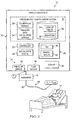
- FIGURE 1 illustrates an example breathing assistance system 10 for communicating gas to and/or from a patient, and for calculating and compensating for pressure drop associated with such gas communication, according to one embodiment of the disclosure.
- Breathing assistance system 10 may be generally configured to provide breathing assistance (e.g., providing ventilation and/or treating an apnea or other breathing condition) to a patient 11.
- Breathing assistance system 10 may include a ventilation system 12 and a connection system 14 for connecting ventilation system 12 to patient 11.
- Ventilation system 12 may comprise any device, apparatus, or system for delivering breathing gas to a patient, e.g., a ventilator, a respirator, a CPAP device, or a BiPAP device.
- Connection system 14 may be generally configured to deliver gas from ventilation system 12 to patient 11 and/or to communicate exhaust gas away from patient 11.
- connection system 14 may comprise any suitable type of breathing circuit (e.g., a single-limb or dual-limb circuit) and/or a patient connection apparatus.
- connection system 14 may include a 6-foot patient circuit.
- a patient connection apparatus may include any device or devices configured to connect the breathing circuit to one or more breathing passageways of patient 11.
- the patient connection apparatus may include a patient connection tube directly connected to the patient's trachea, an artificial airway (e.g., an endotracheal tube or other device) inserted in the patient's trachea, and/or a mask, cushion or nasal pillows positioned over the patient's nose and/or mouth.
- an artificial airway e.g., an endotracheal tube or other device
- a mask, cushion or nasal pillows positioned over the patient's nose and/or mouth.
- Ventilation system 12 may include a gas delivery system 20, a controller 22, one or more sensors 24, user interfaces 26, a display system 28, and a pressure drop compensation system 30.
- Gas delivery system 20 may include any device or devices configured to generate, supply, and/or deliver gas (e.g., pressurized air) toward patient 11 via connection system 14.
- gas delivery system 20 may comprise a device capable of generating pressurized air (e.g., a motorized blower or piston-based device), a wall outlet through which pressurized air may be supplied (e.g., in a hospital or clinic), valves configured to control the supply of gas to the patient (e.g., a PSOL or other solenoid valve), one or more tanks of compressed gas, a compressor, or any other suitable source of pressurized or non-pressurized gas.
- a device capable of generating pressurized air e.g., a motorized blower or piston-based device
- a wall outlet through which pressurized air may be supplied e.g., in a hospital or clinic
- valves configured to control the supply of gas to the patient (e.g., a PSOL or other solenoid valve), one or more tanks of compressed
- gas delivery system 20 in cooperation with other components of ventilation system 12 (e.g., an exhalation valve) may generate both positive and negative gas flows toward patient 11.
- a positive gas flow may be generated as gas is delivered to patient 11 during inhalation, while a negative gas flow may be generated as exhaust gas is communicated from patient 11 during exhalation.
- gas may refer to any one or more gases and/or vaporized substances suitable to be delivered to and/or from a patient via one or more breathing orifices (e.g., the nose and/or mouth), such as air, nitrogen, oxygen, any other component of air, CO 2 , vaporized water, vaporized medicines, and/or any combination of two or more of the above, for example.
- breathing orifices e.g., the nose and/or mouth
- patient may refer to any person or animal that may receive breathing assistance from system 10, regardless of the medical status, official patient status, physical location, or any other characteristic of the person.
- patients may include persons under official medical care (e.g., hospital patients), persons not under official medical care, persons receiving care at a medical care facility, persons receiving home care, etc.
- Controller 22 may be operable to control gas delivery system 20 to control the delivery of gas to and/or from patient 11 based on various input received from a user (e.g., via a touch screen and/or other user interfaces provided by ventilation system 12), data received from pressure drop compensation system 30, and/or data received from one or more sensors 24.
- controller 22 may regulate the pressure and/or flow rate of gas delivered to and/or from a patient based at least on pressure and/or flow data received from sensors 24 and pressure drop data received from pressure drop compensation system 30.
- Controller 22 may include, or have access to, one or more processors, memory devices, and any other suitable hardware or software.
- the one or more memory devices may store instructions (e.g., any suitable software, algorithms, or other logic or instructions that may be executed by one or more processors) for automatically controlling the operation of ventilation system 12 (e.g., controlling the pressure and/or flow rate output by gas delivery system 20) based on any of the various input data discussed herein.
- sensors 24 may be provided for sensing, detecting, and/or monitoring one or more parameters related to the ventilation of patient 11, e.g., parameters regarding the ventilation provided by ventilation system 12 and/or physiological parameters regarding patient 11.
- sensors 24 may include one or more devices for measuring various parameters of gas flowing to or from patient 11 or ventilation system 12, e.g., the pressure, flow rate, flow volume, temperature, gas content, and/or humidity of such gas flow.
- sensors 24 may include a pressure sensor 34 and a flow sensor 36 for measuring the pressure and flow, respectively, of gas delivered from gas delivery system 20.
- Sensors 34 and 36 may be located at any suitable location in system 10.
- each sensor 24 may be integrated with or coupled to ventilation system 12, integrated with or coupled to connection system 14, coupled to patient 11, or otherwise associated with system 10.
- pressure sensor 34 is located at or proximate a gas outlet of ventilation system 12 (e.g., at or proximate an outlet of gas delivery system 20).
- pressure sensor 34 may be located inside or just outside a housing or enclosure of ventilation system 12.
- pressure sensor 34 may be positioned to measure the pressure of gas flow exiting ventilation system 12 or gas delivery system 20, or the pressure of gas flow entering connection system 14, as generally indicated by arrow "P1" in FIGURE 1 .
- flow sensor 36 may be located at or proximate a gas outlet of ventilation system 12 (e.g., at or proximate an outlet of gas delivery system 20).
- flow sensor 36 may be located inside or just outside a housing or enclosure of ventilation system 12.
- flow sensor 36 may be positioned to measure the flow rate of gas flow exiting ventilation system 12 or gas delivery system 20, or the flow rate of gas flow entering connection system 14.
- breathing assistance system 10 may include a humidifier 70, which may be integral with or separate from, ventilation system 12.
- the humidifier may be located and connected to system 10 in any suitable manner.
- the humidifier 70 is located between the gas delivery system of the ventilation system 12 and the patient.
- humidifier 70 is located downstream of pressure sensor 34, and may affect (e.g., increase) the pressure drop between pressure sensor 34 and the patient end of connection system 14.
- Humidifier 70 may include any known type of humidifier for use with a ventilator, CPAP system, or other type of breathing assistance system 10.
- User interfaces 26 may include any suitable device or devices allowing a user to interface with breathing assistance system 10, e.g., to control ventilation system 12, to navigate through various display screens, to make selections, and/or to set, modify, or otherwise control various parameters regarding system 10.
- user interfaces 26 may allow a user to input desired performance parameters (e.g., pressure or flow rate) that may be communicated to controller 22 to control the operation of gas delivery system 20 and/or other components of system 10.
- GUI 40 may include a touch screen configured to display various information and provide an interface for accepting input from user (e.g., to navigate through various screens, to make selections, to set or modify various parameters, to change or configure the display, etc.).
- Manual input devices 42 may include any physical buttons, knobs, dials, switches, levers, or any other devices that may be manipulated by a user.
- Display device 28 may comprise a screen or any other device suitable for visually displaying medical data.
- display device 28 may include a monitor, an LCD screen, LEDs, or any other visual device.
- display device 28 and user interfaces 26 may be at least partially integrated, e.g., where ventilation system 12 includes a touch screen or other GUI 40.
- Pressure drop compensation system 30 may be generally configured to calculate the pressure drop of gas flowing through an apparatus of system 10 (e.g., connection system 14 or a portion thereof) such that controller 22 may compensate for such pressure drop in controlling or regulating gas delivery system 20.
- Pressure drop compensation system 30 may include a calibration module 50, a pressure drop calculation module 52, and one or more look-up tables 54 and/or equations 56 stored in memory 58.
- Calibration module 50 is generally configured to calibrate an apparatus 60 of system 10 for pressure drop calculations.
- Apparatus 60 may comprise any one or more components of system 10 in which gas may experience a pressure drop.
- apparatus 60 may comprise connection system 14 or a portion thereof, e.g., a patient circuit or patient hose with or without an attached patient connection apparatus (e.g., as defined above), with or without an attached humidifier 70, or any combination of such components.
- Calibration module 50 may be configured to perform one or more calibration tests for a particular type or a particular instance of an apparatus 60 in order to generate look-up tables 54 and/or equations 56 stored in memory 58.
- calibration module 50 may calibrate apparatus 60 during a calibration mode performed before connecting patient 11 to connection system 14 and/or before providing breathing assistance to patient 11. In other embodiments, e.g., where calibration data is preloaded into memory 58, calibration module 50 may not be included.
- Look-up tables 54 and/or equations 56 include data that may be used by pressure drop calculation module 52 for calculating a pressure drop in apparatus 60 while providing breathing assistance to patient 11.
- look-up tables 54 and/or equations 56 may be preloaded into memory 58.
- look-up tables 54 and/or equations 56 may be generated by calibration module 50, as discussed above.
- Equations 56 may include:
- Equations 56 may be used to calculate or estimate pressure drop for positive and/or negative flow rates through apparatus 60 (e.g., in some configurations, a negative flow rate may be experienced during exhalation). In some embodiments, the same equations 56 may be used for both positive and negative flow situations. In other embodiments, separate equations 56 may be used for positive and negative flow situations. For example, Equations (1) through (6b) provided below include separate equations 56 for positive and negative flow situations.
- Look-up tables 54 may include, for example, coefficients for any of equations 56.
- a l ook-up table 54 may include coefficients defining each of multiple (e.g., 80) different linear line segments that collectively approximate a non-linear function between pressure drop and flow rate. Such coefficients in look-up tables 54 may be easily accessed and used for calculating or estimating the pressure drop or mask pressure while providing breathing assistance to a patient 11.
- look-up tables 54 may include different tables corresponding to different types and/or configurations of apparatuses 60.
- look-up tables 54 may include a first table of equation coefficients for use with a 6' patient circuit and a second table of equation coefficients for use with an 8' patient circuit.
- look-up tables 54 may include a first table of equation coefficients for a configuration using a 6' patient circuit and including a humidifier 70, and a second table of equation coefficients for a configuration using the same 6' patient circuit, but not including a humidifier 70.
- look-up tables 54 may include one set of equation coefficients for positive flow situations and another set of equation coefficients for negative flow situations.
- different equations 56 may be used for positive and negative flow situations (e.g., Equations (1) through (6b) provided below)
- the same set of equation coefficient may be used for both positive and negative flow situations.
- Pressure drop calculation module 52 may be configured to use look-up tables 54 and/or equations 56 stored in memory 58, along with any other suitable data (e.g., data from sensors 24) for calculating a pressure drop in apparatus 60, e.g., while providing breathing assistance to patient 11.
- pressure drop calculation module 52 may use one or more equations 56 and/or equation coefficients store in a look-up table 54 to calculate pressure drop in apparatus 60 based on measured flow rate values received from flow sensor 36.
- Calibration module 50 and/or pressure drop calculation module 52 may include, or have access to, one or more processors (e.g., a microprocessor, a microcontroller, DSP, ASIC, FPGA, or any other suitable processor), tangible memory devices (e.g., RAM, DRAM, ROM, EPROM, Flash memory, one or more hard disks, and/or any other memory or storage device), and any other suitable hardware, software, or firmware.
- processors e.g., a microprocessor, a microcontroller, DSP, ASIC, FPGA, or any other suitable processor
- tangible memory devices e.g., RAM, DRAM, ROM, EPROM, Flash memory, one or more hard disks, and/or any other memory or storage device
- the one or more memory devices may store instructions (e.g., any suitable software, algorithms, or other logic or instructions that may be executed by one or more processors) for providing any of the functionality of such modules discussed herein.
- Calibration module 50 is configured to calibrate a particular type, configuration, or instance of apparatus 60 by performing multiple pressure drop calibration tests and determining equation coefficients for multiple straight line segments approximating a non-linear relationship between pressure drop through apparatus 60 and flow rate through apparatus 60.
- Each calibration test may include determining a pressure drop in gas flowing through apparatus 60 at a particular flow rate.
- Each calibration test may include delivering air through apparatus 60 with the distal end of apparatus 60 (i.e., opposite the end connected to ventilation system 12) left open such that the pressure at the distal end is atmospheric pressure, as indicated in FIGURE 1 as P 0 .
- the pressure P 1 measured adjacent the outlet of ventilation system 12 may be recorded as the pressure drop through apparatus 60.
- Calibration module 50 may perform calibration tests at any number of different flow rates, which may include positive flow rates, negative flow rates, or both. For example, calibration module 50 may perform calibration tests at 10 or more different flow rates to obtain 10 or more corresponding pressure drop values. In certain embodiments, calibration module 50 may perform about 80 calibration tests at 80 different flow rates to obtain 80 corresponding pressure drop values.
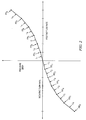
- FIGURE 2 illustrates an example plot of the results of calibration tests of an apparatus 60 at six positive flow rates (providing pressure drop data points PD 1 through PD 6 ) and six negative flow rates (providing pressure drop data points PD 1 ' through PD 6 ').
- calibration tests may be performed and recorded using both positive and negative flow rates. In other embodiments, calibration tests may be performed and recorded using positive flow rates, and the results may simply be mirrored to provide the negative flow rate test results, which may reduce the total number of calibration tests by half.
- the pressure drop data points may indicate a non-linear relationship between pressure drop and flow rate.
- calibration module 50 may determine six pairs of coefficients A i and B i , each coefficient pair corresponding to one of the six lines L 1 through L 6 . These coefficient pairs may be stored in a look-up table 54 for use by pressure drop calculation module 52 to calculate estimated mask pressure values based on flow rate values measured by flow sensor 36 while providing breathing assistance to a patient 11. As discussed below, these coefficient pairs may be used to calculate estimated mask pressure values for both positive flow and negative flow situations.
- multiple look-up tables 54 may be generated and/or maintained in memory 58, corresponding to any number of different types, configurations, or instances of apparatus 60.
- Pressure drop calculation module 52 may access the appropriate look-up tables 54 based on input received from a user (e.g., via a user selection of a particular configuration or type of patient circuit) or automatically via other components of ventilation system 12 and/or connection system 14 (e.g., ventilation system 12 may automatically identify the particular type of patient circuit connected to ventilation system 12, or whether a humidifier is connected to ventilation system 12, and send appropriate signals to pressure drop calculation module 52.
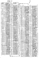
- FIGURE 3 illustrates an example look-up table 54 including 80 coefficient pairs for 80 line segments, for an example in which apparatus 60 comprises a 6 foot patient hose without a humidifier, according to an example embodiment of the disclosure.
- the coefficient pairs in look-up table 54 may be used for calculating pressure drops in both positive flow and negative flow situations. For example, the same coefficient pair may be used for a measured flow rate of 1.5 1/s and a measured flow rate of -1.5 1/s.
- calibration module 50 in ventilation system 12 may perform the calibration process discussed above for a particular apparatus 60 connected to ventilation system 12, and store the results in one or more look-up tables 54.
- ventilation system 12 may be used to calibrate a particular type, configuration, and/or instance of apparatus 60 to be used for providing breathing assistance to a patient 11.
- Such calibration may be performed at any suitable time prior to providing breathing assistance to a patient 11, e.g., just prior to initiating breathing assistance to patient 11, upon the initial configuration of ventilation system 12, or upon receiving a new type of apparatus 60 (e.g., a new brand or model of patient circuit).
- the calibration process discussed above may be performed on another ventilation system or during manufacturing of ventilation system 12, and look-up tables 54 may be pre-loaded into memory 58 in ventilation system 12.
- one or more look-up tables 54 may be pre-loaded into memory 58, but calibration module 50 may subsequently be used to generate and store additional look-up tables 54 (e.g., for new types or configurations of apparatus 60).
- calibration module 50 may calculate or determine a non-linear function between pressure drop through apparatus 60 and flow rate through apparatus 60.
- calibration module 50 may generate one or more non-linear equation(s) that approximates the relationship between pressure drop and flow rate using some or all of the calibration test data points.
- Such non-linear equation(s) may include equations of any order (e.g., second order, third order, fourth order, etc.), which order may be selected by a user or selected automatically by calibration module 50.
- Calibration module 50 may generate such non-linear equation(s) using any known curve-fitting techniques or other suitable techniques.
- Calibration module 50 is further configured to automatically calibrate a particular type, configuration, or instance of apparatus 60 by generating a non-linear function between pressure drop through apparatus 60 and flow rate through apparatus 60, and determining equation coefficients for multiple straight line segments approximating the generated non-linear function.
- the pressure drop in gas flowing through apparatus 60 e.g., due to resistance and variances associated with apparatus 60
- Pressure Drop Function Flow
- FIGURE 4 is a graph 120 illustrating example empirical results obtained from testing two configurations of apparatus 60 -- a 6' patient circuit without a humidifier and the 6' patient circuit with an attached humidifier -- which illustrates the non-linear nature of the relationship between pressure drop and flow rate.
- graph 120 only shows results for positive flow rates, similar results (but mirrored across the x- and y-axes) may be obtained for negative flow rates.
- Calibration module 50 may solve for coefficients X and Y in Equation (5) by performing one or more pressure drop calibration tests at one or more positive and/or negative flow rates. Such calibration tests may be performed as discussed above, e.g., by delivering air through apparatus 60 with the distal end of apparatus 60 (i.e., opposite the end connected to ventilation system 12) left open such that the pressure at the distal end is atmospheric pressure, as indicated in FIGURE 1 as P 0 .
- Equation (5) including coefficients X and Y solved based on the calibration test(s), may be stored in memory 58. With coefficients X and Y being solved, Equation (5) may be used either directly or indirectly for calculating mask pressure values based on positive and/or negative flow rate values measured by flow sensor 36 while providing breathing assistance to a patient 11, as discussed below.
- pressure drop calculation module 52 may use Equation (5) (including solved coefficients X and Y) directly for calculating estimated mask pressure values.
- Flow sensor 36 may measure and communicate flow rate values while providing breathing assistance to a patient 11.
- Pressure drop calculation module 52 may plug the flow rate values directly into Equation (5) to calculate estimated pressure drop values.
- Equation (5) may be substituted into Equation (3a) to obtain Equation (6a):
- Estimated Mask Pressure Measured P 1 - X * Flow 2 + Y * Flow
- pressure drop calculation module 52 may plug received flow rate values directly into Equation (6a) to directly calculate estimated mask pressure values in positive flow situations.
- Equation (5) may be substituted into Equation (3b) to obtain Equation (6b):
- Estimated Mask Pressure Measured P 1 + X * Flow 2 + Y * ABS Flow
- pressure drop calculation module 52 may plug received flow rate values directly into Equation (6b) to directly calculate estimated mask pressure values in negative flow situations.
- Equation (5) (including solved coefficients X and Y) may be used indirectly for calculating estimated mask pressure values.
- calibration module 50 may approximate the non-linear relationship between pressure drop and flow rate defined by Equation (5) using a number (e.g., 80) straight line segments.
- Calibration module 50 may calculate coefficients for equations representing each of such straight line segments, and store such coefficients in a look-up table 54.
- calibration module 50 may calculate coefficient pairs A i and B i for Equations (3a) and (3b) corresponding to each line segment.
- Estimated Mask Pressure Measured P 1 - A i * Flow + B i
- Estimated Mask Pressure Measured P 1 + A i * ABS Flow + B i
- Calibration module 50 may use any known or suitable techniques for calculating the coefficient pairs A i and B i for the line segments approximating the non-linear curve defined by Equation (5). For example, calibration module 50 may determine the slope of the curve defined by Equation (5) at each of a number (e.g., 80) of flow rate values, record the corresponding slopes as A i for each respective flow rate value (or for the data intervals corresponding to each respective flow rate value), and calculate the corresponding B i values.
- a number e.g. 80
- calibration module 50 may calculate the pressure drop values for each of a number (e.g., 80) of flow rate values according to Equation (5), and use each adjacent pair of calculated pressure drop values as end-points for the multiple (e.g., 80) line segments collectively approximating the curve of Equation (5).
- such calculated coefficient pairs A i and B i may be stored in a look-up table 54. Later, while providing breathing assistance to patient 11, pressure drop calculation module 52 may access such look-up table 54 to calculate estimated mask pressure values based on flow rate values measured by flow sensor 36 using Equation (3a) (for positive flow rates) or Equation (3b) (for negative flow rates).
- Ventilation system 12 may initiate any of the calibration processes discusses above in various manners.
- ventilation system 12 may allow the user to initiate a calibration of an apparatus 60 connected to ventilation system 12.
- ventilation system 12 may include one or more user interfaces 26 (e.g., GUI 40 or one or more manual input devices 42) allowing the user to (a) initiate an automatic calibration of apparatus 60, (b) initiate a line segment calibration of apparatus 60, (c) instruct the ventilation system 12 to access stored look-up tables 54 and/or equations 56 for a particular apparatus 60, and/or (d) enter data identifying apparatus 60 (e.g., the type of patient circuit and/or whether a humidifier is attached).
- GUI 40 e.g., GUI 40 or one or more manual input devices 42
- ventilation system 12 may include an "auto calibration” button and a "line segment calibration” button for initiating such calibration processes.
- a user interface 26 may allow the user to select various parameters for a calibration process, e.g., a number of calibration tests to be performed, a range of flow rates for the calibration tests, a number of line segments to be calculated, and/or an order of a non-linear equation (e.g., third order equation) to be calculated (e.g., by curve fitting) to approximate the calibration test data.
- GUI 40 may include any suitable buttons and/or menus for selecting and/or inputting any of the parameters discussed above.
- ventilation system 12 may be configured to automatically access the appropriate look-up tables 54 and/or equations 56 based on data entered by the user identifying apparatus 60 (e.g., a serial number, part number, or type of patient circuit and/or whether a humidifier is attached). In other embodiments, ventilation system 12 may be configured to automatically obtain identification information regarding apparatus 60, and access the corresponding look-up tables 54 and/or equations 56. For example, ventilation system 12 may be configured to automatically read data stored in non-volatile memory embedded in a patient circuit when the patient circuit is connected to ventilation system 12. In such embodiments, ventilation system 12 may calibrate an apparatus 60, or access the appropriate look-up tables 54 and/or equations 56, automatically without user input.
- data entered by the user identifying apparatus 60 e.g., a serial number, part number, or type of patient circuit and/or whether a humidifier is attached.
- ventilation system 12 may be configured to automatically obtain identification information regarding apparatus 60, and access the corresponding look-up tables 54 and/or equations 56.
- ventilation system 12
Landscapes
- Health & Medical Sciences (AREA)
- Emergency Medicine (AREA)
- Pulmonology (AREA)
- Engineering & Computer Science (AREA)
- Anesthesiology (AREA)
- Biomedical Technology (AREA)
- Heart & Thoracic Surgery (AREA)
- Hematology (AREA)
- Life Sciences & Earth Sciences (AREA)
- Animal Behavior & Ethology (AREA)
- General Health & Medical Sciences (AREA)
- Public Health (AREA)
- Veterinary Medicine (AREA)
- Measurement Of The Respiration, Hearing Ability, Form, And Blood Characteristics Of Living Organisms (AREA)
Claims (10)
- Dispositif d'assistance respiratoire configuré pour déterminer une chute de pression, comprenant :- un dispositif de ventilation (12) ; et- un appareil de raccordement à un patient (60) configuré pour fournir du gaz du dispositif de ventilation (12) à un patient (11) ;dans lequel le dispositif de ventilation (12) comprend :- un dispositif de fourniture de gaz (20) configuré pour fournir du gaz à un patient (11) ;- au moins un capteur de pression (34) et au moins un capteur de débit (36) pour mesurer la pression et le débit de gaz fourni par le dispositif de fourniture de gaz (20) ; et- un dispositif de compensation de chute de pression (30) couplé de manière fonctionnelle auxdits capteurs de pression et de débit (34, 36), comprenant un module d'étalonnage (50) et un module de calcul de chute de pression (52) et configuré pour :effectuer un ou plusieurs tests d'étalonnage de chute de pression pendant lesquels une extrémité distale dudit appareil de raccordement à un patient (60) est laissée ouverte, chaque test d'étalonnage de chute de pression mesurant une chute de pression dans un gaz s'écoulant à travers ledit appareil de raccordement à un patient (60) à un débit particulier ;dans lequel le dispositif de compensation de chute de pression (30) est configuré pour fonctionner suivant un mode d'étalonnage automatique dans lequel, sur la base au moins des résultats du ou de plusieurs tests d'étalonnage de chute de pression, le module d'étalonnage (50) fonctionne pour déterminer et enregistrer les coefficients d'une équation non linéaire se rapprochant d'un rapport entre la chute de pression et le débit du gaz s'écoulant à travers le dispositif d'assistance respiratoire ;dans lequel le module de calcul de chute de pression (52) est configuré pour déterminer les chutes de pression du gaz s'écoulant à travers le dispositif d'assistance respiratoire pour divers débits sur la base de l'équation non linéaire,caractérisé en ce quele dispositif de compensation de chute de pression (30) est en outre configuré pour fonctionner suivant un mode d'étalonnage par segments de droite dans lequel, sur la base au moins des résultats du ou de plusieurs tests d'étalonnage de chute de pression, le module d'étalonnage (50) fonctionne pour déterminer et enregistrer dans un tableau de correspondances les coefficients pour de multiples segments de droite linéaires, dans lequel chaque segment de droite est déterminé par l'un desdits tests d'étalonnage de chute de pression dans lequel un débit et une pression associée sont déterminés par lesdits capteurs (34, 36), les multiples segments de droite linéaires se rapprochant collectivement du rapport non linéaire entre la chute de pression et le débit du gaz s'écoulant à travers le dispositif d'assistance respiratoire, dans lequel il peut être accédé aux coefficients calculés pour déterminer des chutes de pression du gaz s'écoulant à travers l'appareil du dispositif d'assistance respiratoire pour divers débits, etle dispositif de ventilation (12) comprend en outre une interface utilisateur (26) pour sélectionner soit ledit mode d'étalonnage automatique, soit ledit mode d'étalonnage par segments de droite.
- Dispositif d'assistance respiratoire selon la revendication 1, dans lequel l'équation non linéaire est définie par :

où F désigne le débit et X et Y désignent des coefficients déterminés par lesdits tests d'étalonnage de chute de pression. - Dispositif d'assistance respiratoire selon la revendication 1 ou 2, dans lequel les coefficients des segments de droite définissent une pente d'une courbe.
- Dispositif d'assistance respiratoire selon la revendication 1 ou 2, dans lequel un segment de droite est déterminé par des points d'extrémité et dans lequel les points d'extrémité sont déterminés par lesdits tests d'étalonnage de chute de pression.
- Dispositif d'assistance respiratoire selon l'une des revendications précédentes, dans lequel chaque segment de droite est défini par l'équation linéaire suivante :

où i désigne le numéro de segment de droite, F est le débit et A et B sont des coefficients déterminés par ladite équation de chute de pression. - Dispositif d'assistance respiratoire selon l'une des revendications précédentes, dans lequel environ 80 tests d'étalonnage de chute de pression sont effectués.
- Dispositif d'assistance respiratoire selon l'une des revendications précédentes, dans lequel le module de calcul de chute de pression (52) détermine une pression de masque estimée en compensant une pression mesurée à un débit actuel avec une chute de pression audit débit mesuré déterminé par ledit mode d'étalonnage automatique, ou ledit module d'étalonnage par segments de droite.
- Dispositif d'assistance respiratoire selon l'une quelconque des revendications précédentes, dans lequel l'interface utilisateur (26) permet à l'utilisateur d'ordonner au dispositif de ventilation (12) d'accéder aux tableaux de correspondances enregistrés et/ou aux équations enregistrées pour un appareil (60) particulier.
- Dispositif d'assistance respiratoire selon la revendication 8, dans lequel ladite interface utilisateur est configurée en outre pour permettre à un utilisateur de sélectionner les paramètres d'un étalonnage sélectionné.
- Dispositif d'assistance respiratoire selon la revendication 9, dans lequel lesdits paramètres sont sélectionnés parmi au moins l'un parmi : un nombre de tests d'étalonnage, une plage de débits, un nombre de segments de droite et un ordre d'une équation non linéaire.
Priority Applications (2)
| Application Number | Priority Date | Filing Date | Title |
|---|---|---|---|
| EP08006240.9A EP2106818B1 (fr) | 2008-03-31 | 2008-03-31 | Système de compensation pour une chute de pression dans un système d'assistance respiratoire |
| US12/410,310 US8353291B2 (en) | 2008-03-31 | 2009-03-24 | Systems and methods for compensating for pressure drop in a breathing assistance system |
Applications Claiming Priority (1)
| Application Number | Priority Date | Filing Date | Title |
|---|---|---|---|
| EP08006240.9A EP2106818B1 (fr) | 2008-03-31 | 2008-03-31 | Système de compensation pour une chute de pression dans un système d'assistance respiratoire |
Publications (2)
| Publication Number | Publication Date |
|---|---|
| EP2106818A1 EP2106818A1 (fr) | 2009-10-07 |
| EP2106818B1 true EP2106818B1 (fr) | 2013-12-25 |
Family
ID=39618909
Family Applications (1)
| Application Number | Title | Priority Date | Filing Date |
|---|---|---|---|
| EP08006240.9A Not-in-force EP2106818B1 (fr) | 2008-03-31 | 2008-03-31 | Système de compensation pour une chute de pression dans un système d'assistance respiratoire |
Country Status (2)
| Country | Link |
|---|---|
| US (1) | US8353291B2 (fr) |
| EP (1) | EP2106818B1 (fr) |
Families Citing this family (111)
| Publication number | Priority date | Publication date | Assignee | Title |
|---|---|---|---|---|
| US5881723A (en) | 1997-03-14 | 1999-03-16 | Nellcor Puritan Bennett Incorporated | Ventilator breath display and graphic user interface |
| FR2858236B1 (fr) | 2003-07-29 | 2006-04-28 | Airox | Dispositif et procede de fourniture de gaz respiratoire en pression ou en volume |
| US8021310B2 (en) | 2006-04-21 | 2011-09-20 | Nellcor Puritan Bennett Llc | Work of breathing display for a ventilation system |
| US7784461B2 (en) | 2006-09-26 | 2010-08-31 | Nellcor Puritan Bennett Llc | Three-dimensional waveform display for a breathing assistance system |
| EP2313138B1 (fr) | 2008-03-31 | 2018-09-12 | Covidien LP | Système et procédé pour déterminer une fuite de système de ventilation pendant des périodes stables lors d'une respiration |
| US8746248B2 (en) | 2008-03-31 | 2014-06-10 | Covidien Lp | Determination of patient circuit disconnect in leak-compensated ventilatory support |
| US8272379B2 (en) | 2008-03-31 | 2012-09-25 | Nellcor Puritan Bennett, Llc | Leak-compensated flow triggering and cycling in medical ventilators |
| US8267085B2 (en) | 2009-03-20 | 2012-09-18 | Nellcor Puritan Bennett Llc | Leak-compensated proportional assist ventilation |
| US8792949B2 (en) | 2008-03-31 | 2014-07-29 | Covidien Lp | Reducing nuisance alarms |
| CN102056538B (zh) | 2008-06-06 | 2014-10-15 | 柯惠有限合伙公司 | 用于在换气系统中确定患者努力及/或呼吸参数的系统及方法 |
| WO2010028150A1 (fr) | 2008-09-04 | 2010-03-11 | Nellcor Puritan Bennett Llc | Ventilateur avec fonction de purge commandée |
| US8551006B2 (en) | 2008-09-17 | 2013-10-08 | Covidien Lp | Method for determining hemodynamic effects |
| US8424520B2 (en) | 2008-09-23 | 2013-04-23 | Covidien Lp | Safe standby mode for ventilator |
| CA2736540C (fr) | 2008-09-25 | 2015-11-24 | Nellcor Puritan Bennett Llc | Compensation par action directe a base d'inversion d'une dynamique de declencheur inspiratoire dans des ventilateurs medicaux |
| US8181648B2 (en) | 2008-09-26 | 2012-05-22 | Nellcor Puritan Bennett Llc | Systems and methods for managing pressure in a breathing assistance system |
| WO2010039884A1 (fr) | 2008-09-30 | 2010-04-08 | Nellcor Puritan Bennett Llc | Détecteur d'inclinaison pneumatique pour une utilisation avec un dispositif de détection de débit respiratoire |
| US8302602B2 (en) | 2008-09-30 | 2012-11-06 | Nellcor Puritan Bennett Llc | Breathing assistance system with multiple pressure sensors |
| US8393323B2 (en) | 2008-09-30 | 2013-03-12 | Covidien Lp | Supplemental gas safety system for a breathing assistance system |
| US8424521B2 (en) | 2009-02-27 | 2013-04-23 | Covidien Lp | Leak-compensated respiratory mechanics estimation in medical ventilators |
| US8418691B2 (en) | 2009-03-20 | 2013-04-16 | Covidien Lp | Leak-compensated pressure regulated volume control ventilation |
| US8776790B2 (en) | 2009-07-16 | 2014-07-15 | Covidien Lp | Wireless, gas flow-powered sensor system for a breathing assistance system |
| US8789529B2 (en) | 2009-08-20 | 2014-07-29 | Covidien Lp | Method for ventilation |
| US8469030B2 (en) | 2009-12-01 | 2013-06-25 | Covidien Lp | Exhalation valve assembly with selectable contagious/non-contagious latch |
| US8439036B2 (en) | 2009-12-01 | 2013-05-14 | Covidien Lp | Exhalation valve assembly with integral flow sensor |
| US8469031B2 (en) | 2009-12-01 | 2013-06-25 | Covidien Lp | Exhalation valve assembly with integrated filter |
| EP4215234A1 (fr) | 2009-12-01 | 2023-07-26 | Fisher & Paykel Healthcare Limited | Appareil d'assistance respiratoire |
| US8439037B2 (en) | 2009-12-01 | 2013-05-14 | Covidien Lp | Exhalation valve assembly with integrated filter and flow sensor |
| US8421465B2 (en) | 2009-12-02 | 2013-04-16 | Covidien Lp | Method and apparatus for indicating battery cell status on a battery pack assembly used during mechanical ventilation |
| US8434484B2 (en) | 2009-12-03 | 2013-05-07 | Covidien Lp | Ventilator Respiratory Variable-Sized Gas Accumulator |
| US9119925B2 (en) | 2009-12-04 | 2015-09-01 | Covidien Lp | Quick initiation of respiratory support via a ventilator user interface |
| USD649157S1 (en) | 2009-12-04 | 2011-11-22 | Nellcor Puritan Bennett Llc | Ventilator display screen with a user interface |
| US8924878B2 (en) | 2009-12-04 | 2014-12-30 | Covidien Lp | Display and access to settings on a ventilator graphical user interface |
| US8335992B2 (en) | 2009-12-04 | 2012-12-18 | Nellcor Puritan Bennett Llc | Visual indication of settings changes on a ventilator graphical user interface |
| US8418692B2 (en) | 2009-12-04 | 2013-04-16 | Covidien Lp | Ventilation system with removable primary display |
| US9814851B2 (en) | 2009-12-04 | 2017-11-14 | Covidien Lp | Alarm indication system |
| USD638852S1 (en) | 2009-12-04 | 2011-05-31 | Nellcor Puritan Bennett Llc | Ventilator display screen with an alarm icon |
| US8499252B2 (en) | 2009-12-18 | 2013-07-30 | Covidien Lp | Display of respiratory data graphs on a ventilator graphical user interface |
| US9262588B2 (en) | 2009-12-18 | 2016-02-16 | Covidien Lp | Display of respiratory data graphs on a ventilator graphical user interface |
| US20110152697A1 (en) * | 2009-12-18 | 2011-06-23 | K&Y Corporation | Circulatory Pressure Monitoring Using Infusion Pump Systems |
| JP2013514836A (ja) | 2009-12-18 | 2013-05-02 | ケーアンドワイ コーポレイション | 注入ポンプ |
| US20110146683A1 (en) * | 2009-12-21 | 2011-06-23 | Nellcor Puritan Bennett Llc | Sensor Model |
| RU2567461C2 (ru) * | 2009-12-21 | 2015-11-10 | Конинклейке Филипс Электроникс Н.В. | Автоматическая идентификация устройства интерфейса пациента в ситеме поддержания давления |
| US8400290B2 (en) | 2010-01-19 | 2013-03-19 | Covidien Lp | Nuisance alarm reduction method for therapeutic parameters |
| US8707952B2 (en) | 2010-02-10 | 2014-04-29 | Covidien Lp | Leak determination in a breathing assistance system |
| US9302061B2 (en) | 2010-02-26 | 2016-04-05 | Covidien Lp | Event-based delay detection and control of networked systems in medical ventilation |
| US8453643B2 (en) | 2010-04-27 | 2013-06-04 | Covidien Lp | Ventilation system with system status display for configuration and program information |
| US8511306B2 (en) | 2010-04-27 | 2013-08-20 | Covidien Lp | Ventilation system with system status display for maintenance and service information |
| US8539949B2 (en) | 2010-04-27 | 2013-09-24 | Covidien Lp | Ventilation system with a two-point perspective view |
| US8638200B2 (en) | 2010-05-07 | 2014-01-28 | Covidien Lp | Ventilator-initiated prompt regarding Auto-PEEP detection during volume ventilation of non-triggering patient |
| US8607791B2 (en) | 2010-06-30 | 2013-12-17 | Covidien Lp | Ventilator-initiated prompt regarding auto-PEEP detection during pressure ventilation |
| US8607790B2 (en) | 2010-06-30 | 2013-12-17 | Covidien Lp | Ventilator-initiated prompt regarding auto-PEEP detection during pressure ventilation of patient exhibiting obstructive component |
| US8607788B2 (en) | 2010-06-30 | 2013-12-17 | Covidien Lp | Ventilator-initiated prompt regarding auto-PEEP detection during volume ventilation of triggering patient exhibiting obstructive component |
| US8607789B2 (en) | 2010-06-30 | 2013-12-17 | Covidien Lp | Ventilator-initiated prompt regarding auto-PEEP detection during volume ventilation of non-triggering patient exhibiting obstructive component |
| US8676285B2 (en) | 2010-07-28 | 2014-03-18 | Covidien Lp | Methods for validating patient identity |
| US8554298B2 (en) | 2010-09-21 | 2013-10-08 | Cividien LP | Medical ventilator with integrated oximeter data |
| US8757152B2 (en) | 2010-11-29 | 2014-06-24 | Covidien Lp | Ventilator-initiated prompt regarding detection of double triggering during a volume-control breath type |
| US8595639B2 (en) | 2010-11-29 | 2013-11-26 | Covidien Lp | Ventilator-initiated prompt regarding detection of fluctuations in resistance |
| US8757153B2 (en) | 2010-11-29 | 2014-06-24 | Covidien Lp | Ventilator-initiated prompt regarding detection of double triggering during ventilation |
| US8676529B2 (en) | 2011-01-31 | 2014-03-18 | Covidien Lp | Systems and methods for simulation and software testing |
| US8788236B2 (en) | 2011-01-31 | 2014-07-22 | Covidien Lp | Systems and methods for medical device testing |
| US8783250B2 (en) | 2011-02-27 | 2014-07-22 | Covidien Lp | Methods and systems for transitory ventilation support |
| US9038633B2 (en) | 2011-03-02 | 2015-05-26 | Covidien Lp | Ventilator-initiated prompt regarding high delivered tidal volume |
| US8714154B2 (en) | 2011-03-30 | 2014-05-06 | Covidien Lp | Systems and methods for automatic adjustment of ventilator settings |
| US8776792B2 (en) | 2011-04-29 | 2014-07-15 | Covidien Lp | Methods and systems for volume-targeted minimum pressure-control ventilation |
| US9629971B2 (en) | 2011-04-29 | 2017-04-25 | Covidien Lp | Methods and systems for exhalation control and trajectory optimization |
| DE11005677T1 (de) * | 2011-07-12 | 2013-07-25 | Healthc'air | Verfahren zur Erzeugung eines angemessenen Drucks für einen Gasdurchsatzgenerator |
| US9089657B2 (en) | 2011-10-31 | 2015-07-28 | Covidien Lp | Methods and systems for gating user initiated increases in oxygen concentration during ventilation |
| US9364624B2 (en) | 2011-12-07 | 2016-06-14 | Covidien Lp | Methods and systems for adaptive base flow |
| US9498589B2 (en) | 2011-12-31 | 2016-11-22 | Covidien Lp | Methods and systems for adaptive base flow and leak compensation |
| US9022031B2 (en) | 2012-01-31 | 2015-05-05 | Covidien Lp | Using estimated carinal pressure for feedback control of carinal pressure during ventilation |
| US9327089B2 (en) | 2012-03-30 | 2016-05-03 | Covidien Lp | Methods and systems for compensation of tubing related loss effects |
| US8844526B2 (en) | 2012-03-30 | 2014-09-30 | Covidien Lp | Methods and systems for triggering with unknown base flow |
| US9993604B2 (en) | 2012-04-27 | 2018-06-12 | Covidien Lp | Methods and systems for an optimized proportional assist ventilation |
| US9144658B2 (en) | 2012-04-30 | 2015-09-29 | Covidien Lp | Minimizing imposed expiratory resistance of mechanical ventilator by optimizing exhalation valve control |
| US10362967B2 (en) | 2012-07-09 | 2019-07-30 | Covidien Lp | Systems and methods for missed breath detection and indication |
| US9027552B2 (en) | 2012-07-31 | 2015-05-12 | Covidien Lp | Ventilator-initiated prompt or setting regarding detection of asynchrony during ventilation |
| CN104717995B (zh) * | 2012-10-10 | 2017-12-29 | 皇家飞利浦有限公司 | 利用在面罩装置处的压力传感器的自适应患者回路补偿 |
| US9375542B2 (en) | 2012-11-08 | 2016-06-28 | Covidien Lp | Systems and methods for monitoring, managing, and/or preventing fatigue during ventilation |
| US9289573B2 (en) | 2012-12-28 | 2016-03-22 | Covidien Lp | Ventilator pressure oscillation filter |
| US9492629B2 (en) | 2013-02-14 | 2016-11-15 | Covidien Lp | Methods and systems for ventilation with unknown exhalation flow and exhalation pressure |
| USD731049S1 (en) | 2013-03-05 | 2015-06-02 | Covidien Lp | EVQ housing of an exhalation module |
| USD736905S1 (en) | 2013-03-08 | 2015-08-18 | Covidien Lp | Exhalation module EVQ housing |
| USD731048S1 (en) | 2013-03-08 | 2015-06-02 | Covidien Lp | EVQ diaphragm of an exhalation module |
| USD701601S1 (en) | 2013-03-08 | 2014-03-25 | Covidien Lp | Condensate vial of an exhalation module |
| USD693001S1 (en) | 2013-03-08 | 2013-11-05 | Covidien Lp | Neonate expiratory filter assembly of an exhalation module |
| USD744095S1 (en) | 2013-03-08 | 2015-11-24 | Covidien Lp | Exhalation module EVQ internal flow sensor |
| USD692556S1 (en) | 2013-03-08 | 2013-10-29 | Covidien Lp | Expiratory filter body of an exhalation module |
| USD731065S1 (en) | 2013-03-08 | 2015-06-02 | Covidien Lp | EVQ pressure sensor filter of an exhalation module |
| US9358355B2 (en) | 2013-03-11 | 2016-06-07 | Covidien Lp | Methods and systems for managing a patient move |
| US9981096B2 (en) | 2013-03-13 | 2018-05-29 | Covidien Lp | Methods and systems for triggering with unknown inspiratory flow |
| US9950135B2 (en) | 2013-03-15 | 2018-04-24 | Covidien Lp | Maintaining an exhalation valve sensor assembly |
| US10064583B2 (en) | 2013-08-07 | 2018-09-04 | Covidien Lp | Detection of expiratory airflow limitation in ventilated patient |
| US9995645B2 (en) * | 2013-10-18 | 2018-06-12 | Silverbow Development, Llc | Techniques for determining patient airway pressure |
| US9675771B2 (en) | 2013-10-18 | 2017-06-13 | Covidien Lp | Methods and systems for leak estimation |
| US9808591B2 (en) | 2014-08-15 | 2017-11-07 | Covidien Lp | Methods and systems for breath delivery synchronization |
| US9950129B2 (en) | 2014-10-27 | 2018-04-24 | Covidien Lp | Ventilation triggering using change-point detection |
| US10722670B2 (en) * | 2014-10-28 | 2020-07-28 | Fisher & Paykel Healthcare Limited | Patient specific auto-flowrate control |
| US9925346B2 (en) | 2015-01-20 | 2018-03-27 | Covidien Lp | Systems and methods for ventilation with unknown exhalation flow |
| USD775345S1 (en) | 2015-04-10 | 2016-12-27 | Covidien Lp | Ventilator console |
| CN107847699A (zh) * | 2015-06-30 | 2018-03-27 | 皇家飞利浦有限公司 | 用于可变阻力气道正压设备管路补偿的气压传感器 |
| US10765822B2 (en) | 2016-04-18 | 2020-09-08 | Covidien Lp | Endotracheal tube extubation detection |
| EP3525857B1 (fr) | 2017-11-14 | 2020-01-29 | Covidien LP | Systèmes de ventilation spontanée par pression de commande |
| US20190201647A1 (en) * | 2017-12-28 | 2019-07-04 | Koninklijke Philips N.V. | System and method for providing high-flow nasal therapy |
| EP4045122B1 (fr) * | 2019-10-14 | 2025-11-26 | ResMed Pty Ltd | Systèmes de caractérisation pour thérapie respiratoire |
| US11672934B2 (en) | 2020-05-12 | 2023-06-13 | Covidien Lp | Remote ventilator adjustment |
| CN113842528B (zh) * | 2020-06-28 | 2023-08-22 | 南京理工大学 | 一种压差控制的高流量通气方法和系统 |
| US20220362496A1 (en) * | 2021-05-14 | 2022-11-17 | Telesair, Inc. | Method for controlling oxygen-containing gas and related products |
| US12465716B2 (en) * | 2021-07-01 | 2025-11-11 | Sunil Nanda | Ventilator |
| WO2023049958A1 (fr) * | 2021-09-29 | 2023-04-06 | ResMed Pty Ltd | Systèmes de caractérisation pour thérapie respiratoire |
| CN113877031A (zh) * | 2021-09-30 | 2022-01-04 | 深圳市科曼医疗设备有限公司 | 呼吸机泄漏流速计算方法、装置、计算机设备及存储介质 |
| WO2026003680A1 (fr) * | 2024-06-27 | 2026-01-02 | Fisher & Paykel Healthcare Limited | Appareil respiratoire et système de distribution de gaz |
Family Cites Families (33)
| Publication number | Priority date | Publication date | Assignee | Title |
|---|---|---|---|---|
| US710341A (en) * | 1900-08-15 | 1902-09-30 | William H Rymer | Bucket or manger. |
| US5099836A (en) | 1987-10-05 | 1992-03-31 | Hudson Respiratory Care Inc. | Intermittent oxygen delivery system and cannula |
| FI82367C (fi) | 1988-02-11 | 1991-03-11 | Instrumentarium Oy | Till intubationsroer kopplad spirometer och provtagningsfoerbindning i gasanalysator. |
| GB8824865D0 (en) | 1988-10-24 | 1988-11-30 | Antec Systems | Gas sampling device & water trap |
| US4967744A (en) | 1988-11-03 | 1990-11-06 | Airoflex Medical, Inc. | Flexible breathing circuit |
| US5259373A (en) | 1989-05-19 | 1993-11-09 | Puritan-Bennett Corporation | Inspiratory airway pressure system controlled by the detection and analysis of patient airway sounds |
| US5370122A (en) | 1992-11-18 | 1994-12-06 | Kunig; Horst E. | Method and apparatus for measuring myocardial impairment, dysfunctions, sufficiency, and insufficiency |
| DE4329898A1 (de) | 1993-09-04 | 1995-04-06 | Marcus Dr Besson | Kabelloses medizinisches Diagnose- und Überwachungsgerät |
| US5494051A (en) | 1994-09-14 | 1996-02-27 | Cardi-Act, L.L.C. | Patient-transport apparatus |
| US5551419A (en) * | 1994-12-15 | 1996-09-03 | Devilbiss Health Care, Inc. | Control for CPAP apparatus |
| US5969429A (en) | 1997-08-15 | 1999-10-19 | The United States Of America As Represented By The Secretary Of The Navy | Breathing apparatus having electrical power supply arrangement with turbine-generator assembly |
| US6135106A (en) | 1997-08-22 | 2000-10-24 | Nellcor Puritan-Bennett, Inc. | CPAP pressure and flow transducer |
| US7658891B1 (en) | 1997-11-21 | 2010-02-09 | Barnes Ronald L | Air purification and decontamination for hazmat suits |
| US7739061B2 (en) | 1999-02-12 | 2010-06-15 | Pierre Bonnat | Method and system for controlling a user interface of a device using human breath |
| WO2001078593A1 (fr) * | 2000-04-17 | 2001-10-25 | Nellcor Puritan Bennett Incorporated | Capteur sphygmo-oxymetre avec fonction en pas a pas |
| SE0002449D0 (sv) * | 2000-06-29 | 2000-06-29 | Siemens Elema Ab | Method and arrangement for evaluating effective flow resistance of a patient breathing circuit |
| WO2002053217A1 (fr) * | 2000-12-29 | 2002-07-11 | Resmed Ltd. | Caracterisation de systemes de masques respiratoires |
| EP1228779A1 (fr) | 2001-02-01 | 2002-08-07 | Instrumentarium Corporation | Méthode et dispositif pour déterminer un état de flux gazeux zéro dans une conduite bidirectionnelle de gaz |
| FR2824907A1 (fr) | 2001-05-21 | 2002-11-22 | Taema | Systeme et procede auto-alimente de surveillance de canalisation ou d'appareil pneumatique |
| FR2829942A1 (fr) | 2001-09-27 | 2003-03-28 | Taema | Appareil et procede de ventilation artificielle avec systeme de mesure de debit de gaz inspiratoire et expiratoire |
| US7438073B2 (en) * | 2002-03-08 | 2008-10-21 | Kaerys S.A. | Air assistance apparatus for computing the airflow provided by only means of pressure sensors |
| US20080021339A1 (en) | 2005-10-27 | 2008-01-24 | Gabriel Jean-Christophe P | Anesthesia monitor, capacitance nanosensors and dynamic sensor sampling method |
| US7089930B2 (en) | 2002-08-20 | 2006-08-15 | Audiopack Technologies, Inc. | Wireless heads-up display for a self-contained breathing apparatus |
| US7101341B2 (en) | 2003-04-15 | 2006-09-05 | Ross Tsukashima | Respiratory monitoring, diagnostic and therapeutic system |
| CN1933874B (zh) | 2004-04-05 | 2012-02-01 | 矿井安全装置公司 | 用于从容器里储存的在压力下的气体产生电的设备、系统和方法 |
| US20070100222A1 (en) | 2004-06-14 | 2007-05-03 | Metronic Minimed, Inc. | Analyte sensing apparatus for hospital use |
| CA2577867A1 (fr) | 2004-08-27 | 2006-03-09 | Johns Hopkins University | Dispositif de surveillance de sommeil et de respiration jetable |
| US7451762B2 (en) | 2005-06-17 | 2008-11-18 | Salter Labs | Pressure sensing device with test circuit |
| EP2063945B1 (fr) | 2006-09-07 | 2019-07-03 | ResMed Ltd. | Masque et système générateur de flux |
| US7985254B2 (en) | 2007-01-08 | 2011-07-26 | David Tolkowsky | Endobronchial fluid exhaler devices and methods for use thereof |
| DE102007007969B4 (de) | 2007-02-17 | 2020-07-09 | Drägerwerk AG & Co. KGaA | Patientenverbindung für die maschinelle Beatmung eines Patienten |
| AU2008203812B2 (en) | 2007-08-17 | 2014-10-02 | ResMed Pty Ltd | Methods and Apparatus for Pressure Therapy in the Treatment of Sleep Disordered Breathing |
| EP2349421B1 (fr) | 2008-09-10 | 2019-10-30 | ResMed Pty Ltd | Amélioration de la gestion de la puissance dans un appareil de traitement respiratoire |
-
2008
- 2008-03-31 EP EP08006240.9A patent/EP2106818B1/fr not_active Not-in-force
-
2009
- 2009-03-24 US US12/410,310 patent/US8353291B2/en not_active Expired - Fee Related
Also Published As
| Publication number | Publication date |
|---|---|
| US20090241952A1 (en) | 2009-10-01 |
| EP2106818A1 (fr) | 2009-10-07 |
| US8353291B2 (en) | 2013-01-15 |
Similar Documents
| Publication | Publication Date | Title |
|---|---|---|
| EP2106818B1 (fr) | Système de compensation pour une chute de pression dans un système d'assistance respiratoire | |
| US8720442B2 (en) | Systems and methods for managing pressure in a breathing assistance system | |
| US8312879B2 (en) | Method and apparatus for airway compensation control | |
| US7987847B2 (en) | Characterisation of mask systems | |
| JP4307811B2 (ja) | 呼吸システムの肺力学の検査のためのオペレーティングシステムおよび呼吸装置システム | |
| JP4938185B2 (ja) | 患者呼吸回路の有効流れ抵抗を評価するための方法及び装置 | |
| US20240075226A1 (en) | System and method for accurate estimation of intentional and unintentional leaks in flow generation systems | |
| US20130012828A1 (en) | Method and System for Measuring Nasal Resistance to Airflow | |
| US20110146681A1 (en) | Adaptive Flow Sensor Model | |
| JP2009500124A (ja) | モジュール型補充気体調整器及びそれを使用する呼吸治療装置 | |
| TWI902240B (zh) | 用於提供氣泡持續氣道正壓(cpap)的呼吸系統 | |
| US20210052839A1 (en) | Anterior interface pressure monitoring during ventilation | |
| US11433198B2 (en) | Methods and apparatus for flow therapy | |
| US20220096764A1 (en) | Synchronized high-flow system | |
| US20120053481A1 (en) | Method and system for measuring nasal resistance to airflow |
Legal Events
| Date | Code | Title | Description |
|---|---|---|---|
| PUAI | Public reference made under article 153(3) epc to a published international application that has entered the european phase |
Free format text: ORIGINAL CODE: 0009012 |
|
| AK | Designated contracting states |
Kind code of ref document: A1 Designated state(s): AT BE BG CH CY CZ DE DK EE ES FI FR GB GR HR HU IE IS IT LI LT LU LV MC MT NL NO PL PT RO SE SI SK TR |
|
| AX | Request for extension of the european patent |
Extension state: AL BA MK RS |
|
| 17P | Request for examination filed |
Effective date: 20100322 |
|
| 17Q | First examination report despatched |
Effective date: 20100414 |
|
| AKX | Designation fees paid |
Designated state(s): AT BE BG CH CY CZ DE DK EE ES FI FR GB GR HR HU IE IS IT LI LT LU LV MC MT NL NO PL PT RO SE SI SK TR |
|
| GRAP | Despatch of communication of intention to grant a patent |
Free format text: ORIGINAL CODE: EPIDOSNIGR1 |
|
| INTG | Intention to grant announced |
Effective date: 20130726 |
|
| GRAS | Grant fee paid |
Free format text: ORIGINAL CODE: EPIDOSNIGR3 |
|
| GRAA | (expected) grant |
Free format text: ORIGINAL CODE: 0009210 |
|
| AK | Designated contracting states |
Kind code of ref document: B1 Designated state(s): AT BE BG CH CY CZ DE DK EE ES FI FR GB GR HR HU IE IS IT LI LT LU LV MC MT NL NO PL PT RO SE SI SK TR |
|
| REG | Reference to a national code |
Ref country code: GB Ref legal event code: FG4D |
|
| REG | Reference to a national code |
Ref country code: CH Ref legal event code: EP |
|
| REG | Reference to a national code |
Ref country code: AT Ref legal event code: REF Ref document number: 646231 Country of ref document: AT Kind code of ref document: T Effective date: 20140115 |
|
| REG | Reference to a national code |
Ref country code: IE Ref legal event code: FG4D |
|
| REG | Reference to a national code |
Ref country code: DE Ref legal event code: R096 Ref document number: 602008029478 Country of ref document: DE Effective date: 20140213 |
|
| PG25 | Lapsed in a contracting state [announced via postgrant information from national office to epo] |
Ref country code: HR Free format text: LAPSE BECAUSE OF FAILURE TO SUBMIT A TRANSLATION OF THE DESCRIPTION OR TO PAY THE FEE WITHIN THE PRESCRIBED TIME-LIMIT Effective date: 20131225 Ref country code: LT Free format text: LAPSE BECAUSE OF FAILURE TO SUBMIT A TRANSLATION OF THE DESCRIPTION OR TO PAY THE FEE WITHIN THE PRESCRIBED TIME-LIMIT Effective date: 20131225 Ref country code: NO Free format text: LAPSE BECAUSE OF FAILURE TO SUBMIT A TRANSLATION OF THE DESCRIPTION OR TO PAY THE FEE WITHIN THE PRESCRIBED TIME-LIMIT Effective date: 20140325 Ref country code: SE Free format text: LAPSE BECAUSE OF FAILURE TO SUBMIT A TRANSLATION OF THE DESCRIPTION OR TO PAY THE FEE WITHIN THE PRESCRIBED TIME-LIMIT Effective date: 20131225 Ref country code: FI Free format text: LAPSE BECAUSE OF FAILURE TO SUBMIT A TRANSLATION OF THE DESCRIPTION OR TO PAY THE FEE WITHIN THE PRESCRIBED TIME-LIMIT Effective date: 20131225 |
|
| REG | Reference to a national code |
Ref country code: NL Ref legal event code: VDEP Effective date: 20131225 |
|
| REG | Reference to a national code |
Ref country code: AT Ref legal event code: MK05 Ref document number: 646231 Country of ref document: AT Kind code of ref document: T Effective date: 20131225 |
|
| REG | Reference to a national code |
Ref country code: LT Ref legal event code: MG4D |
|
| PG25 | Lapsed in a contracting state [announced via postgrant information from national office to epo] |
Ref country code: LV Free format text: LAPSE BECAUSE OF FAILURE TO SUBMIT A TRANSLATION OF THE DESCRIPTION OR TO PAY THE FEE WITHIN THE PRESCRIBED TIME-LIMIT Effective date: 20131225 |
|
| PG25 | Lapsed in a contracting state [announced via postgrant information from national office to epo] |
Ref country code: BE Free format text: LAPSE BECAUSE OF FAILURE TO SUBMIT A TRANSLATION OF THE DESCRIPTION OR TO PAY THE FEE WITHIN THE PRESCRIBED TIME-LIMIT Effective date: 20131225 Ref country code: EE Free format text: LAPSE BECAUSE OF FAILURE TO SUBMIT A TRANSLATION OF THE DESCRIPTION OR TO PAY THE FEE WITHIN THE PRESCRIBED TIME-LIMIT Effective date: 20131225 Ref country code: IS Free format text: LAPSE BECAUSE OF FAILURE TO SUBMIT A TRANSLATION OF THE DESCRIPTION OR TO PAY THE FEE WITHIN THE PRESCRIBED TIME-LIMIT Effective date: 20140425 |
|
| PG25 | Lapsed in a contracting state [announced via postgrant information from national office to epo] |
Ref country code: PT Free format text: LAPSE BECAUSE OF FAILURE TO SUBMIT A TRANSLATION OF THE DESCRIPTION OR TO PAY THE FEE WITHIN THE PRESCRIBED TIME-LIMIT Effective date: 20140428 Ref country code: PL Free format text: LAPSE BECAUSE OF FAILURE TO SUBMIT A TRANSLATION OF THE DESCRIPTION OR TO PAY THE FEE WITHIN THE PRESCRIBED TIME-LIMIT Effective date: 20131225 Ref country code: CY Free format text: LAPSE BECAUSE OF FAILURE TO SUBMIT A TRANSLATION OF THE DESCRIPTION OR TO PAY THE FEE WITHIN THE PRESCRIBED TIME-LIMIT Effective date: 20131225 Ref country code: ES Free format text: LAPSE BECAUSE OF FAILURE TO SUBMIT A TRANSLATION OF THE DESCRIPTION OR TO PAY THE FEE WITHIN THE PRESCRIBED TIME-LIMIT Effective date: 20131225 Ref country code: AT Free format text: LAPSE BECAUSE OF FAILURE TO SUBMIT A TRANSLATION OF THE DESCRIPTION OR TO PAY THE FEE WITHIN THE PRESCRIBED TIME-LIMIT Effective date: 20131225 Ref country code: CZ Free format text: LAPSE BECAUSE OF FAILURE TO SUBMIT A TRANSLATION OF THE DESCRIPTION OR TO PAY THE FEE WITHIN THE PRESCRIBED TIME-LIMIT Effective date: 20131225 Ref country code: SK Free format text: LAPSE BECAUSE OF FAILURE TO SUBMIT A TRANSLATION OF THE DESCRIPTION OR TO PAY THE FEE WITHIN THE PRESCRIBED TIME-LIMIT Effective date: 20131225 Ref country code: RO Free format text: LAPSE BECAUSE OF FAILURE TO SUBMIT A TRANSLATION OF THE DESCRIPTION OR TO PAY THE FEE WITHIN THE PRESCRIBED TIME-LIMIT Effective date: 20131225 Ref country code: NL Free format text: LAPSE BECAUSE OF FAILURE TO SUBMIT A TRANSLATION OF THE DESCRIPTION OR TO PAY THE FEE WITHIN THE PRESCRIBED TIME-LIMIT Effective date: 20131225 |
|
| REG | Reference to a national code |
Ref country code: DE Ref legal event code: R097 Ref document number: 602008029478 Country of ref document: DE |
|
| PG25 | Lapsed in a contracting state [announced via postgrant information from national office to epo] |
Ref country code: DK Free format text: LAPSE BECAUSE OF FAILURE TO SUBMIT A TRANSLATION OF THE DESCRIPTION OR TO PAY THE FEE WITHIN THE PRESCRIBED TIME-LIMIT Effective date: 20131225 Ref country code: LU Free format text: LAPSE BECAUSE OF FAILURE TO SUBMIT A TRANSLATION OF THE DESCRIPTION OR TO PAY THE FEE WITHIN THE PRESCRIBED TIME-LIMIT Effective date: 20140331 |
|
| PLBE | No opposition filed within time limit |
Free format text: ORIGINAL CODE: 0009261 |
|
| REG | Reference to a national code |
Ref country code: CH Ref legal event code: PL |
|
| STAA | Information on the status of an ep patent application or granted ep patent |
Free format text: STATUS: NO OPPOSITION FILED WITHIN TIME LIMIT |
|
| 26N | No opposition filed |
Effective date: 20140926 |
|
| REG | Reference to a national code |
Ref country code: IE Ref legal event code: MM4A |
|
| REG | Reference to a national code |
Ref country code: DE Ref legal event code: R097 Ref document number: 602008029478 Country of ref document: DE Effective date: 20140926 |
|
| PG25 | Lapsed in a contracting state [announced via postgrant information from national office to epo] |
Ref country code: LI Free format text: LAPSE BECAUSE OF NON-PAYMENT OF DUE FEES Effective date: 20140331 Ref country code: IE Free format text: LAPSE BECAUSE OF NON-PAYMENT OF DUE FEES Effective date: 20140331 Ref country code: CH Free format text: LAPSE BECAUSE OF NON-PAYMENT OF DUE FEES Effective date: 20140331 |
|
| PG25 | Lapsed in a contracting state [announced via postgrant information from national office to epo] |
Ref country code: SI Free format text: LAPSE BECAUSE OF FAILURE TO SUBMIT A TRANSLATION OF THE DESCRIPTION OR TO PAY THE FEE WITHIN THE PRESCRIBED TIME-LIMIT Effective date: 20131225 |
|
| REG | Reference to a national code |
Ref country code: FR Ref legal event code: PLFP Year of fee payment: 9 |
|
| PG25 | Lapsed in a contracting state [announced via postgrant information from national office to epo] |
Ref country code: MT Free format text: LAPSE BECAUSE OF FAILURE TO SUBMIT A TRANSLATION OF THE DESCRIPTION OR TO PAY THE FEE WITHIN THE PRESCRIBED TIME-LIMIT Effective date: 20131225 |
|
| PG25 | Lapsed in a contracting state [announced via postgrant information from national office to epo] |
Ref country code: MC Free format text: LAPSE BECAUSE OF FAILURE TO SUBMIT A TRANSLATION OF THE DESCRIPTION OR TO PAY THE FEE WITHIN THE PRESCRIBED TIME-LIMIT Effective date: 20131225 Ref country code: BG Free format text: LAPSE BECAUSE OF FAILURE TO SUBMIT A TRANSLATION OF THE DESCRIPTION OR TO PAY THE FEE WITHIN THE PRESCRIBED TIME-LIMIT Effective date: 20131225 |
|
| PG25 | Lapsed in a contracting state [announced via postgrant information from national office to epo] |
Ref country code: GR Free format text: LAPSE BECAUSE OF FAILURE TO SUBMIT A TRANSLATION OF THE DESCRIPTION OR TO PAY THE FEE WITHIN THE PRESCRIBED TIME-LIMIT Effective date: 20140326 Ref country code: IT Free format text: LAPSE BECAUSE OF FAILURE TO SUBMIT A TRANSLATION OF THE DESCRIPTION OR TO PAY THE FEE WITHIN THE PRESCRIBED TIME-LIMIT Effective date: 20131225 |
|
| PG25 | Lapsed in a contracting state [announced via postgrant information from national office to epo] |
Ref country code: TR Free format text: LAPSE BECAUSE OF FAILURE TO SUBMIT A TRANSLATION OF THE DESCRIPTION OR TO PAY THE FEE WITHIN THE PRESCRIBED TIME-LIMIT Effective date: 20131225 Ref country code: HU Free format text: LAPSE BECAUSE OF FAILURE TO SUBMIT A TRANSLATION OF THE DESCRIPTION OR TO PAY THE FEE WITHIN THE PRESCRIBED TIME-LIMIT; INVALID AB INITIO Effective date: 20080331 |
|
| REG | Reference to a national code |
Ref country code: FR Ref legal event code: PLFP Year of fee payment: 10 |
|
| REG | Reference to a national code |
Ref country code: FR Ref legal event code: PLFP Year of fee payment: 11 |
|
| PGFP | Annual fee paid to national office [announced via postgrant information from national office to epo] |
Ref country code: FR Payment date: 20200220 Year of fee payment: 13 |
|
| PG25 | Lapsed in a contracting state [announced via postgrant information from national office to epo] |
Ref country code: FR Free format text: LAPSE BECAUSE OF NON-PAYMENT OF DUE FEES Effective date: 20210331 |
|
| PGFP | Annual fee paid to national office [announced via postgrant information from national office to epo] |
Ref country code: DE Payment date: 20240220 Year of fee payment: 17 Ref country code: GB Payment date: 20240221 Year of fee payment: 17 |
|
| REG | Reference to a national code |
Ref country code: DE Ref legal event code: R119 Ref document number: 602008029478 Country of ref document: DE |
|
| GBPC | Gb: european patent ceased through non-payment of renewal fee |
Effective date: 20250331 |
|
| PG25 | Lapsed in a contracting state [announced via postgrant information from national office to epo] |
Ref country code: DE Free format text: LAPSE BECAUSE OF NON-PAYMENT OF DUE FEES Effective date: 20251001 |
|
| PG25 | Lapsed in a contracting state [announced via postgrant information from national office to epo] |
Ref country code: GB Free format text: LAPSE BECAUSE OF NON-PAYMENT OF DUE FEES Effective date: 20250331 |