EP2106846A1 - Raccordement de mélange - Google Patents
Raccordement de mélange Download PDFInfo
- Publication number
- EP2106846A1 EP2106846A1 EP08154104A EP08154104A EP2106846A1 EP 2106846 A1 EP2106846 A1 EP 2106846A1 EP 08154104 A EP08154104 A EP 08154104A EP 08154104 A EP08154104 A EP 08154104A EP 2106846 A1 EP2106846 A1 EP 2106846A1
- Authority
- EP
- European Patent Office
- Prior art keywords
- channel
- junction
- width
- plane
- height
- Prior art date
- Legal status (The legal status is an assumption and is not a legal conclusion. Google has not performed a legal analysis and makes no representation as to the accuracy of the status listed.)
- Withdrawn
Links
- 238000002156 mixing Methods 0.000 title claims abstract description 33
- 239000012530 fluid Substances 0.000 claims abstract description 56
- 238000000034 method Methods 0.000 claims abstract description 31
- 238000009792 diffusion process Methods 0.000 description 18
- 235000012431 wafers Nutrition 0.000 description 15
- 239000011521 glass Substances 0.000 description 12
- 239000003153 chemical reaction reagent Substances 0.000 description 11
- 238000004519 manufacturing process Methods 0.000 description 11
- 238000006243 chemical reaction Methods 0.000 description 10
- 238000005516 engineering process Methods 0.000 description 10
- 238000005530 etching Methods 0.000 description 7
- 239000000126 substance Substances 0.000 description 7
- 238000001020 plasma etching Methods 0.000 description 6
- 238000005422 blasting Methods 0.000 description 5
- 239000000843 powder Substances 0.000 description 5
- 238000001039 wet etching Methods 0.000 description 5
- WEVYAHXRMPXWCK-UHFFFAOYSA-N Acetonitrile Chemical compound CC#N WEVYAHXRMPXWCK-UHFFFAOYSA-N 0.000 description 4
- 230000008602 contraction Effects 0.000 description 4
- 238000013461 design Methods 0.000 description 4
- 230000000694 effects Effects 0.000 description 4
- 238000003786 synthesis reaction Methods 0.000 description 4
- 230000008901 benefit Effects 0.000 description 3
- 230000015572 biosynthetic process Effects 0.000 description 3
- 238000005553 drilling Methods 0.000 description 3
- 238000003801 milling Methods 0.000 description 3
- VYPSYNLAJGMNEJ-UHFFFAOYSA-N Silicium dioxide Chemical compound O=[Si]=O VYPSYNLAJGMNEJ-UHFFFAOYSA-N 0.000 description 2
- 238000004458 analytical method Methods 0.000 description 2
- FUSUHKVFWTUUBE-UHFFFAOYSA-N buten-2-one Chemical compound CC(=O)C=C FUSUHKVFWTUUBE-UHFFFAOYSA-N 0.000 description 2
- 238000001312 dry etching Methods 0.000 description 2
- 239000005350 fused silica glass Substances 0.000 description 2
- 230000014759 maintenance of location Effects 0.000 description 2
- 239000000463 material Substances 0.000 description 2
- 239000000203 mixture Substances 0.000 description 2
- 239000000376 reactant Substances 0.000 description 2
- 229910001220 stainless steel Inorganic materials 0.000 description 2
- 239000010935 stainless steel Substances 0.000 description 2
- 238000003756 stirring Methods 0.000 description 2
- 239000000758 substrate Substances 0.000 description 2
- 238000003631 wet chemical etching Methods 0.000 description 2
- XLEOCTUCGZANAC-UHFFFAOYSA-N 4-(diethylamino)butan-2-one Chemical compound CCN(CC)CCC(C)=O XLEOCTUCGZANAC-UHFFFAOYSA-N 0.000 description 1
- 238000009623 Bosch process Methods 0.000 description 1
- 230000004544 DNA amplification Effects 0.000 description 1
- 238000006845 Michael addition reaction Methods 0.000 description 1
- 238000012742 biochemical analysis Methods 0.000 description 1
- 238000005842 biochemical reaction Methods 0.000 description 1
- 239000003124 biologic agent Substances 0.000 description 1
- 238000004364 calculation method Methods 0.000 description 1
- 239000013043 chemical agent Substances 0.000 description 1
- 239000003795 chemical substances by application Substances 0.000 description 1
- 238000007796 conventional method Methods 0.000 description 1
- 238000011161 development Methods 0.000 description 1
- HPNMFZURTQLUMO-UHFFFAOYSA-N diethylamine Chemical compound CCNCC HPNMFZURTQLUMO-UHFFFAOYSA-N 0.000 description 1
- 238000009826 distribution Methods 0.000 description 1
- 230000007613 environmental effect Effects 0.000 description 1
- 238000002032 lab-on-a-chip Methods 0.000 description 1
- 239000007788 liquid Substances 0.000 description 1
- 239000012528 membrane Substances 0.000 description 1
- 238000012986 modification Methods 0.000 description 1
- 230000004048 modification Effects 0.000 description 1
- 238000012544 monitoring process Methods 0.000 description 1
- 239000006174 pH buffer Substances 0.000 description 1
- 230000021715 photosynthesis, light harvesting Effects 0.000 description 1
- 230000001737 promoting effect Effects 0.000 description 1
- 238000013341 scale-up Methods 0.000 description 1
- 238000012216 screening Methods 0.000 description 1
Images

Classifications
-
- B—PERFORMING OPERATIONS; TRANSPORTING
- B01—PHYSICAL OR CHEMICAL PROCESSES OR APPARATUS IN GENERAL
- B01F—MIXING, e.g. DISSOLVING, EMULSIFYING OR DISPERSING
- B01F25/00—Flow mixers; Mixers for falling materials, e.g. solid particles
- B01F25/30—Injector mixers
- B01F25/31—Injector mixers in conduits or tubes through which the main component flows
- B01F25/314—Injector mixers in conduits or tubes through which the main component flows wherein additional components are introduced at the circumference of the conduit
-
- B—PERFORMING OPERATIONS; TRANSPORTING
- B01—PHYSICAL OR CHEMICAL PROCESSES OR APPARATUS IN GENERAL
- B01F—MIXING, e.g. DISSOLVING, EMULSIFYING OR DISPERSING
- B01F25/00—Flow mixers; Mixers for falling materials, e.g. solid particles
- B01F25/30—Injector mixers
- B01F25/31—Injector mixers in conduits or tubes through which the main component flows
- B01F25/314—Injector mixers in conduits or tubes through which the main component flows wherein additional components are introduced at the circumference of the conduit
- B01F25/3143—Injector mixers in conduits or tubes through which the main component flows wherein additional components are introduced at the circumference of the conduit characterised by the specific design of the injector
- B01F25/31432—Injector mixers in conduits or tubes through which the main component flows wherein additional components are introduced at the circumference of the conduit characterised by the specific design of the injector being a slit extending in the circumferential direction only
-
- B—PERFORMING OPERATIONS; TRANSPORTING
- B01—PHYSICAL OR CHEMICAL PROCESSES OR APPARATUS IN GENERAL
- B01F—MIXING, e.g. DISSOLVING, EMULSIFYING OR DISPERSING
- B01F25/00—Flow mixers; Mixers for falling materials, e.g. solid particles
- B01F25/40—Static mixers
- B01F25/45—Mixers in which the materials to be mixed are pressed together through orifices or interstitial spaces, e.g. between beads
-
- B—PERFORMING OPERATIONS; TRANSPORTING
- B01—PHYSICAL OR CHEMICAL PROCESSES OR APPARATUS IN GENERAL
- B01F—MIXING, e.g. DISSOLVING, EMULSIFYING OR DISPERSING
- B01F25/00—Flow mixers; Mixers for falling materials, e.g. solid particles
- B01F25/40—Static mixers
- B01F25/45—Mixers in which the materials to be mixed are pressed together through orifices or interstitial spaces, e.g. between beads
- B01F25/452—Mixers in which the materials to be mixed are pressed together through orifices or interstitial spaces, e.g. between beads characterised by elements provided with orifices or interstitial spaces
- B01F25/4521—Mixers in which the materials to be mixed are pressed together through orifices or interstitial spaces, e.g. between beads characterised by elements provided with orifices or interstitial spaces the components being pressed through orifices in elements, e.g. flat plates or cylinders, which obstruct the whole diameter of the tube
-
- B—PERFORMING OPERATIONS; TRANSPORTING
- B01—PHYSICAL OR CHEMICAL PROCESSES OR APPARATUS IN GENERAL
- B01F—MIXING, e.g. DISSOLVING, EMULSIFYING OR DISPERSING
- B01F33/00—Other mixers; Mixing plants; Combinations of mixers
- B01F33/30—Micromixers
Definitions
- the invention is directed to a process for mixing two or more streams in a microfluidic device and to a microfluidic mixer for carrying out said process, and to a microfluidic device comprising said microfluidic mixer.
- Microfluidics deals with the behaviour, precise control and manipulation of microliter to picoliter volumes of fluids. It is a multidisciplinary field intersecting engineering, physics, chemistry, microtechnology and biotechnology. Microfluidics is a relatively new field of technology and is used e . g . in the development of lab-on-a-chip technology. Microfluidics can be applied to a variety of technical areas including biochemical analysis, medical diagnostics, chemical synthesis, and environmental monitoring. For example, use of microfluidic systems for acquiring chemical and biological information presents certain advantages. In particular, microfluidic systems increase the response time of reactions and reduce reagent consumption.
- microfluidic volumes when conducted in microfluidic volumes, a large number of complicated biochemical reactions and/or processes may be carried out in a small area, such as in a single integrated device.
- Examples of desirable applications for microfluidic technology include analytical chemistry, chemical and biological synthesis, DNA amplification, and screening of chemical and biological agents i . a . for activity.
- microfluidic technology is of interest for microreactor chip technology.
- Microreactor chips are chips which are designed for the production of chemical substances. Such microreactor chips can be used, for instance, for the synthesis of chemical products which, for whatever reason, is impossible or unfavourable when using conventional batch technology. Examples thereof include very exothermic chemical reactions for which temperature control is very important.
- the behaviour of fluids at the microscale can differ from "macrofluidic" behaviour in that factors such as surface tension, energy dissipation, and fluidic resistance start to dominate the system.
- achieving effective mixing between two or more fluid streams is a relatively straightforward task.
- Various conventional strategies may be employed to induce turbulent regions that cause fluid streams to mix rapidly.
- active stirring or mixing elements e . g . mechanically or magnetically driving
- special geometries may be employed in flow channels to promote mixing without the use of moving elements.
- microfluidic systems are characterised by extremely high surface-to-volume ratios and correspondingly the Reynolds number, which characterises the presence of turbulent flow, is extremely low (typically less than 2 000) for most achievable fluid flow rates.
- Reynolds number typically less than 2 000
- fluid flow within most microfluidic systems is surely within the laminar regime, and mixing between fluid streams is motivated primarily by diffusion.
- using conventional geometric modifications such as baffles is generally ineffective for promoting mixing.
- the task of integrating moveable stirring elements and/or their drive means in microfluidic systems using conventional methods is extremely difficult due to volumetric and/or cost constraints, in addition to concerns regarding their complexity and reliability.
- WO-A-03/059498 describes a microfluidic device, which combines two fluid streams of reagents in a mixing channel. Subsequently, the combined stream is passed over a contraction/expansion region, which is said to promote mixing, in particular at high fluid flow rates and multiple contraction/expansion regions. Effective mixing according to this system only starts after the junction of the two fluid streams at the contraction/expansion region. In addition, effective mixing requires multiple contraction/expansion regions which considerably increase costs and volume on the microfluidic chip.
- WO-A-03/059499 describes a microfluidic device in which a first fluid stream of reagent flows from a first wide channel through a multiple of small apertures into a second wide channel to join a second fluid stream of reagent.
- the first fluid is divided into several sub-streams that appear as "streaks" in the second fluid, which are said to provide a large interfacial contact area between the two fluids and promote mixing.
- the diffusion distance of the first fluid in the direction perpendicular to the second fluid is relatively long.
- the first fluid also needs to diffuse in the direction parallel to the second fluid stream for complete mixing. This can be a rather slow process.
- the invention is directed to a process for mixing two or more fluid streams in a microfluidic device, comprising
- the invention is directed to a microfluidic mixer for carrying out the process of the invention, said mixer comprising a junction, which junction joins two or more channels, wherein the width and length of a first of said two or more channels define a plane and at least a second of said two or more channels lies out of said plane, said first channel having a height being smaller than the width of said first channel and which height is smaller than at least one dimension of said second channel, said dimension lying in said plane.
- the invention is directed to a microfluidic device comprising said microfluidic mixer.
- the present invention advantageously uses this relatively new field of technology to provide a highly effective way of mixing streams of fluids in a microfluidic device.
- microfluidic as used in this application is meant to refer to structures or devices through which fluid(s) are capable of being passed or directed, wherein one or more of the dimensions is less than 500 ⁇ m.
- length of a channel as used in this application is meant to refer to the largest dimension of the channel. Normally, the length of the channel is the direction of the channel in which fluid flows.
- width of a channel as used in this application is meant to refer to the largest dimension of the channel perpendicular to the length of the channel.
- the term "height of a channel” as used in this application is meant to refer to the dimension perpendicular to the length of the channel and perpendicular to the width of the channel.
- the invention involves a process for mixing two or more fluid streams in a microfluidic device.
- the microfluidic device can be any microfluidic device in which two or more fluid streams require effective mixing.
- the invention is advantageous when applied in a microreactor chip in which multiple reactants are mixed in order to react with each other. Depending on the reaction to be performed quick and effective mixing may be essential to achieve a satisfactory reaction and high through-put. Also chemical and biological analysis systems can benefit of the invention, where e . g . pH-buffers, markers or reagents need to be mixed with the chemical sample to achieve proper analysis.
- a very convenient and relatively cheap method of manufacturing microfluidic devices is by wet etching a specific channel structure in a wafer, such as a glass wafer, and subsequently covering the wet-etched glass with a cover wafer. This results in a microfluidic device having a two-dimensional channel structure.
- Wet-etching normally yields channels that have a width (in the plane of the wafer) which is at least two times the height (perpendicular to the plane of the wafer) of the channel. In practice, the width of the channels is often approximately at least five times the height of the channel.
- microfluidic devices where the microfluidic channels are divided over two or more planes, i . e . where three or more wafers, or other materials, are stacked, e . g . wafer bonding, wafer clamping, and wafers sealed with membranes.
- glass and stainless steel are the preferred materials for microfluidic devices for microreactor technology. Due to better chemical properties, the transparency and the smaller sizes of glass microfluidic devices over stainless steel microfluidic devices, glass is much more popular for fabrication of microfluidic devices.
- multistack bonding technology is used to achieve multistack glass microfluidic devices.
- Multistack bonding technology allows bonding more than two wafers (such as glass wafers). This allows for the manufacture of microfluidic devices having multiple floors with channel structures. Three-dimensional structures can be designed in which for instance channels run above each other. This enables the process in the microfluidic device to be parallelised, which is highly advantageous for instance to scale up synthetic reactions performed in a microfluidic device. At the same time such a three-dimensional channel design allows for a junction across different layers. Such a junction can be utilised for carrying out the invention.
- At least two fluid streams are provided. These streams can be gaseous or liquid.
- the streams can be reagents of a reaction (such as a synthetic reaction) to be performed in the microfluidic device.
- reagents can all be provided separately, but it is also possible that two or more reagents are provided as a mixture in one stream and another reagent is provided separately in another stream.
- the streams can be introduced in the microfluidic device through a number of inlets.
- the channels can have any shape.
- the cross-section of the channels can for instance be circular or semicircular, ellipsoidal or semi ellipsoidal, square, rectangular, or mixtures thereof.
- many microfluidic channels are prepared by wet etching of glass. This process has an isotropic character, giving rise to channels of which the cross-section always has a characteristic shape: two quarter circles at the edges and rectangular in the middle. The two quarter circles are a result of the etching agent (such as HF or BHF), which also causes channels prepared in this way to have a width which is at least twice the height of the channel.
- the etching agent such as HF or BHF
- At least a first channel has a length and a width that define a plane. This plane is usually the plane of the microfluidic device defined by the (multi)layer wafer structure.
- the first channel has a height (perpendicular to the plane defined by the length and width of the channel) which is smaller than the width of the channel.
- Such channels are easy and relatively cheap to produce according to the above described wet etching technique.
- the aspect ratio, defined as the ratio between the width of the channel and the height of the channel, of the first channel is preferably at least 2, more preferably at least 5, and even more preferably at least 10. From a technical point of view the aspect ratio is normally not more than 500, preferably not more than 100.
- the first channel enters a junction wherein the stream flowing through said first channel is joined with at least a second stream entering the junction.
- the junction can join two or more channels, such as 2, 3, 4, 5, 6, 7 or 8 channels. Junctions that join more than 8 channels are technically more difficult to produce, but are not excluded from the invention.
- a very convenient junction is a three-way junction such as an Y-junction or a T-junction, wherein one of the channels lies out of the plane defined by the length and the width of the first channel. In practice, the fabrication of T-junctions is less involved and these junctions are therefore preferred.
- a second channel enters the junction.
- This channel lies out of the plane defined by the length and the width of the first channel described above. Normally, this channel will also lie out of the plane of the microfluidic device (defined by the multilayer wafer structure).
- the angle between the second channel and the plane defined by the length and width of the first channel is not of particular importance and can for instance range from 10-170°.
- the angle of incidence of the second channel does not influence the diffusion length, because the angle does not determine the flow distribution of the combined stream in the mixing channel, where the actual mixing takes place.
- the second channel lying out of the plane is essentially perpendicular to the plane defined by the length and the width of the first channel.
- the second channel can be used to introduce a fluid stream (such as the second fluid stream) into the junction, but it can also be used as a mixing channel to carry off the combined stream of at least the first and the second fluid from the junction.
- a fluid stream such as the second fluid stream
- the second channel can be used to introduce a fluid stream (such as the second fluid stream) into the junction, but it can also be used as a mixing channel to carry off the combined stream of at least the first and the second fluid from the junction.
- the height of the first channel is smaller than the width of the first channel.
- the height of the first channel is smaller than at least one dimension of said second channel, wherein said dimension lies in the plane defined by the length and the width of the first channel.
- said at least one dimension is the width or height of said second channel.
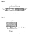
- the distance for diffusion for the different streams to mix is mainly determined by the width of the channel.
- This diffusion distance is relatively long compared to the junction utilised in the invention shown in Figure 1b .
- This embodiment shows a first channel having an aspect ratio similar to the channels shown in Figure la (thus the height of the first channel is smaller than the width of the first channel), which is joined with a second channel lying out of the plane defined by the length and width of the first channel.
- the height of the first channel is smaller than the width of the second channel.
- the distance for diffusion for the different streams to mix is in this way mainly determined by the height of the first channel.
- the distance for diffusion is much smaller than in the case of the conventional junction shown in Figure 1a .
- the effect of the invention is even more pronounced because the diffusion time increases quadratically with the diffusion distance.
- said second channel joins the first channel at the junction over at least the full width of the first channel, preferably over the full width. This has the effect that during mixing of the fluid streams, diffusion only has to take place in one dimension. In contrast, when the second channel joins the first channel at the junction over less than the full width of the first channel, diffusion must take place in two dimensions. In an embodiment, the dimension of the second channel in the direction of the width of the first channel corresponds to the width of the first channel.
- the channels lying in the plane defined by the length and width of the first channel will normally be manufactured by wet etching.
- other manufacturing methods are possible. Examples thereof include dry-etching such as (Deep) Reactive Ion Etching ((D)RIE), powder blasting, milling, drilling, and photon enhanced etching.
- dry-etching such as (Deep) Reactive Ion Etching ((D)RIE)
- powder blasting powder blasting
- milling milling
- drilling and photon enhanced etching.
- photon enhanced etching for glass structures wet-chemical etching and powder blasting are the common techniques due to economical reasons. Powder blasting gives the possibility for a fast and cheap way of etching glass structures, also with high aspect ratios.
- wet-chemical etching is the standard.
- Channels lying out of the plane defined by the length and width of the first channel will normally be manufactured by powder blasting.
- Other examples of fabrication processes include dry-etching such as (Deep) Reactive Ion Etching ((D)RIE), milling, drilling, and photon enhanced etching.
- DRIE Deep Reactive Ion Etching
- a disadvantage of using (D)RIE is that for instance glass is not easily processed with (D)RIE. It is a slow and costly process. In addition, it is believed that multiple runs are required for deep channels, due to deposits on the substrate during the process. This process (also known as the BOSCH-process) is therefore not commonly used for glass substrates. Photon etching is in principle also possible, but is rather costly. Furthermore, the manufacture of microchannels by milling or drilling can be technically difficult, in particular when the channels have very small dimensions.
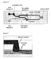
- the invention was successfully implemented in the parallel microreactor chip depicted in Figure 2 .
- This parallel microreactor chip was fabricated out of three fused silica wafers. The channels were wet-etched, the second channel in the mixer was powder-blasted and the three fused silica wafers were bonded together. The different channels and regions in the microreactor chip are indicated using dyed fluids.
- the microreactor chip has inlets on the left side, a set of meanders which are part of a flow splitter, where two channels are located above each other, a set of meanders on the right side which serve as microreactors and in the middle eight mixers where the two fluid streams are mixed. Two of these mixers are indicated by the circle.
- FIG. 3 is a schematic side view of the microreactor used
- Figure 4 which is a schematic top view of the microreactor used.
- Figure 5 A detailed schematic drawing of the used mixer is shown in Figure 5 .
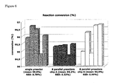
- the 8-parallel microreactor chip was used to perform a Michael addition reaction for the synthesis of 4-(diethylamino)butan-2-one from methyl vinyl ketone and diethylamine.
- Figure 6 shows the obtained conversion results.
- CDue to the use of the invented mixer no additional mixers were necessary to obtain a conversion of 96 % can be achieved in a microreactor with a cross section of 60 ⁇ m ⁇ 300 ⁇ m without additional mixers within a total retention time (including mixing time) of only 7.2 seconds. Using conventional mixers this would not have been possible.
Landscapes
- Chemical & Material Sciences (AREA)
- Chemical Kinetics & Catalysis (AREA)
- Dispersion Chemistry (AREA)
- Physical Or Chemical Processes And Apparatus (AREA)
Priority Applications (1)
| Application Number | Priority Date | Filing Date | Title |
|---|---|---|---|
| EP08154104A EP2106846A1 (fr) | 2008-04-04 | 2008-04-04 | Raccordement de mélange |
Applications Claiming Priority (1)
| Application Number | Priority Date | Filing Date | Title |
|---|---|---|---|
| EP08154104A EP2106846A1 (fr) | 2008-04-04 | 2008-04-04 | Raccordement de mélange |
Publications (2)
| Publication Number | Publication Date |
|---|---|
| EP2106846A1 true EP2106846A1 (fr) | 2009-10-07 |
| EP2106846A8 EP2106846A8 (fr) | 2009-12-16 |
Family
ID=39710990
Family Applications (1)
| Application Number | Title | Priority Date | Filing Date |
|---|---|---|---|
| EP08154104A Withdrawn EP2106846A1 (fr) | 2008-04-04 | 2008-04-04 | Raccordement de mélange |
Country Status (1)
| Country | Link |
|---|---|
| EP (1) | EP2106846A1 (fr) |
Cited By (2)
| Publication number | Priority date | Publication date | Assignee | Title |
|---|---|---|---|---|
| US11185830B2 (en) | 2017-09-06 | 2021-11-30 | Waters Technologies Corporation | Fluid mixer |
| US11555805B2 (en) | 2019-08-12 | 2023-01-17 | Waters Technologies Corporation | Mixer for chromatography system |
Citations (2)
| Publication number | Priority date | Publication date | Assignee | Title |
|---|---|---|---|---|
| US6136272A (en) * | 1997-09-26 | 2000-10-24 | University Of Washington | Device for rapidly joining and splitting fluid layers |
| US20030133358A1 (en) * | 2002-01-11 | 2003-07-17 | Nanostream, Inc. | Multi-stream microfluidic aperture mixers |
-
2008
- 2008-04-04 EP EP08154104A patent/EP2106846A1/fr not_active Withdrawn
Patent Citations (4)
| Publication number | Priority date | Publication date | Assignee | Title |
|---|---|---|---|---|
| US6136272A (en) * | 1997-09-26 | 2000-10-24 | University Of Washington | Device for rapidly joining and splitting fluid layers |
| US20030133358A1 (en) * | 2002-01-11 | 2003-07-17 | Nanostream, Inc. | Multi-stream microfluidic aperture mixers |
| WO2003059498A1 (fr) | 2002-01-11 | 2003-07-24 | Nanostream, Inc. | Melangeurs microfluidiques a ouvertures |
| WO2003059499A1 (fr) | 2002-01-11 | 2003-07-24 | Nanostream, Inc. | Melangeurs microfluidiques a entrelacement |
Non-Patent Citations (1)
| Title |
|---|
| PIGEON ET AL., ELECTRONICS LETTERS, vol. 31, no. 10, 1995, pages 792 - 793 |
Cited By (3)
| Publication number | Priority date | Publication date | Assignee | Title |
|---|---|---|---|---|
| US11185830B2 (en) | 2017-09-06 | 2021-11-30 | Waters Technologies Corporation | Fluid mixer |
| US11555805B2 (en) | 2019-08-12 | 2023-01-17 | Waters Technologies Corporation | Mixer for chromatography system |
| US12352733B2 (en) | 2019-08-12 | 2025-07-08 | Waters Technologies Corporation | Mixer for chromatography system |
Also Published As
| Publication number | Publication date |
|---|---|
| EP2106846A8 (fr) | 2009-12-16 |
Similar Documents
| Publication | Publication Date | Title |
|---|---|---|
| EP1463579B1 (fr) | Melangeurs microfluidiques a ouvertures | |
| US6890093B2 (en) | Multi-stream microfludic mixers | |
| Melin et al. | A fast passive and planar liquid sample micromixer | |
| Capretto et al. | Micromixing within microfluidic devices | |
| AU2008275602A1 (en) | Process intensified microfluidic devices | |
| Aota et al. | Parallel multiphase microflows: fundamental physics, stabilization methods and applications | |
| US20020113009A1 (en) | Microfluidic separators | |
| Mawatari et al. | Microflow systems for chemical synthesis and analysis: Approaches to full integration of chemical process | |
| JP5963410B2 (ja) | 流路デバイスおよび流体の混合方法 | |
| Kim et al. | An easily integrative and efficient micromixer and its application to the spectroscopic detection of glucose-catalyst reactions | |
| US20030123322A1 (en) | Microfluidic mixer apparatus and microfluidic reactor apparatus for microfluidic processing | |
| JP3974531B2 (ja) | マイクロチャネルにおける混合方法及びマイクロチャネル装置 | |
| Li et al. | A 3-D overbridge-shaped micromixer for fast mixing over a wide range of reynolds numbers | |
| KR100666500B1 (ko) | 나선형 라미네이션 카오스 마이크로 믹서 | |
| CN207102625U (zh) | 一种微流体分析盒 | |
| KR20150105856A (ko) | 테일러 괴틀러 와류를 이용한 마이크로 믹서 및 그 제작방법 | |
| KR101113727B1 (ko) | 수직 적층식 마이크로 믹서 및 그 제조방법 | |
| US8277112B2 (en) | Devices and fluid flow methods for improving mixing | |
| Park et al. | An advanced centrifugal microsystem toward high-throughput multiplex colloidal nanocrystal synthesis | |
| KR101515403B1 (ko) | 갈고리 형상 구조물을 이용한 마이크로유동 혼합채널, 그 제작방법, 및 마이크로 유동 혼합채널을 포함하는 분석시스템 | |
| Korczyk et al. | Scaling up the throughput of synthesis and extraction in droplet microfluidic reactors | |
| Yamaguchi et al. | Rapid micromixing based on multilayer laminar flows | |
| TWI450852B (zh) | 微型混合器 | |
| KR100523983B1 (ko) | 배리어가 포함된 케닉스 마이크로 믹서 | |
| Das et al. | Computational analysis for mixing of fluids flowing through micro-channels of different geometries |
Legal Events
| Date | Code | Title | Description |
|---|---|---|---|
| PUAI | Public reference made under article 153(3) epc to a published international application that has entered the european phase |
Free format text: ORIGINAL CODE: 0009012 |
|
| AK | Designated contracting states |
Kind code of ref document: A1 Designated state(s): AT BE BG CH CY CZ DE DK EE ES FI FR GB GR HR HU IE IS IT LI LT LU LV MC MT NL NO PL PT RO SE SI SK TR |
|
| AX | Request for extension of the european patent |
Extension state: AL BA MK RS |
|
| RIN1 | Information on inventor provided before grant (corrected) |
Inventor name: DE ZWART, RENATUS MARIUS Inventor name: BOOT, RONALDUS JACOBUS JOHANNES Inventor name: OLIESLAGERS, RUUD Inventor name: EMMELKAMP, JURJEN |
|
| AKX | Designation fees paid | ||
| REG | Reference to a national code |
Ref country code: DE Ref legal event code: 8566 |
|
| STAA | Information on the status of an ep patent application or granted ep patent |
Free format text: STATUS: THE APPLICATION IS DEEMED TO BE WITHDRAWN |
|
| 18D | Application deemed to be withdrawn |
Effective date: 20100408 |