EP2106929B1 - Roulette autofreinée pour chariot de transport - Google Patents
Roulette autofreinée pour chariot de transport Download PDFInfo
- Publication number
- EP2106929B1 EP2106929B1 EP08425218A EP08425218A EP2106929B1 EP 2106929 B1 EP2106929 B1 EP 2106929B1 EP 08425218 A EP08425218 A EP 08425218A EP 08425218 A EP08425218 A EP 08425218A EP 2106929 B1 EP2106929 B1 EP 2106929B1
- Authority
- EP
- European Patent Office
- Prior art keywords
- wheel
- auxiliary wheel
- main wheel
- disc
- main
- Prior art date
- Legal status (The legal status is an assumption and is not a legal conclusion. Google has not performed a legal analysis and makes no representation as to the accuracy of the status listed.)
- Not-in-force
Links
Images



Classifications
-
- B—PERFORMING OPERATIONS; TRANSPORTING
- B60—VEHICLES IN GENERAL
- B60B—VEHICLE WHEELS; CASTORS; AXLES FOR WHEELS OR CASTORS; INCREASING WHEEL ADHESION
- B60B33/00—Castors in general ; Anti-clogging castors
- B60B33/02—Castors in general ; Anti-clogging castors with disengageable swivel action, i.e. comprising a swivel locking mechanism
- B60B33/021—Castors in general ; Anti-clogging castors with disengageable swivel action, i.e. comprising a swivel locking mechanism combined with braking of castor wheel
-
- B—PERFORMING OPERATIONS; TRANSPORTING
- B60—VEHICLES IN GENERAL
- B60B—VEHICLE WHEELS; CASTORS; AXLES FOR WHEELS OR CASTORS; INCREASING WHEEL ADHESION
- B60B33/00—Castors in general ; Anti-clogging castors
- B60B33/0028—Construction of wheels; methods of assembling on axle
-
- B—PERFORMING OPERATIONS; TRANSPORTING
- B60—VEHICLES IN GENERAL
- B60B—VEHICLE WHEELS; CASTORS; AXLES FOR WHEELS OR CASTORS; INCREASING WHEEL ADHESION
- B60B33/00—Castors in general ; Anti-clogging castors
- B60B33/0036—Castors in general ; Anti-clogging castors characterised by type of wheels
- B60B33/0039—Single wheels
-
- B—PERFORMING OPERATIONS; TRANSPORTING
- B60—VEHICLES IN GENERAL
- B60B—VEHICLE WHEELS; CASTORS; AXLES FOR WHEELS OR CASTORS; INCREASING WHEEL ADHESION
- B60B33/00—Castors in general ; Anti-clogging castors
- B60B33/0047—Castors in general ; Anti-clogging castors characterised by details of the rolling axle
- B60B33/0049—Castors in general ; Anti-clogging castors characterised by details of the rolling axle the rolling axle being horizontal
-
- B—PERFORMING OPERATIONS; TRANSPORTING
- B60—VEHICLES IN GENERAL
- B60B—VEHICLE WHEELS; CASTORS; AXLES FOR WHEELS OR CASTORS; INCREASING WHEEL ADHESION
- B60B33/00—Castors in general ; Anti-clogging castors
- B60B33/0047—Castors in general ; Anti-clogging castors characterised by details of the rolling axle
- B60B33/0057—Castors in general ; Anti-clogging castors characterised by details of the rolling axle the rolling axle being offset from swivel axis
-
- B—PERFORMING OPERATIONS; TRANSPORTING
- B60—VEHICLES IN GENERAL
- B60B—VEHICLE WHEELS; CASTORS; AXLES FOR WHEELS OR CASTORS; INCREASING WHEEL ADHESION
- B60B33/00—Castors in general ; Anti-clogging castors
- B60B33/006—Castors in general ; Anti-clogging castors characterised by details of the swivel mechanism
- B60B33/0065—Castors in general ; Anti-clogging castors characterised by details of the swivel mechanism characterised by details of the swivel axis
- B60B33/0068—Castors in general ; Anti-clogging castors characterised by details of the swivel mechanism characterised by details of the swivel axis the swivel axis being vertical
-
- B—PERFORMING OPERATIONS; TRANSPORTING
- B60—VEHICLES IN GENERAL
- B60B—VEHICLE WHEELS; CASTORS; AXLES FOR WHEELS OR CASTORS; INCREASING WHEEL ADHESION
- B60B33/00—Castors in general ; Anti-clogging castors
- B60B33/006—Castors in general ; Anti-clogging castors characterised by details of the swivel mechanism
- B60B33/0065—Castors in general ; Anti-clogging castors characterised by details of the swivel mechanism characterised by details of the swivel axis
- B60B33/0073—Castors in general ; Anti-clogging castors characterised by details of the swivel mechanism characterised by details of the swivel axis the swivel axis being symmetrical to wheel or wheels
-
- B—PERFORMING OPERATIONS; TRANSPORTING
- B60—VEHICLES IN GENERAL
- B60B—VEHICLE WHEELS; CASTORS; AXLES FOR WHEELS OR CASTORS; INCREASING WHEEL ADHESION
- B60B33/00—Castors in general ; Anti-clogging castors
- B60B33/0078—Castors in general ; Anti-clogging castors characterised by details of the wheel braking mechanism
- B60B33/0086—Castors in general ; Anti-clogging castors characterised by details of the wheel braking mechanism acting on rim or side portion of tyre
-
- B—PERFORMING OPERATIONS; TRANSPORTING
- B60—VEHICLES IN GENERAL
- B60B—VEHICLE WHEELS; CASTORS; AXLES FOR WHEELS OR CASTORS; INCREASING WHEEL ADHESION
- B60B33/00—Castors in general ; Anti-clogging castors
- B60B33/0078—Castors in general ; Anti-clogging castors characterised by details of the wheel braking mechanism
- B60B33/0089—Castors in general ; Anti-clogging castors characterised by details of the wheel braking mechanism acting on the floor
-
- B—PERFORMING OPERATIONS; TRANSPORTING
- B60—VEHICLES IN GENERAL
- B60B—VEHICLE WHEELS; CASTORS; AXLES FOR WHEELS OR CASTORS; INCREASING WHEEL ADHESION
- B60B33/00—Castors in general ; Anti-clogging castors
- B60B33/0078—Castors in general ; Anti-clogging castors characterised by details of the wheel braking mechanism
- B60B33/0092—Castors in general ; Anti-clogging castors characterised by details of the wheel braking mechanism actuated remotely, e.g. by cable or electrically
-
- B—PERFORMING OPERATIONS; TRANSPORTING
- B60—VEHICLES IN GENERAL
- B60B—VEHICLE WHEELS; CASTORS; AXLES FOR WHEELS OR CASTORS; INCREASING WHEEL ADHESION
- B60B33/00—Castors in general ; Anti-clogging castors
- B60B33/02—Castors in general ; Anti-clogging castors with disengageable swivel action, i.e. comprising a swivel locking mechanism
- B60B33/023—Castors in general ; Anti-clogging castors with disengageable swivel action, i.e. comprising a swivel locking mechanism by using friction
-
- B—PERFORMING OPERATIONS; TRANSPORTING
- B60—VEHICLES IN GENERAL
- B60B—VEHICLE WHEELS; CASTORS; AXLES FOR WHEELS OR CASTORS; INCREASING WHEEL ADHESION
- B60B33/00—Castors in general ; Anti-clogging castors
- B60B33/02—Castors in general ; Anti-clogging castors with disengageable swivel action, i.e. comprising a swivel locking mechanism
- B60B33/025—Castors in general ; Anti-clogging castors with disengageable swivel action, i.e. comprising a swivel locking mechanism by using form-fit, e.g. front teeth
-
- B—PERFORMING OPERATIONS; TRANSPORTING
- B60—VEHICLES IN GENERAL
- B60B—VEHICLE WHEELS; CASTORS; AXLES FOR WHEELS OR CASTORS; INCREASING WHEEL ADHESION
- B60B33/00—Castors in general ; Anti-clogging castors
- B60B33/02—Castors in general ; Anti-clogging castors with disengageable swivel action, i.e. comprising a swivel locking mechanism
- B60B33/026—Castors in general ; Anti-clogging castors with disengageable swivel action, i.e. comprising a swivel locking mechanism being actuated remotely, e.g. by cable or electrically
-
- B—PERFORMING OPERATIONS; TRANSPORTING
- B60—VEHICLES IN GENERAL
- B60B—VEHICLE WHEELS; CASTORS; AXLES FOR WHEELS OR CASTORS; INCREASING WHEEL ADHESION
- B60B2200/00—Type of product being used or applied
- B60B2200/40—Articles of daily use
- B60B2200/43—Carts
-
- B—PERFORMING OPERATIONS; TRANSPORTING
- B60—VEHICLES IN GENERAL
- B60B—VEHICLE WHEELS; CASTORS; AXLES FOR WHEELS OR CASTORS; INCREASING WHEEL ADHESION
- B60B2200/00—Type of product being used or applied
- B60B2200/40—Articles of daily use
- B60B2200/43—Carts
- B60B2200/432—Shopping carts
Definitions
- This invention relates to a self-braking castor.
- the invention relates, in particular, to a self-braking castor applicable to sofas, drawers, trolleys and the like.
- the user picks products off the shelves and places them in the trolley.
- the swivel castors that support the trolley allow the trolley to be steered easily, with a very tight turning radius, so that the user can manoeuvre it without problems along the shop aisles or inside the shopping centre.
- the shopping centres or shops where the trolleys are used are laid out on two or more floors linked by inclined passenger conveyors that enable users to take trolleys with them without effort from one floor to the other.
- inclined passenger conveyors have a plurality of longitudinal parallel grooves.
- the swivel castors which the trolleys run on have locking mechanisms that come into action when the castors are pushed onto the conveyor.
- the castors remain locked, preventing the trolleys from moving while they are travelling on the inclined conveyor, and are unlocked again when they reach a level floor.
- Castors of this kind are described, for example, in patent GB 1 333 533 .
- castors normally comprise a main wheel for moving the trolley and an auxiliary locking wheel parallel to the main wheel.
- the auxiliary wheel can move vertically relative to the main wheel between a first, running position where the lower portion of the auxiliary wheel and the lower portion of the main wheel are aligned in the same plane, and a stop position where the lower portion of the auxiliary wheel is lower down than the lower portion of the main wheel.
- the auxiliary wheel activates the locking mechanism of the main wheel.
- the castor also has spring means which urge the auxiliary wheel into the stop position.
- the auxiliary wheel When the trolley is on a level floor surface, the auxiliary wheel is held in the running position by the reaction of the floor to the weight of the trolley.
- the auxiliary wheel When the trolley is moved onto a conveyor, the auxiliary wheel is no longer subjected to the reaction of the floor and sinks freely into the longitudinal grooves in the conveyor and is pressed into the stop position by the spring means.
- each auxiliary wheel moves out of the respective groove and the level floor applies an upward force on the auxiliary wheel which returns it to the running position.
- This invention therefore has for an aim to overcome the above mentioned disadvantage by providing a self-braking castor which can securely stop the trolley when travelling on an inclined path where it must be held still but which, at the same time, can prevent the trolley from coming to a sudden brief stop when stopping is not wanted.
- the numeral 1 denotes in its entirety a self-braking castor for transport trolleys, in particular shopping trolleys.
- the castor 1 is connected to a mounting fork 2 consisting of two lateral arms 3 and having an upper portion 4 that swivels about a vertical axis to enable the trolley mounted on it to turn around very tight corners: this forms a typical swivel castor.
- the mounting fork 2 does not have the upper swivelling portion 4, thus forming a fixed trolley castor.
- the self-braking castor 1 is mounted between the two arms 3 of the fork and comprises a main wheel 5, an auxiliary wheel 6 mounted substantially beside the main wheel 5, and a hub 7.
- the hub 7 is designed to fix the self-braking castor 1 to the arms 3 of the fork 2 and to mutually connect the main wheel 5 and the auxiliary wheel 6 by means of a bolt 8 passing through the main wheel 5, the auxiliary wheel 6 and the hub 7 and fixed to one of the fork arms 3 by a nut 9.
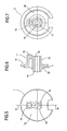
- the hub 7 comprises a first face 10 from which extends a cylindrical protrusion 11 and a second face 12 from which protrudes an element 13 substantially in the shape of a parallelepiped.
- the hub 7 has a through hole 14 that passes through a part of the protruding element 13 and cylindrical protrusion 11: the hole 14 defines a passage through the hub 7 into which the bolt 8 is inserted.
- a cylindrical protuberance 15 for fixing the hub 7 to one of the lateral arms 3 of the fork 2 by inserting the protuberance 15 into a matching hole made in the arm 3 of the fork 2, as shown in Figures 2 and 4 .
- the hub 7 is thus fixed relative to the fork 2 during trolley movement.
- the main wheel 5 comprises an internal disc 16 keyed to a ball bearing 17, the cylindrical protrusion 11 of the hub 7 being inserted in the ball bearing 17 in such a way as to enable the main wheel 5 to revolve about a defined axis X relative to the hub 7 itself, which is fixed to the fork 2.
- the internal disc 16 of the main wheel 5 has an outside face 18 facing a lateral arm 3 of the trolley fork 2 and an inside face 19 facing the auxiliary wheel 6.
- the outside face 18 has a plate 20 to make it easier to fix the wheel 5 to the fork 2.
- the inside face 19 has a plurality of peripheral seats 21 whose purpose is described in detail below.
- the inside disc 16 of the main wheel 5 has attached to it a ring 23 made of rubbery material forming the tread of the main wheel 5.
- the auxiliary wheel 6 comprises a circular crown 24 which is made of a plastic material, such as polyurethane, and which, since it is designed to brake the main wheel 5, and hence the trolley, must be thin enough to sink into the longitudinal grooves 25 of standard width (6-7 millimetres) of a passenger conveyor 100.
- a plastic material such as polyurethane
- the circular crown 24 is mounted on a central disc 26 with an interposed ball crown ring 27 so that the auxiliary wheel 6 can freely rotate relative to the central disc 26 itself.
- the central disc 26 has an inside face 28 facing the main wheel 5 and an outside face 29 facing a lateral arm 3 of the fork 2.
- the central disc 26 has a substantially rectangular slot 30 designed to receive the parallelepiped-shaped.element 13 protruding from the hub 7.
- the central disc 26 is therefore free to move vertically relative to the hub 7 and main wheel 5 thanks to the presence of the slot 30.
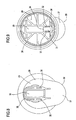
- the central disc 26 is movable between a raised position, illustrated in Figure 2 , and a lowered operating position, illustrated in Figure 10 , through a plurality of intermediate positions, one of which is illustrated in Figure 11 .
- the central disc 26 comprises, on the inside face 28, under the slot 30, a seat 31 defined by two lateral walls 32, 33 and a front wall 34, designed to contain a spring 35.
- the spring 35 is located inside the seat 31 under and opposing the parallelepiped shaped element 13 protruding from the hub 7 and inserted in the slot 30.
- the spring 35 exerts a downward force on the central disc 26 and tends to move it to the lowered wheel locked position.
- the spring 35 constitutes elastic means acting on the auxiliary wheel 6 in such a way as to urge the auxiliary wheel 6 into the lowered, locked operating position.
- the inside face 28 of the central disc 26 comprises a pawl 36 extending from the inside face 28 towards the inside face 19 of the internal disc 16 of the main wheel 5 and designed to engage one of the seats 21 of the inside face 19 of the internal disc 16 of the main wheel 5.
- the central disc 26 is free to move vertically relative to the main wheel 5 between a first, non-operating raised position, through a plurality of non-operating, intermediate positions, where the pawl 36 does not engage any of the seats 21, and the above mentioned lowered, operating position in which the pawl 36 engages one of the seats 21, as shown in Figure 10 .
- the main wheel 5 is free to rotate relative to the central disc 26 of the auxiliary wheel 6, the central disc 26 being, on the other hand, fixed to the fork 2.
- the pawl 36 of the central disc 26 of the auxiliary wheel 6 is engaged with one of the seats 21 on the inside face 19 of the main wheel 5, the main wheel 5 thus being locked relative to the central disc 26 of the auxiliary wheel 6.
- the only degree of freedom of the disc 26, therefore, is vertical translational movement relative to the hub 7.
- the outside face 29 of the central disc 26 of the auxiliary wheel 6 comprises a protrusion 37 for stopping the vertical translational movement of the disc 26 and auxiliary wheel 6.
- the protrusion 37 extends in a plane P1 parallel to the auxiliary wheel 6 and is located at a predetermined distance D1 from the auxiliary wheel 6 itself.
- the protrusion is raised relative to the auxiliary wheel 6, with reference to the plane defined by the floor so that, when the auxiliary wheel 6 is in contact with the floor 101, the protrusion 37 is, instead, raised off the floor.
- the protrusion 37 is made of a plastic material.
- the protrusion 37 is designed to keep the auxiliary wheel 6 in one of the raised, non-operating positions until the trolley is pushed onto the inclined conveyor 100.
- the protrusion 37 enables the central disc 26 to move into the lowered operating position where the main wheel 5 is locked in the longitudinal grooves 25.
- the outside face 29 of the central disc 26 comprises a plurality of channels 38 made at the rectangular slot 30, designed to prevent dirt from accumulating at the slot 30 itself.
- the protrusion 37 constitutes means 39 for controlling the auxiliary wheel 6 designed to keep the auxiliary wheel 6 in one of the raised, non-operating positions until the trolley is off the conveyor 100.
- control means 39 enable the auxiliary wheel 6 to move into the lowered operating position inside one of the grooves 25.
- the floor 101 exerts on the auxiliary wheel 6 an upwardly directed force in reaction to the weight of the trolley itself.
- the reaction force exerted by the floor 101 is sufficient to overcome the downwardly directed pushing force exerted by the spring 35 and tending to keep the auxiliary wheel 6 in the lowered operating position where the auxiliary wheel 6 itself is locked.
- the auxiliary wheel 6 remains in the first, non-operating raised position in contact with the floor 101 together with the main wheel 5.
- the pawl 36 of the central disc 26 of the auxiliary wheel 6 is not engaged with any of the seats 21 on the internal disc 16 of the main wheel 5 and the main wheel 5 is thus free to revolve together with the crown ring 24 of the auxiliary wheel 6, thus allowing the trolley to move freely.
- the protrusion 37 connected to the central disc 26 is not, however, in contact with the floor 101 since it is, advantageously, raised relative to the crown ring 24.
- the crown ring 24 of the auxiliary wheel 6 sinks into the groove 25 and the pawl 36 of the central disc 26 engages one of the seats 21 on the internal disc 16 of the main wheel 5.
- the distance D1 is calculated in such a way that when the crown ring 24 of the auxiliary wheel 6 sinks into one groove 25, the protrusion 37 sinks into an adjacent groove.
- the distance D1 is a whole multiple of the distance between two adjacent grooves 25.
- the central disc 26 is fixed to the lateral arms 3 of the trolley fork 2 by means of the bolt 8 and cylindrical protuberance 15 of the parallelepiped shaped element 13 on the hub 7.
- control means 39 comprise, instead of the protrusion 37, a second crown ring 41 parallel to the first crown ring 24, located at a distance D2 from the latter and mounted, together with the first crown ring 24, on the central disc 26 of the auxiliary wheel, with an interposed ball crown ring 27.
- the distance D2 is such that when the auxiliary wheel 6 is in the lowered position, inside one of the grooves 25 of the conveyor 100, the second crown ring 41 is inside another groove 25 of the conveyor 100.
- control means comprise a supporting wheel rotatably mounted on the central disc of the auxiliary wheel.
- the supporting wheel is located at a predetermined distance from the auxiliary wheel.
- This distance is such that when the auxiliary wheel is in the lowered position, inside one of the grooves of the conveyor, the supporting wheel is inside another groove of the conveyor.
Landscapes
- Engineering & Computer Science (AREA)
- Mechanical Engineering (AREA)
- Handcart (AREA)
- Braking Arrangements (AREA)
Claims (12)
- Une roulette autofreinée applicable sur les bras latéraux (3) de fourches (2) de chariots de transport, en particulier de chariots à provisions, comprenant :- une roue principale (5) de roulement qui tourne autour d'un axe (X) défini ; et- une roue auxiliaire (6) essentiellement accolée à la roue principale (5) et destinée à être insérée dans des rainures longitudinales (25) de tapis roulants ; la roue auxiliaire (6) étant mobile verticalement, dans un plan (P) perpendiculaire à l'axe (X) de rotation de la roue principale (5), entre une première position non opérationnelle soulevée en passant par une pluralité de positions non opérationnelles intermédiaires dans lesquelles la roue auxiliaire (6) permet la rotation de la roue principale (5), et une position opérationnelle abaissée dans laquelle la roue auxiliaire (6) est insérée dans une des rainures longitudinales (25) et empêche la rotation de la roue principale (5) ; la roulette étant caractérisée en ce qu'elle comprend des moyens (39) servant à commander la roue auxiliaire (6) et destinés à maintenir ladite roue auxiliaire (6) au moins dans une des positions non opérationnelles intermédiaires jusqu'à ce que le chariot soit en dehors du tapis (100) ; lesdits moyens de commande (39) permettant à la roue auxiliaire (6) de venir se placer dans la position opérationnelle abaissée, à l'intérieur de l'une des rainures (25), quand le chariot est placé sur le tapis (100).
- La roulette selon la revendication 1, caractérisée en ce que la roue auxiliaire (6) comprend une couronne circulaire (24) montée de façon rotative sur un disque central (26) destiné à venir en prise avec la roue principale (5) et ayant une face intérieure (28) orientée vers la roue principale (5) et une face extérieure (29) orientée vers un bras (3) de la fourche (2) du chariot, ledit disque (26) étant mobile verticalement entre une pluralité de positions non opérationnelles soulevées, dans lesquelles il permet la rotation de la roue principale (5), et une position opérationnelle abaissée dans laquelle il vient en prise avec la roue principale (5) et empêche la rotation de la roue principale (5), et en ce que les moyens de commande (39) comprennent un appendice (37) destiné à arrêter le mouvement de translation vertical du disque (26) et de la couronne circulaire (24), ledit appendice (37) étant fixé au disque central (26) et étant situé à une distance (D1) prédéfinie de la couronne circulaire (24), la distance (D1) étant telle que, lorsque la roue auxiliaire (6) est dans la position abaissée à l'intérieur de l'une des rainures (25) du tapis (100), l'appendice (37) est à l'intérieur d'une autre rainure (25) du tapis (100).
- La roulette selon la revendication 2, caractérisée en ce que l'appendice (37) est essentiellement parallèle à la couronne circulaire (24).
- La roulette selon la revendication 1, caractérisée en ce que la roue auxiliaire (6) comprend une couronne circulaire (24) montée de façon rotative sur un disque central (26) destiné à venir en prise avec la roue principale (5) et ayant une face intérieure (28) orientée vers la roue principale (5) et une face extérieure (29) orientée vers un bras (3) de la fourche (2) du chariot, ledit disque (26) étant mobile verticalement entre une pluralité de positions non opérationnelles soulevées, dans lesquelles il permet la rotation de la roue principale (5), et une position opérationnelle abaissée dans laquelle il vient en prise avec la roue principale (5) et empêche la rotation de la roue principale (5), et en ce que les moyens de commande (39) comprennent une deuxième couronne circulaire (41) solidaire de la première couronne circulaire (24) et montée de façon rotative par rapport au disque central (26), ladite deuxième couronne circulaire (41) étant située à une distance (D2) prédéfinie de la première couronne circulaire (24) de manière à ce que, lorsque la couronne circulaire (24) auxiliaire est dans la position opérationnelle abaissée à l'intérieur de l'une des rainures (25) du tapis (100), la deuxième couronne circulaire (41) soit à l'intérieur d'une autre rainure (25) du tapis (100).
- La roulette selon la revendication 1, caractérisée en ce que la roue auxiliaire (6) est montée de façon rotative sur un disque central (26) destiné à venir en prise avec la roue principale (5) et ayant une face intérieure (28) orientée vers la roue principale (5) et une face extérieure (29) orientée vers un bras (3) de la fourche (2) du chariot, ledit disque (26) étant mobile verticalement entre une pluralité de positions non opérationnelles soulevées, dans lesquelles il permet la rotation de la roue principale (5), et une position opérationnelle abaissée dans laquelle il empêche la rotation de la roue principale (5), et en ce que les moyens de commande (39) comprennent une roue d'appui montée de façon rotative sur le disque central, ladite roue d'appui étant parallèle à la roue auxiliaire et étant située à une distance prédéfinie de cette même roue auxiliaire (6), ladite distance étant telle que, lorsque la roue auxiliaire (6) est dans la position abaissée à l'intérieur de l'une des rainures (25) du tapis (100), ladite roue d'appui est à l'intérieur d'une autre rainure (25) du tapis (100).
- La roulette selon l'une quelconque des revendications précédentes de 2 à 5, caractérisée en ce que le disque central (26) comprend un cliquet (36) saillant de la face intérieure (28) et destiné à venir en prise avec des logements (21) correspondants réalisés sur la roue principale (5) lorsque le disque (26) et la roue auxiliaire (6) sont dans la position opérationnelle abaissée, de manière à ce que la roue principale (5) soit bloquée par rapport audit disque (26).
- La roulette selon la revendication 6, caractérisée en ce qu'elle comprend un moyeu (7) reliant la roue principale (5) aux bras latéraux (3) de la fourche (2), la roue (5) pouvant librement tourner par rapport au moyeu (7), ledit moyeu (7) comprenant un élément saillant (13), essentiellement rectangulaire, qui peut être associé au disque central (26) de la roue auxiliaire (6).
- La roulette selon la revendication 7, caractérisée en ce que l'élément (13) saillant du moyeu (7) comprend une partie qui est destinée à être fixée à la fourche (2).
- La roulette selon la revendication 8, caractérisée en ce que le disque central (26) comprend une fente (30) essentiellement rectangulaire dans laquelle est inséré l'élément saillant (13) du moyeu (7), ladite fente (30) étant destinée à faire coulisser verticalement le disque (26) par rapport au moyeu (7) et à bloquer la rotation dudit disque (26) par rapport audit moyeu (7).
- La roulette selon la revendication 9, caractérisée en ce que le disque central (26) comprend un ressort (35) situé dans la fente (30), ledit ressort (35) exerçant une force sur l'élément saillant (13) du moyeu de manière à ce que le ressort (35) lui-même ait tendance à maintenir le disque (26) dans la deuxième position opérationnelle abaissée.
- La roulette selon la revendication 10, caractérisée en ce que la face intérieure (28) du disque central (26) comprend un logement (31) défini par deux parois latérales (32, 33) et une paroi avant (34), ledit logement (31) étant destiné à recevoir de façon stable le ressort (35).
- La roulette selon l'une quelconque des revendications précédentes de 2 à 9, caractérisée en ce que la face extérieure (29) du disque central (26) comprend une pluralité de canaux (38) réalisés au niveau de la fente rectangulaire (30) et destinés à empêcher la saleté de s'accumuler au niveau de la fente (30) elle-même.
Priority Applications (3)
| Application Number | Priority Date | Filing Date | Title |
|---|---|---|---|
| EP08425218A EP2106929B1 (fr) | 2008-04-03 | 2008-04-03 | Roulette autofreinée pour chariot de transport |
| AT08425218T ATE461058T1 (de) | 2008-04-03 | 2008-04-03 | Selbstbremsende rolle für transportwagen |
| DE602008000843T DE602008000843D1 (de) | 2008-04-03 | 2008-04-03 | Selbstbremsende Rolle für Transportwagen |
Applications Claiming Priority (1)
| Application Number | Priority Date | Filing Date | Title |
|---|---|---|---|
| EP08425218A EP2106929B1 (fr) | 2008-04-03 | 2008-04-03 | Roulette autofreinée pour chariot de transport |
Publications (2)
| Publication Number | Publication Date |
|---|---|
| EP2106929A1 EP2106929A1 (fr) | 2009-10-07 |
| EP2106929B1 true EP2106929B1 (fr) | 2010-03-17 |
Family
ID=39712536
Family Applications (1)
| Application Number | Title | Priority Date | Filing Date |
|---|---|---|---|
| EP08425218A Not-in-force EP2106929B1 (fr) | 2008-04-03 | 2008-04-03 | Roulette autofreinée pour chariot de transport |
Country Status (3)
| Country | Link |
|---|---|
| EP (1) | EP2106929B1 (fr) |
| AT (1) | ATE461058T1 (fr) |
| DE (1) | DE602008000843D1 (fr) |
Families Citing this family (1)
| Publication number | Priority date | Publication date | Assignee | Title |
|---|---|---|---|---|
| EP2399758B1 (fr) * | 2010-06-24 | 2013-01-16 | K. Hartwall Oy AB | Galet pivotant |
Family Cites Families (5)
| Publication number | Priority date | Publication date | Assignee | Title |
|---|---|---|---|---|
| DE2105547A1 (de) * | 1971-02-06 | 1972-08-10 | Tente Rollen GmbH & Co, 5678 Wermelskirchen Tente | Lenkrolle, insbesondere fur Ein kaufswagen in Selbstbedienungsladen |
| JPS57138401A (en) * | 1981-02-17 | 1982-08-26 | Naohisa Hashimoto | Castor |
| DE3841697A1 (de) * | 1988-12-10 | 1990-06-13 | Wanzl Metallwarenfabrik Kg | Fahrrolle zur befestigung an transportwagen, insbesondere an einkaufswagen |
| FR2707232B1 (fr) * | 1993-07-05 | 1995-09-15 | Caddie Atel Reunis | Roulette pour chariot susceptible d'être immobilisé sur un trottoir roulant. |
| DE19611902A1 (de) * | 1996-03-26 | 1997-10-02 | Rhombus Rollen Gmbh & Co | Lenkrolle für Transportgeräte, wie Einkaufswagen o. dgl. |
-
2008
- 2008-04-03 EP EP08425218A patent/EP2106929B1/fr not_active Not-in-force
- 2008-04-03 DE DE602008000843T patent/DE602008000843D1/de active Active
- 2008-04-03 AT AT08425218T patent/ATE461058T1/de not_active IP Right Cessation
Also Published As
| Publication number | Publication date |
|---|---|
| DE602008000843D1 (de) | 2010-04-29 |
| EP2106929A1 (fr) | 2009-10-07 |
| ATE461058T1 (de) | 2010-04-15 |
Similar Documents
| Publication | Publication Date | Title |
|---|---|---|
| US3608693A (en) | Rollers, particularly for shopping trolleys | |
| EP2813410B1 (fr) | Chariot à plateforme de déplacement d'objets lourds | |
| EP1750989B1 (fr) | Chariot a roue de guidage pivotante | |
| CA2589542A1 (fr) | Chariot a palettes | |
| KR20090079868A (ko) | 구름바퀴의 스토퍼장치 | |
| US6331009B1 (en) | Control wheel assembly for trolleys | |
| EP2106929B1 (fr) | Roulette autofreinée pour chariot de transport | |
| WO2008007050A1 (fr) | Procédé et appareil pour freiner une roue | |
| EP3782873B1 (fr) | Chariot de déplacement de marchandises lourdes | |
| CA2527077C (fr) | Chariots d'entreposage | |
| WO1995008449A1 (fr) | Roulettes | |
| WO1994010000A1 (fr) | Ensemble de roulette | |
| KR101434937B1 (ko) | 보조롤러부가 결합된 쇼핑 카트용 바퀴 | |
| KR200490642Y1 (ko) | 쇼핑카트의 이동바퀴용 마찰패드 | |
| EP4556347A1 (fr) | Dispositif de distribution d'article décoratif | |
| JPH0624299Y2 (ja) | 親子台車 | |
| WO1993001077A1 (fr) | Ameliorations relatives a des systemes de caddies reciproquement emboitables | |
| JPH0522487Y2 (fr) | ||
| EP0105144B1 (fr) | Dispositif d'immobilisation à cames pour roulettes orientables | |
| KR102664011B1 (ko) | 단차 극복 기능을 갖는 캐스터 장치 및 이를 포함하는 운반 수단 | |
| WO1985001259A1 (fr) | Chassis de chariot a roues | |
| CN223605390U (zh) | 一种腾空后自动复位的万向脚轮 | |
| AU706977B2 (en) | A wheel | |
| KR102855676B1 (ko) | 서브휠을 구비한 쇼핑카트 | |
| AU712834B2 (en) | A wheel and brake assembly |
Legal Events
| Date | Code | Title | Description |
|---|---|---|---|
| PUAI | Public reference made under article 153(3) epc to a published international application that has entered the european phase |
Free format text: ORIGINAL CODE: 0009012 |
|
| GRAP | Despatch of communication of intention to grant a patent |
Free format text: ORIGINAL CODE: EPIDOSNIGR1 |
|
| 17P | Request for examination filed |
Effective date: 20081024 |
|
| AK | Designated contracting states |
Kind code of ref document: A1 Designated state(s): AT BE BG CH CY CZ DE DK EE ES FI FR GB GR HR HU IE IS IT LI LT LU LV MC MT NL NO PL PT RO SE SI SK TR |
|
| AX | Request for extension of the european patent |
Extension state: AL BA MK RS |
|
| GRAS | Grant fee paid |
Free format text: ORIGINAL CODE: EPIDOSNIGR3 |
|
| GRAA | (expected) grant |
Free format text: ORIGINAL CODE: 0009210 |
|
| AK | Designated contracting states |
Kind code of ref document: B1 Designated state(s): AT BE BG CH CY CZ DE DK EE ES FI FR GB GR HR HU IE IS IT LI LT LU LV MC MT NL NO PL PT RO SE SI SK TR |
|
| REG | Reference to a national code |
Ref country code: GB Ref legal event code: FG4D |
|
| REG | Reference to a national code |
Ref country code: CH Ref legal event code: EP |
|
| REG | Reference to a national code |
Ref country code: IE Ref legal event code: FG4D |
|
| REF | Corresponds to: |
Ref document number: 602008000843 Country of ref document: DE Date of ref document: 20100429 Kind code of ref document: P |
|
| AKX | Designation fees paid |
Designated state(s): AT BE BG CH CY CZ DE DK EE ES FI FR GB GR HR HU IE IS IT LI LT LU LV MC MT NL NO PL PT RO SE SI SK TR |
|
| REG | Reference to a national code |
Ref country code: NL Ref legal event code: VDEP Effective date: 20100317 |
|
| PG25 | Lapsed in a contracting state [announced via postgrant information from national office to epo] |
Ref country code: NO Free format text: LAPSE BECAUSE OF FAILURE TO SUBMIT A TRANSLATION OF THE DESCRIPTION OR TO PAY THE FEE WITHIN THE PRESCRIBED TIME-LIMIT Effective date: 20100617 Ref country code: HR Free format text: LAPSE BECAUSE OF FAILURE TO SUBMIT A TRANSLATION OF THE DESCRIPTION OR TO PAY THE FEE WITHIN THE PRESCRIBED TIME-LIMIT Effective date: 20100317 Ref country code: LT Free format text: LAPSE BECAUSE OF FAILURE TO SUBMIT A TRANSLATION OF THE DESCRIPTION OR TO PAY THE FEE WITHIN THE PRESCRIBED TIME-LIMIT Effective date: 20100317 |
|
| LTIE | Lt: invalidation of european patent or patent extension |
Effective date: 20100317 |
|
| PG25 | Lapsed in a contracting state [announced via postgrant information from national office to epo] |
Ref country code: SI Free format text: LAPSE BECAUSE OF FAILURE TO SUBMIT A TRANSLATION OF THE DESCRIPTION OR TO PAY THE FEE WITHIN THE PRESCRIBED TIME-LIMIT Effective date: 20100317 Ref country code: PL Free format text: LAPSE BECAUSE OF FAILURE TO SUBMIT A TRANSLATION OF THE DESCRIPTION OR TO PAY THE FEE WITHIN THE PRESCRIBED TIME-LIMIT Effective date: 20100317 Ref country code: AT Free format text: LAPSE BECAUSE OF FAILURE TO SUBMIT A TRANSLATION OF THE DESCRIPTION OR TO PAY THE FEE WITHIN THE PRESCRIBED TIME-LIMIT Effective date: 20100317 Ref country code: FI Free format text: LAPSE BECAUSE OF FAILURE TO SUBMIT A TRANSLATION OF THE DESCRIPTION OR TO PAY THE FEE WITHIN THE PRESCRIBED TIME-LIMIT Effective date: 20100317 Ref country code: LV Free format text: LAPSE BECAUSE OF FAILURE TO SUBMIT A TRANSLATION OF THE DESCRIPTION OR TO PAY THE FEE WITHIN THE PRESCRIBED TIME-LIMIT Effective date: 20100317 |
|
| PG25 | Lapsed in a contracting state [announced via postgrant information from national office to epo] |
Ref country code: SE Free format text: LAPSE BECAUSE OF FAILURE TO SUBMIT A TRANSLATION OF THE DESCRIPTION OR TO PAY THE FEE WITHIN THE PRESCRIBED TIME-LIMIT Effective date: 20100317 Ref country code: RO Free format text: LAPSE BECAUSE OF FAILURE TO SUBMIT A TRANSLATION OF THE DESCRIPTION OR TO PAY THE FEE WITHIN THE PRESCRIBED TIME-LIMIT Effective date: 20100317 Ref country code: NL Free format text: LAPSE BECAUSE OF FAILURE TO SUBMIT A TRANSLATION OF THE DESCRIPTION OR TO PAY THE FEE WITHIN THE PRESCRIBED TIME-LIMIT Effective date: 20100317 Ref country code: GR Free format text: LAPSE BECAUSE OF FAILURE TO SUBMIT A TRANSLATION OF THE DESCRIPTION OR TO PAY THE FEE WITHIN THE PRESCRIBED TIME-LIMIT Effective date: 20100618 Ref country code: ES Free format text: LAPSE BECAUSE OF FAILURE TO SUBMIT A TRANSLATION OF THE DESCRIPTION OR TO PAY THE FEE WITHIN THE PRESCRIBED TIME-LIMIT Effective date: 20100628 Ref country code: EE Free format text: LAPSE BECAUSE OF FAILURE TO SUBMIT A TRANSLATION OF THE DESCRIPTION OR TO PAY THE FEE WITHIN THE PRESCRIBED TIME-LIMIT Effective date: 20100317 Ref country code: CY Free format text: LAPSE BECAUSE OF FAILURE TO SUBMIT A TRANSLATION OF THE DESCRIPTION OR TO PAY THE FEE WITHIN THE PRESCRIBED TIME-LIMIT Effective date: 20100317 Ref country code: BE Free format text: LAPSE BECAUSE OF FAILURE TO SUBMIT A TRANSLATION OF THE DESCRIPTION OR TO PAY THE FEE WITHIN THE PRESCRIBED TIME-LIMIT Effective date: 20100317 |
|
| PG25 | Lapsed in a contracting state [announced via postgrant information from national office to epo] |
Ref country code: CZ Free format text: LAPSE BECAUSE OF FAILURE TO SUBMIT A TRANSLATION OF THE DESCRIPTION OR TO PAY THE FEE WITHIN THE PRESCRIBED TIME-LIMIT Effective date: 20100317 Ref country code: SK Free format text: LAPSE BECAUSE OF FAILURE TO SUBMIT A TRANSLATION OF THE DESCRIPTION OR TO PAY THE FEE WITHIN THE PRESCRIBED TIME-LIMIT Effective date: 20100317 Ref country code: BG Free format text: LAPSE BECAUSE OF FAILURE TO SUBMIT A TRANSLATION OF THE DESCRIPTION OR TO PAY THE FEE WITHIN THE PRESCRIBED TIME-LIMIT Effective date: 20100617 Ref country code: MC Free format text: LAPSE BECAUSE OF NON-PAYMENT OF DUE FEES Effective date: 20100430 Ref country code: IS Free format text: LAPSE BECAUSE OF FAILURE TO SUBMIT A TRANSLATION OF THE DESCRIPTION OR TO PAY THE FEE WITHIN THE PRESCRIBED TIME-LIMIT Effective date: 20100717 |
|
| PLBE | No opposition filed within time limit |
Free format text: ORIGINAL CODE: 0009261 |
|
| STAA | Information on the status of an ep patent application or granted ep patent |
Free format text: STATUS: NO OPPOSITION FILED WITHIN TIME LIMIT |
|
| PG25 | Lapsed in a contracting state [announced via postgrant information from national office to epo] |
Ref country code: IE Free format text: LAPSE BECAUSE OF NON-PAYMENT OF DUE FEES Effective date: 20100403 Ref country code: DK Free format text: LAPSE BECAUSE OF FAILURE TO SUBMIT A TRANSLATION OF THE DESCRIPTION OR TO PAY THE FEE WITHIN THE PRESCRIBED TIME-LIMIT Effective date: 20100317 |
|
| 26N | No opposition filed |
Effective date: 20101220 |
|
| PG25 | Lapsed in a contracting state [announced via postgrant information from national office to epo] |
Ref country code: MT Free format text: LAPSE BECAUSE OF FAILURE TO SUBMIT A TRANSLATION OF THE DESCRIPTION OR TO PAY THE FEE WITHIN THE PRESCRIBED TIME-LIMIT Effective date: 20100317 |
|
| PG25 | Lapsed in a contracting state [announced via postgrant information from national office to epo] |
Ref country code: PT Free format text: LAPSE BECAUSE OF FAILURE TO SUBMIT A TRANSLATION OF THE DESCRIPTION OR TO PAY THE FEE WITHIN THE PRESCRIBED TIME-LIMIT Effective date: 20100817 Ref country code: LU Free format text: LAPSE BECAUSE OF NON-PAYMENT OF DUE FEES Effective date: 20100403 Ref country code: HU Free format text: LAPSE BECAUSE OF FAILURE TO SUBMIT A TRANSLATION OF THE DESCRIPTION OR TO PAY THE FEE WITHIN THE PRESCRIBED TIME-LIMIT Effective date: 20100918 |
|
| PG25 | Lapsed in a contracting state [announced via postgrant information from national office to epo] |
Ref country code: TR Free format text: LAPSE BECAUSE OF FAILURE TO SUBMIT A TRANSLATION OF THE DESCRIPTION OR TO PAY THE FEE WITHIN THE PRESCRIBED TIME-LIMIT Effective date: 20100317 |
|
| REG | Reference to a national code |
Ref country code: CH Ref legal event code: PL |
|
| GBPC | Gb: european patent ceased through non-payment of renewal fee |
Effective date: 20120403 |
|
| PG25 | Lapsed in a contracting state [announced via postgrant information from national office to epo] |
Ref country code: GB Free format text: LAPSE BECAUSE OF NON-PAYMENT OF DUE FEES Effective date: 20120403 Ref country code: LI Free format text: LAPSE BECAUSE OF NON-PAYMENT OF DUE FEES Effective date: 20120430 Ref country code: CH Free format text: LAPSE BECAUSE OF NON-PAYMENT OF DUE FEES Effective date: 20120430 |
|
| PGFP | Annual fee paid to national office [announced via postgrant information from national office to epo] |
Ref country code: IT Payment date: 20140423 Year of fee payment: 7 Ref country code: FR Payment date: 20140428 Year of fee payment: 7 Ref country code: DE Payment date: 20140627 Year of fee payment: 7 |
|
| REG | Reference to a national code |
Ref country code: DE Ref legal event code: R119 Ref document number: 602008000843 Country of ref document: DE |
|
| PG25 | Lapsed in a contracting state [announced via postgrant information from national office to epo] |
Ref country code: IT Free format text: LAPSE BECAUSE OF NON-PAYMENT OF DUE FEES Effective date: 20150403 Ref country code: DE Free format text: LAPSE BECAUSE OF NON-PAYMENT OF DUE FEES Effective date: 20151103 |
|
| REG | Reference to a national code |
Ref country code: FR Ref legal event code: ST Effective date: 20151231 |
|
| PG25 | Lapsed in a contracting state [announced via postgrant information from national office to epo] |
Ref country code: FR Free format text: LAPSE BECAUSE OF NON-PAYMENT OF DUE FEES Effective date: 20150430 |