EP2106947A1 - Agencement de toit pour véhicules utilitaires - Google Patents
Agencement de toit pour véhicules utilitaires Download PDFInfo
- Publication number
- EP2106947A1 EP2106947A1 EP09156256A EP09156256A EP2106947A1 EP 2106947 A1 EP2106947 A1 EP 2106947A1 EP 09156256 A EP09156256 A EP 09156256A EP 09156256 A EP09156256 A EP 09156256A EP 2106947 A1 EP2106947 A1 EP 2106947A1
- Authority
- EP
- European Patent Office
- Prior art keywords
- joint
- scissors
- arrangement according
- scissor
- assembly
- Prior art date
- Legal status (The legal status is an assumption and is not a legal conclusion. Google has not performed a legal analysis and makes no representation as to the accuracy of the status listed.)
- Withdrawn
Links
Images


Classifications
-
- B—PERFORMING OPERATIONS; TRANSPORTING
- B60—VEHICLES IN GENERAL
- B60J—WINDOWS, WINDSCREENS, NON-FIXED ROOFS, DOORS, OR SIMILAR DEVICES FOR VEHICLES; REMOVABLE EXTERNAL PROTECTIVE COVERINGS SPECIALLY ADAPTED FOR VEHICLES
- B60J7/00—Non-fixed roofs; Roofs with movable panels, e.g. rotary sunroofs
- B60J7/02—Non-fixed roofs; Roofs with movable panels, e.g. rotary sunroofs of sliding type, e.g. comprising guide shoes
- B60J7/06—Non-fixed roofs; Roofs with movable panels, e.g. rotary sunroofs of sliding type, e.g. comprising guide shoes with non-rigid element or elements
- B60J7/061—Non-fixed roofs; Roofs with movable panels, e.g. rotary sunroofs of sliding type, e.g. comprising guide shoes with non-rigid element or elements sliding and folding
- B60J7/064—Non-fixed roofs; Roofs with movable panels, e.g. rotary sunroofs of sliding type, e.g. comprising guide shoes with non-rigid element or elements sliding and folding using folding arms sliding in longitudinal tracks for supporting the soft roof
- B60J7/065—Non-fixed roofs; Roofs with movable panels, e.g. rotary sunroofs of sliding type, e.g. comprising guide shoes with non-rigid element or elements sliding and folding using folding arms sliding in longitudinal tracks for supporting the soft roof for utility vehicles
Definitions
- the invention relates to a hood arrangement for commercial vehicles.
- top arrangements are common, in which cargo space a plurality of carriage assemblies in longitudinal guides of particular laterally spaced roof longitudinal beams are guided relative to each other. Between adjacent carriage assemblies, each pair of clipper assemblies are pivotally coupled to the carriage assemblies which are displaceable by relative movement of adjacent carriage assemblies between an extended position at maximum distance and an erect position with a minimum spacing of adjacent carriage assemblies. In the extended position of the jaw shears arrangements extends a flexible roof tarpaulin, which is supported by the jaw scissor assemblies and the carriage assemblies with the cargo space transversely to the direction spanning transverse brackets, essentially flat.
- the clamshell assemblies typically each include a pair of scissor brackets which are interconnected by first link assemblies to the carriage assemblies and by second link assemblies in a scissor linkage.
- Such top arrangements are known for example from the DE2436794A1 or the DE3137437C2 ,
- the DE69702305T2 and the DE29815722U1 show top arrangements in which continuous between successive carriage assemblies Plastic hinges with film hinges take over the function of the clipper assemblies.
- the EP1122108A2 shows bow shears assemblies in which a flat sheet metal body is displaceable relative to a first of two wire brackets and forms the scissors joint for the second wire bow.
- the sheet metal body is pulled in the extended position of the ironing shear assembly maximum away from the first wire hanger and is pushed further when pushing together adjacent carriage assemblies on the first bracket.
- the height of the shears is thereby reduced, whereby a clamping load of the tarpaulin is to be reduced.
- this is achieved in that a scissors joint connecting the wire legs of the scissor clamps in the scissors joint body consists of soft elastic variable-length material.
- the scissor brackets are mounted in such a manner that the ends of the wire hanger are bent horizontally as a bearing pin and eino in bearing recesses of two mounted on top of the carriage brackets bearing plates.
- the EP778169B1 shows a tarpaulin, in which swivel bracket are designed as flat strips, which form at their ends by bent extensions hinges, which are approximately centrally to the width of the strips and are short against the last width.
- An articulated connection to the cross-bow assemblies via bearing journals, which are held in one piece from the carriage consoles calipers.
- a bearing journal of a liftable transverse bow forms a common joint axis for the eyes of the two scissor clips to be connected to one another.
- the present invention has for its object to provide a top assembly for commercial vehicles, which in particular has advantageous bow thruster arrangements.
- the swivel body or the scissors joint body are preferably designed as plastic injection molded parts.
- the mutually facing joint stubs are preferably connected via axially intermeshing and radially locking Zentrierstruktukren at their facing ends, wherein such centering structures may preferably be formed by a running over at least the major part of the cumulative length of the cooperating joint stubborn bolts.
- Such a bolt can be poured in the embodiment of the injection-molded part in a formed on this joint stub when executing the swivel joint body or scissors joint body as plastic injection molded parts.
- the joint bushings are formed on the scissor bracket for the connection in the temple hinge assembly same as for the connection in the scissors hinge assembly.
- the joint sockets in the temple joint bodies on the one hand and the scissors joint bodies on the other side are dimensioned the same, so that it is not necessary to differentiate between differently configured or arranged joint sockets for the temple joint arrangement or the scissors joint arrangement during assembly of the scissors temple.
- a uniform shape can be used for both scissor brackets for the two scissor brackets of a clipper arrangement.
- bracket joint body used in pairs in a temple hinge assembly are identical within a pair, so that only one version of the articulated joint bodies is needed.
- the scissors joint bodies used in pairs in the scissors joint arrangements are advantageously also within a pair of scissors joint bodies built the same, so that even a design of scissors joint bodies is needed.
- both the swivel joint body and the scissors joint body each contain two joint sockets for the formation of two transverse to the axis direction spaced hinge axes in the respective joint assemblies and advantageously form a separate linkage for each bracket.
- the scissor bracket is advantageously about a perpendicular to the plane of its two pivot axes symmetry axis 180 ° rotationally symmetrical and can be mounted without distinction of the joint bushings in two equivalent installation positions, which greatly simplifies the assembly process.
- the swivel joint body can advantageously be fastened to the transverse bow arrangements, in particular to a middle section bridging a loading space between two runner sections.
- centering structures are advantageously formed between the swivel joint body and the transverse band arrangement, it being possible in particular for holes to be prepared in the transverse band arrangement in which centering elements of the swivel joint body engage, if these are fastened to the transverse band arrangement.
- the attachment is advantageously carried out without tools, in particular, a latching of a transversely to the mounting direction extending extension of the hanger body behind an edge of the transom assembly can be provided.
- the given in the pivot joint assembly first pivot axis is advantageously lower than the top of the crossbar assembly, in particular its central part, on which the tarpaulin rests in the stretched state.
- the first pivot axis or the first two pivot axes of the two hinge joint axes a pair of articulated bodies advantageously lie on opposite sides of the crossbar assembly adjacent thereto.
- the pairs of scissor-body bodies are advantageously positively connected to each other in the axial direction, for which in a preferred embodiment, the two scissors joint body complementary locking connections, for example in the form of latching hooks and corresponding grooves, which in the axial direction together engage in the assembly of the two scissors joint body and connect the two scissors joint body positively.
- the scissors joint body in their pairwise use two scissor hinge axes spaced transversely to the axial direction and each associated with one of the two scissor brackets.
- the scissors joint body advantageously contain a scissors joint with the joint bushings in the joint arrangements overlapping, on both sides protruding from a central part of the scissors joint body cover plate, which forms with its upper side a support surface for the flexible roof tarpaulin.
- the ironing joint body and / or the scissor joint body limit stops for the movement of the ironing shear assembly in the extended position, so that in the stretched position advantageously always a slight advance angling of the two connected scissor arms in the scissor joint assembly is given up.
- the hanger body first mating surfaces on which rest in the extended state of the hanger assembly first abutment surfaces of the scissor clamp.
- the scissors articulated body have second mating surfaces, abut against which second abutment surfaces of the scissor clamp in the extended position of the jaw scissor assembly.
- the second mating surfaces can be given in particular by the underside of a cover plate of the scissors joint body.
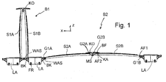
- Fig. 1 shows a side view of the essential mechanical components of a folding top assembly.
- a plurality of carriage assemblies LA are displaceable relative to one another and relative to the longitudinal guides along roof rails of a vehicle loading space which are not marked with longitudinal guides, in particular laterally spaced, in the x-direction.
- a tarpaulin is also not shown.
- a first pruning shears arrangement B1 with scissor-type stirrups S1A and S1B is shown in a fully erected position in which the longitudinal spacing of the trolley assemblies carrying trolleys is minimal, whereas the second pruning shears arrangement B2 with scissor-type stirrups S2A and S2B is in a second end position in which the pruning shears occupy a maximum stretched position and the distance of the trolley brackets S2A, S2B carrying trolley assemblies in the longitudinal direction is maximum, is drawn.
- the trolley assemblies and stirrup assemblies are typically displaced in the front roof area of a vehicle load compartment and release most of the roof opening for loading and unloading operations.
- the tarpaulin is folded up and lies between adjacent stirrup shears arrangements and on the upwardly facing surfaces of the scissors articulated body KO.
- the bow shears arrangements are located in the manner of the shearing device B2 in its extended position and the flexible roof tarpaulin is on the carriage assemblies LA and typically transverse to the longitudinal direction of the cargo space spanning transverse strap assemblies and on the upwardly facing surfaces of the scissor clamps S2A, S2B and the scissors articulated body KO.
- the scissor brackets S2A, S2B are pivotable about first pivot axes G1A, G1 B pivotably articulated to BK articulated bodies, which are attached to the carriage assemblies or such transversely connecting transverse strap assemblies. Facing away from the articulated joint bodies BK, the scissor brackets are pivotally connected about second pivot axes G2A, G2B in scissor joint arrangements with the scissors articulated bodies KO.
- the second pivot axes G2A, G2B should lie in the extended position above the plane formed by the first pivot axes G1A, G1B by a small amount.
- the scissor brackets S2A, S2B rest with first abutment surfaces AF1 on first opposing surfaces WHAT of the articulated joint body BK and second abutment surfaces AF2 on second opposing surfaces KA of the scissors articulated bodies KO and support the scissor arms in the extended position.
- Fig. 2 shows a preferred example of a scissor bracket, which in the example outlined advantageously consists of a one-piece formed sheet metal part.
- This sheet metal part has a large main surface HF, which is designed in the sketched advantageous example substantially rectangular with longitudinal edges LK1, LK2 and transverse edges QK1, QK2.
- Of the main surface preferably extend integrally sheet metal sections beyond the transverse edges and there are first joint sleeves G11, G12 and second joint sleeves G21, G22 reshaped.
- the deformed sheet metal sections are advantageously returned below the surface of the main surface HF.
- the sheet metal part of a relatively thin sheet preferably be folded with a sheet thickness of less than 1 mm, in particular less than 0.5 mm, wherein portions are provided with a plurality of sheet metal layers lying flat against each other, which in particular in the main surface at the longitudinal edges LK1 , LK2 can lie.
- the plurality of sheet metal layers may advantageously be connected in the surface, in particular by positive connection via clinch connections CB.
- the threaded bushings are then advantageously formed by sheet metal sections with at least two sheet metal layers, which lead, when returned under the main surface to a portion with four metal layers, which may be connected via clinch connections CG.
- the side edges of the main surface may be bent away therefrom and form side strips SS and / or raised or recessed structures may be provided in the main surface, for example in the form of beads RH and RT, respectively.
- a sheet metal part can be provided with only one sheet metal layer, to reduce weight and individual sections on the type of so-called "tailored blanks" may have different sheet wall thicknesses or individual sections have surface recesses.
- the first joint bushes G11, G12 are aligned along a first pivot axis G1A.
- the two first joint bushes are spaced apart in the direction of the pivot axis G1A and arranged in the direction of the pivot axis G1A close to the respective longitudinal edges LK1, LK2 of the main surface.
- the mutual distance between the two first joint bushes G11, G12 is advantageously greater than the length of the individual joint bushes G11, G12 in the direction of the pivot axis G1A.
- the length of the individual joint bushings is advantageously at least 15%, in particular at least 20% of the width of the main surface in the direction of the pivot axis G1A.
- the scissor-type clip can be installed equivalently in two structural positions, which differ by a rotation of the scissor-type clip about a center of rotation normal to the main surface of rotation of 180 °.
- a surface center normal forms a twofold rotational symmetry axis for the clip.
- the scissors bow can also be formed substantially mirror-symmetrical.
- Fig. 3 shows an advantageous embodiment of swashplate bodies which cooperate with the first joint bushes of a scissor bracket to form strap assemblies and are each used in pairs.
- the bracket joint body BK are advantageously constructed identically in the pairwise use, so that only one design of such a hanger body must be kept and also the assembly is simplified, because no differentiation between different U-joint bodies is required.
- Fig. 3 shows such a bracket joint body in a view obliquely from below (A) and a view obliquely from above (B).
- the bow shearing body BK has one of the respective cross bow assembly on which the bow shears body is attached, adapted basic shape, which in the present case for a rectangular outline of the cross section of a Transom bracket assembly comprising a middle plate BM forming upper plate with side plates BS and at the lower end projecting portions BH.
- the shape of the hanger body BK is particularly suitable that under bending the outlined bracket shape of the bracket joint body, preferably Toolless, is fitted from above the crossbar assembly and engage under the outlined sections BH lower edges of the crossbar assembly and return the bracket joint body securely on the crossbar assembly hold.
- centering elements WS can advantageously be provided, which engage in corresponding bores in the upper side of the transverse bow arrangement.
- additional locking elements WR can engage in holes on the underside of the crossbar assembly.
- TKB are provided, which are executed in a preferred embodiment of the hanger body BK as a plastic injection molded part in one piece with the basic shape.
- Carrier body TKA, TKB carry pointing in the y direction bracket joint WA or WB, which run in the mounted state along two first pivot axes G1A, G1B.
- a first joint WA on the first carrier body TKA contains a bolt BW, which projects beyond the end of the first joint stub WA facing away from the carrier body TKA.
- the bolt BW is advantageously embedded in the production of the hanger body as an injection molded part during the injection process in the first joint WA.
- the second joint socket WB has an end remote from the carrier body TKB Recess HU, which is matched to the protruding part of a bolt BW in the dimension and orientation.
- the bolts BW advantageously extend over the at least predominant length of the joint axes formed by the joint stubs WA, WB, preferably over their entire length.
- bracket joint body hold the joined position typically only by frictional connection on the bolt BW for further assembly process.
- the bracket joint body BK are attached to the pairwise assembly on the crossbar arrangements, for example, plugged in the manner described and are then held on the attachment to the crossbar assemblies, such as the centering WS in a defined position, so that the resulting paired assembly temple assemblies no longer loose can.
- TKB On the support bodies TKA, TKB advantageously first mating surfaces WAS are formed, which act together with the first abutment surfaces of the scissor clamps in the extended state of the stirrup shears arrangements and limit their pivoting downwards.
- Fig. 4 shows an advantageous embodiment of a scissors joint body in two different oblique views.
- the scissors joint body is advantageously made as a one-piece plastic injection-molded part and has a shape which allows a pairwise connection of two identical scissors joint body in a scissor hinge assembly.
- the scissors joint body contains two support bodies GTA, GTB, to which the joint socket GSA or GSB fastened, in particular molded.
- a first joint stub GSA in turn contains a bolt BO, which projects beyond the end of the joint stub GSA facing away from the carrier body GTA.
- a second joint socket GSB in turn contains a recess HU, which is tuned to the protruding end of the bolt BE in the dimension and orientation.
- Two identically constructed scissors joint body of the type outlined can be in relative to each other by 180 ° twisted position, including second joint bushes of the scissor clamps together to form a joint arrangement in which in turn joint socket of the two joined scissors joint body in the direction of second pivot axes G2A, G2B complement and the Separating points between mutually aligned and complementary joint stubs are bridged by the bolt BO.
- the threaded sockets GSA, GSB are inserted from opposite sides in the axial direction in threaded bushings of the clip.
- any known connection means can be provided.
- Particularly advantageous is the formation of locking structures on the facing in the assembled state sides of the scissors joint body, wherein such locking structures are complementary to each other and, for example, latching projections R1 and grooves N1, latching projections R2 and Contain grooves N2, which engage elastically yielding when joining two scissors joint body and ensure a secure axial connection of the jointed scissors joint body.
- Fig. 5 shows a view of an associated with two such Scherengelenkan extracten Scherenbügelpases in an oblique view from above.
- the upwardly facing surfaces FK of the paired scissors joint body complement each to a continuous surface.
- Fig. 5B shows the arrangement after Fig. 5A in oblique view from below with a view of the scissors joint arrangements with the second threaded bushes G21, G22.
- the scissors articulated body advantageously from a central part MS laterally facing arms BF of the cover plate, abut the underside KA on reaching the extended position second stop surfaces AF2 of the scissor clamps and are supported on these second mating surfaces KA.
- the latching connections are advantageously in the region of the middle part, so that elastic deformations of the protruding arms BF do not act on the latching structures when the scissors hinge arrangement is loaded in the extended position substantially.
Landscapes
- Engineering & Computer Science (AREA)
- Mechanical Engineering (AREA)
- Mutual Connection Of Rods And Tubes (AREA)
Applications Claiming Priority (1)
| Application Number | Priority Date | Filing Date | Title |
|---|---|---|---|
| DE200810000899 DE102008000899A1 (de) | 2008-03-31 | 2008-03-31 | Verdeckanordnung für Nutzfahrzeuge |
Publications (1)
| Publication Number | Publication Date |
|---|---|
| EP2106947A1 true EP2106947A1 (fr) | 2009-10-07 |
Family
ID=40809884
Family Applications (1)
| Application Number | Title | Priority Date | Filing Date |
|---|---|---|---|
| EP09156256A Withdrawn EP2106947A1 (fr) | 2008-03-31 | 2009-03-26 | Agencement de toit pour véhicules utilitaires |
Country Status (2)
| Country | Link |
|---|---|
| EP (1) | EP2106947A1 (fr) |
| DE (1) | DE102008000899A1 (fr) |
Cited By (5)
| Publication number | Priority date | Publication date | Assignee | Title |
|---|---|---|---|---|
| WO2012010618A1 (fr) | 2010-07-23 | 2012-01-26 | Vbg Group Truck Equipment N.V. | Structure pour un toit coulissant, système de toit coulissant, camion avec un système de toit coulissant, semi-remorque à rideaux latéraux avec un système de toit coulissant |
| EP2397394A3 (fr) * | 2010-06-18 | 2013-06-12 | TSE Trailer-System-Engineering GmbH & Co. KG | Agencement de véhicule utilitaire doté d'un toit coulissant plat |
| WO2015128468A1 (fr) * | 2014-02-28 | 2015-09-03 | Boge Elastmetall Gmbh | Plaque pliante |
| WO2015197046A3 (fr) * | 2014-06-23 | 2016-05-19 | European Trailer Systems Gmbh | Structure à bâche |
| EP3943325A1 (fr) * | 2020-07-23 | 2022-01-26 | F. Hesterberg & Söhne GmbH & Co. KG | Bâche coulissante pour une ouverture de toit d'une zone de chargement de véhicule utilitaire |
Families Citing this family (2)
| Publication number | Priority date | Publication date | Assignee | Title |
|---|---|---|---|---|
| DE102014008949B4 (de) * | 2014-06-23 | 2020-12-31 | European Trailer Systems Gmbh | Planenaufbau |
| DE102015007951A1 (de) | 2014-06-23 | 2015-12-24 | European Trailer Systems Gmbh | Planenaufbau |
Citations (9)
| Publication number | Priority date | Publication date | Assignee | Title |
|---|---|---|---|---|
| DE2436794A1 (de) | 1974-07-31 | 1976-02-12 | Heinrich Schwemmle | Verschiebbares verdeck fuer fahrzeuge |
| DE3137437C2 (fr) | 1981-09-21 | 1987-08-06 | Ed. Scharwaechter Gmbh & Co Kg, 5630 Remscheid, De | |
| DE9012980U1 (de) | 1990-09-12 | 1990-12-06 | Ed. Scharwächter GmbH + Co. Fahrzeugtechnik, 8355 Hengersberg | Zusammenschiebbares Verdeck, insbesondere für Lkw und Anhänger |
| DE9200417U1 (de) | 1992-01-15 | 1992-04-02 | Ed. Scharwächter GmbH + Co. Fahrzeugtechnik, 8355 Hengersberg | Flachbauendes, zusammenschiebbares Verdeck für Fahrzeuge, Fahrzeugaufbauten oder Container u.dgl. |
| EP0778169A1 (fr) * | 1995-12-08 | 1997-06-11 | POMMIER & CIE | Dipositif pour le bâchage de véhicules poids lourd |
| DE29815722U1 (de) | 1998-09-01 | 2000-01-13 | Edscha LKW-Schiebeverdecke GmbH, 94491 Hengersberg | Faltbarer Planenaufbau für Fahrzeugaufbauten und Container |
| DE69702305T2 (de) | 1996-03-04 | 2001-01-11 | Etes N.V., Houthalen | Öffnungsvorrichtung für einen mit einer plane ausgerüsteten behälter |
| EP1122108A2 (fr) | 2000-02-02 | 2001-08-08 | Autocar S.p.A. | Dispositif pour le pliage d'une bâche de véhicule de transport |
| DE10056050A1 (de) | 2000-11-11 | 2002-06-13 | Trailer System Engineering Gmb | Faltverdeckanordnung |
-
2008
- 2008-03-31 DE DE200810000899 patent/DE102008000899A1/de not_active Withdrawn
-
2009
- 2009-03-26 EP EP09156256A patent/EP2106947A1/fr not_active Withdrawn
Patent Citations (10)
| Publication number | Priority date | Publication date | Assignee | Title |
|---|---|---|---|---|
| DE2436794A1 (de) | 1974-07-31 | 1976-02-12 | Heinrich Schwemmle | Verschiebbares verdeck fuer fahrzeuge |
| DE3137437C2 (fr) | 1981-09-21 | 1987-08-06 | Ed. Scharwaechter Gmbh & Co Kg, 5630 Remscheid, De | |
| DE9012980U1 (de) | 1990-09-12 | 1990-12-06 | Ed. Scharwächter GmbH + Co. Fahrzeugtechnik, 8355 Hengersberg | Zusammenschiebbares Verdeck, insbesondere für Lkw und Anhänger |
| DE9200417U1 (de) | 1992-01-15 | 1992-04-02 | Ed. Scharwächter GmbH + Co. Fahrzeugtechnik, 8355 Hengersberg | Flachbauendes, zusammenschiebbares Verdeck für Fahrzeuge, Fahrzeugaufbauten oder Container u.dgl. |
| EP0778169A1 (fr) * | 1995-12-08 | 1997-06-11 | POMMIER & CIE | Dipositif pour le bâchage de véhicules poids lourd |
| EP0778169B1 (fr) | 1995-12-08 | 2000-02-23 | POMMIER & CIE | Dipositif pour le bâchage de véhicules poids lourd |
| DE69702305T2 (de) | 1996-03-04 | 2001-01-11 | Etes N.V., Houthalen | Öffnungsvorrichtung für einen mit einer plane ausgerüsteten behälter |
| DE29815722U1 (de) | 1998-09-01 | 2000-01-13 | Edscha LKW-Schiebeverdecke GmbH, 94491 Hengersberg | Faltbarer Planenaufbau für Fahrzeugaufbauten und Container |
| EP1122108A2 (fr) | 2000-02-02 | 2001-08-08 | Autocar S.p.A. | Dispositif pour le pliage d'une bâche de véhicule de transport |
| DE10056050A1 (de) | 2000-11-11 | 2002-06-13 | Trailer System Engineering Gmb | Faltverdeckanordnung |
Cited By (12)
| Publication number | Priority date | Publication date | Assignee | Title |
|---|---|---|---|---|
| EP2397394A3 (fr) * | 2010-06-18 | 2013-06-12 | TSE Trailer-System-Engineering GmbH & Co. KG | Agencement de véhicule utilitaire doté d'un toit coulissant plat |
| WO2012010618A1 (fr) | 2010-07-23 | 2012-01-26 | Vbg Group Truck Equipment N.V. | Structure pour un toit coulissant, système de toit coulissant, camion avec un système de toit coulissant, semi-remorque à rideaux latéraux avec un système de toit coulissant |
| BE1019433A5 (nl) * | 2010-07-23 | 2012-07-03 | Vbg Group Truck Equipment N V | Constructie voor een schuifdak, schuifdaksysteem, vrachtwagen met schuifdaksysteem, schuifzeiltrailer met een schuifdaksysteem. |
| CN103068603A (zh) * | 2010-07-23 | 2013-04-24 | Vbg集团卡车装备有限公司 | 滑顶结构、滑顶系统、具有滑顶系统的卡车、具有滑顶系统的侧帘拖车 |
| DE202011110682U1 (de) | 2010-07-23 | 2015-07-14 | European Trailer Systems Gmbh | Struktur für ein Schiebedach, Schiebedachsystem, Lastfahrzeug mit Schiebedachsystem Curtainsider Anhänger mit einem Schiebedachsystem |
| WO2015128468A1 (fr) * | 2014-02-28 | 2015-09-03 | Boge Elastmetall Gmbh | Plaque pliante |
| WO2015197046A3 (fr) * | 2014-06-23 | 2016-05-19 | European Trailer Systems Gmbh | Structure à bâche |
| CN107690397A (zh) * | 2014-06-23 | 2018-02-13 | 欧洲拖车系统公司 | 防水罩结构 |
| US10131213B2 (en) | 2014-06-23 | 2018-11-20 | European Trailer Systems Gmbh | Tarpaulin structure |
| US10882384B2 (en) | 2014-06-23 | 2021-01-05 | European Trailer Systems Gmbh | Tarpaulin structure |
| EA038746B1 (ru) * | 2014-06-23 | 2021-10-13 | Юропиен Трейлер Системз Гмбх | Тентовая конструкция |
| EP3943325A1 (fr) * | 2020-07-23 | 2022-01-26 | F. Hesterberg & Söhne GmbH & Co. KG | Bâche coulissante pour une ouverture de toit d'une zone de chargement de véhicule utilitaire |
Also Published As
| Publication number | Publication date |
|---|---|
| DE102008000899A1 (de) | 2009-10-01 |
Similar Documents
| Publication | Publication Date | Title |
|---|---|---|
| EP2106947A1 (fr) | Agencement de toit pour véhicules utilitaires | |
| WO2011138012A2 (fr) | Structure porteuse en treillis | |
| WO2010046049A1 (fr) | Poutre en treillis | |
| WO2014108161A1 (fr) | Barres de toit pour véhicule automobile | |
| EP1884410A2 (fr) | Porte-charge | |
| EP1578631B1 (fr) | Cabriolet comportant un toit mobile | |
| EP2069582A1 (fr) | Ossature porteuse | |
| DE102017223240A1 (de) | Betonpumpen-Mastarm-Segment mit in Längsrichtung variabler Blechstärke und Verfahren zum Herstellen eines solchen Betonpumpe-Mastarm-Segments | |
| EP1319771B1 (fr) | Store, notamment store à bras articulés | |
| EP2599923A1 (fr) | Outil de travail avec une console | |
| EP2675743A1 (fr) | Structure porteuse en treillis | |
| CH644927A5 (de) | Mobile klappbuehne. | |
| EP3287305A1 (fr) | Structure articulee et passage comprenant une structure articulee | |
| EP1799913A1 (fr) | Pont a ciseaux modulaire et dispositif d'installation, procede pour installer des ponts a ciseaux modulaires | |
| DE2705979B2 (de) | Lastwagen mit in seiner Längsrichtung verschiebbarem Ladebodenabschnitt | |
| EP1379402B1 (fr) | Toit a lamelles | |
| DE102004045906B4 (de) | Gestell für ein verschiebbares, von einer Plane überspanntes Dach eines Nutzaufbaus | |
| DE102008000898A1 (de) | Verdeckanordnung für Nutzfahrzeuge | |
| EP3943325A1 (fr) | Bâche coulissante pour une ouverture de toit d'une zone de chargement de véhicule utilitaire | |
| EP3278664A1 (fr) | Rampe de pulvérisation pour un dispositif de protection des plantes | |
| EP1578630B1 (fr) | Vehicule de type cabriolet a toit mobile | |
| DE10320820B4 (de) | Schwenklagereinrichtung für ein verstellbares Bauteil sowie Verfahren zur Montage einer solchen Schwenklagereinrichtung | |
| DE2418478B2 (de) | Klapptisch | |
| WO2019105981A1 (fr) | Coude comportant une tôle de cloisonnement repliée | |
| DE9201745U1 (de) | Doppelgelenkscharnier für Flügeltüren |
Legal Events
| Date | Code | Title | Description |
|---|---|---|---|
| PUAI | Public reference made under article 153(3) epc to a published international application that has entered the european phase |
Free format text: ORIGINAL CODE: 0009012 |
|
| AK | Designated contracting states |
Kind code of ref document: A1 Designated state(s): AT BE BG CH CY CZ DE DK EE ES FI FR GB GR HR HU IE IS IT LI LT LU LV MC MK MT NL NO PL PT RO SE SI SK TR |
|
| AX | Request for extension of the european patent |
Extension state: AL BA RS |
|
| AKX | Designation fees paid | ||
| STAA | Information on the status of an ep patent application or granted ep patent |
Free format text: STATUS: THE APPLICATION IS DEEMED TO BE WITHDRAWN |
|
| 18D | Application deemed to be withdrawn |
Effective date: 20100408 |
|
| REG | Reference to a national code |
Ref country code: DE Ref legal event code: 8566 |