EP2106948A1 - Structure de logement pour un moteur-roue - Google Patents
Structure de logement pour un moteur-roue Download PDFInfo
- Publication number
- EP2106948A1 EP2106948A1 EP09166467A EP09166467A EP2106948A1 EP 2106948 A1 EP2106948 A1 EP 2106948A1 EP 09166467 A EP09166467 A EP 09166467A EP 09166467 A EP09166467 A EP 09166467A EP 2106948 A1 EP2106948 A1 EP 2106948A1
- Authority
- EP
- European Patent Office
- Prior art keywords
- housing
- motor
- divided
- wheel
- suspension system
- Prior art date
- Legal status (The legal status is an assumption and is not a legal conclusion. Google has not performed a legal analysis and makes no representation as to the accuracy of the status listed.)
- Granted
Links
Images


Classifications
-
- B—PERFORMING OPERATIONS; TRANSPORTING
- B60—VEHICLES IN GENERAL
- B60K—ARRANGEMENT OR MOUNTING OF PROPULSION UNITS OR OF TRANSMISSIONS IN VEHICLES; ARRANGEMENT OR MOUNTING OF PLURAL DIVERSE PRIME-MOVERS IN VEHICLES; AUXILIARY DRIVES FOR VEHICLES; INSTRUMENTATION OR DASHBOARDS FOR VEHICLES; ARRANGEMENTS IN CONNECTION WITH COOLING, AIR INTAKE, GAS EXHAUST OR FUEL SUPPLY OF PROPULSION UNITS IN VEHICLES
- B60K7/00—Disposition of motor in, or adjacent to, traction wheel
- B60K7/0007—Disposition of motor in, or adjacent to, traction wheel the motor being electric
-
- B—PERFORMING OPERATIONS; TRANSPORTING
- B60—VEHICLES IN GENERAL
- B60K—ARRANGEMENT OR MOUNTING OF PROPULSION UNITS OR OF TRANSMISSIONS IN VEHICLES; ARRANGEMENT OR MOUNTING OF PLURAL DIVERSE PRIME-MOVERS IN VEHICLES; AUXILIARY DRIVES FOR VEHICLES; INSTRUMENTATION OR DASHBOARDS FOR VEHICLES; ARRANGEMENTS IN CONNECTION WITH COOLING, AIR INTAKE, GAS EXHAUST OR FUEL SUPPLY OF PROPULSION UNITS IN VEHICLES
- B60K17/00—Arrangement or mounting of transmissions in vehicles
- B60K17/04—Arrangement or mounting of transmissions in vehicles characterised by arrangement, location or kind of gearing
- B60K17/043—Transmission unit disposed in on near the vehicle wheel, or between the differential gear unit and the wheel
-
- B—PERFORMING OPERATIONS; TRANSPORTING
- B60—VEHICLES IN GENERAL
- B60K—ARRANGEMENT OR MOUNTING OF PROPULSION UNITS OR OF TRANSMISSIONS IN VEHICLES; ARRANGEMENT OR MOUNTING OF PLURAL DIVERSE PRIME-MOVERS IN VEHICLES; AUXILIARY DRIVES FOR VEHICLES; INSTRUMENTATION OR DASHBOARDS FOR VEHICLES; ARRANGEMENTS IN CONNECTION WITH COOLING, AIR INTAKE, GAS EXHAUST OR FUEL SUPPLY OF PROPULSION UNITS IN VEHICLES
- B60K7/00—Disposition of motor in, or adjacent to, traction wheel
- B60K2007/0038—Disposition of motor in, or adjacent to, traction wheel the motor moving together with the wheel axle
-
- B—PERFORMING OPERATIONS; TRANSPORTING
- B60—VEHICLES IN GENERAL
- B60K—ARRANGEMENT OR MOUNTING OF PROPULSION UNITS OR OF TRANSMISSIONS IN VEHICLES; ARRANGEMENT OR MOUNTING OF PLURAL DIVERSE PRIME-MOVERS IN VEHICLES; AUXILIARY DRIVES FOR VEHICLES; INSTRUMENTATION OR DASHBOARDS FOR VEHICLES; ARRANGEMENTS IN CONNECTION WITH COOLING, AIR INTAKE, GAS EXHAUST OR FUEL SUPPLY OF PROPULSION UNITS IN VEHICLES
- B60K7/00—Disposition of motor in, or adjacent to, traction wheel
- B60K2007/0092—Disposition of motor in, or adjacent to, traction wheel the motor axle being coaxial to the wheel axle
Definitions
- the present invention generally relates to housing structures of in-wheel motors and more particularly, to a housing structure of an in-wheel motor whereby an in-wheel motor can be securely attached to a suspension system.
- the in-wheel motor generally has a structure where the electric motor, a reduction mechanism, a control circuit, and the like are received in a unified housing. This housing is connected to a strut of a suspension system or the like.
- a housing receiving a component such as the housing of the in-wheel motor
- the housing receiving the component may be formed by a box-shaped divided housing having an opening part and a cover type divided housing covering the opening part.
- the housing receiving the component may be formed by fitting opening parts of two box-shaped divided housings to each other. Structures of these housings are completed by installing the electric motor or a reduction gear into the box-shaped divided housing and then substantially sealing a space where the electric motor or a reduction gear is installed by another box-shaped or cover type divided housing.
- the weight of the vehicle supported by the wheel is concentrated on a connection part of the divided housings. It is preferable that the weight of a part below a spring of the suspension system be made light in order to sufficiently bring the capability of the suspension system into full play. Because of this, it is not preferable to extremely increase the thickness of the divided housing or the area of the connection part. Rather, various measurements are required such that a member is made thick enough to obtain sufficient strength or rigidity of the connection part.
- Another and more specific object of the present invention is to provide a housing structure of an in-wheel, motor whereby sufficient strength and rigidity of a connection part can be obtained in a simple structure.
- a housing structure of an in-wheel motor the housing structure being formed by combining a plurality of divided housings, the housing structure receiving at least an electric motor for revolving a wheel, the housing structure including:
- the in-wheel motor includes at least an electric motor.
- the in-wheel motor may also include, for example, a reduction gear and a control substrate.
- the in-wheel motor may include only the electric motor.
- a motor housing is used as the connection side divided housing and a gear housing is used as the suspension side divided housing.
- the housing of the in-wheel motor is be formed by combining these two housings.
- the motor housing is used as the connection side divided housing and a cover housing covering an opening part of the motor housing is used as the suspension side divided housing.
- the housing of the in-wheel motor is be formed by combining these two housings.
- the motor housing is used as the suspension side divided housing and the gear housing is used as the connection side divided housing.
- the number of the divided housings is optional.
- the housing of the in-wheel motor can be formed by combining the necessary number of divided housings.
- the fixing boss of the suspension side divided housing directly fixed to the suspension system and the connection boss of the connection side divided housing formed in the position corresponding to the position where the fixing boss is formed are connected so that the suspension side divided housing and the connection side divided housing are connected. It is possible to secure mutual connection strength and rigidity of the suspension side divided housing and the connection side divided housing by the connection boss. Since the connection boss is formed in the position corresponding to the position where the fixing boss is formed, it is possible to minimize the size and weight of the housing.
- connection side divided housing is indirectly fixed to the suspension system via the suspension side divided housing.
- high mechanical processing precision is not required among the suspension system, the connection side divided housing, and the suspension side divided housing. It is required to secure precision only between the suspension system and the connection side divided housing, and between the connection side divided housing and the suspension side divided housing.
- the strength and rigidity of the housing of the in-wheel motor is secured, it is possible to secure productivity and easy assembly of the divided housings.
- a housing structure of an in-wheel motor the housing structure being formed by combining a plurality of divided housings, the housing structure receiving at least an electric motor for revolving a wheel, the housing structure including:
- two or more divided housings having the fixing bosses are directly fixed to the suspension system, and it is possible to easily secure strength and rigidity of the connection part.
- the divided housings directly connected have respective fixing bosses. Hence, a wide fitting span of the suspension system to the housing can be secured and therefore it is possible to strongly and stably fix the housing to the suspension system.
- a housing structure of an in-wheel motor in this embodiment is formed by combining plural divided housings. At least an electric motor, as a driving source of an in-wheel motor, is received inside of the combined housings. If necessary, a reduction gear, a control substrate, or the like other than the electric motor may be received. In this case, a receiving space inside of the housings may be a single room. Plural rooms may be prepared depending on the combination of the divided housings so that the electric motor, the reduction gear, the control substrate, or the like may be received in different rooms. Depending on an optional combination of the electric motor, the reduction gear, the control substrate, or the like, for example, the electric motor and the control substrate may be received in the same room.
- FIG. 1 is a cross-sectional view showing an internal structure of the in-wheel motor 100 including the electric motor and the reduction gear of the first embodiment of the present invention.
- the control substrate can be received in the same space as the space for the electric motor, an illustration of the control substrate is omitted.
- a control device side of the vehicle side (not shown) may have a function of the control substrate.
- a wheel 104 where a tire 102 is installed is fixed to a hub wheel 108 by a hub nut 106.
- the hub wheel 108 is fixed to an output shaft 112 projecting from a motor housing 110 formed as a connection side divided housing so as to rotate with the output shaft 112.
- An electric motor 114 is received inside of the motor housing 110.
- a gear housing 120 is connected and fixed to a-side surface of the vehicle side of the motor housing 110.
- the gear housing 120 functions as a suspension side divided housing which receives a reduction gear 118 for receiving the rotation of a rotor 116 of the electric motor 114. Therefore, in the example shown in FIG.
- the housing of the in-wheel motor 100 is formed by two divided housings, namely the motor housing 110 and the gear housing 120.
- a rotational output generated by the electric motor 114 is transferred to the output shaft 112 and the wheel 104 via the reduction gear 118 so that the wheel 104 is rotated with the tire 102 by this transferred rotational force.
- the motor housing 110 has a bowl-shaped configuration wherein an opening part is formed at the left side in FIG. 1 .
- An opening part 122 is formed at a side of the wheel 104 so that the output shaft 112 extending from a side of the gear housing 120 can be inserted in the opening part 122.
- a bearing 124 is provided at the opening part 122 and the output shaft 112 can be rotated in the motor housing 110.
- the motor housing 110 is made by aluminum die-casting, for example.
- a ring-shaped stator 130 is fixed to an internal wall surface of the motor housing 110.
- the rotor 116 is provided inside of the stator 130.
- the output shaft 112 is rotatably received inside of the rotor 116.
- the stator 130 In the stator 130, plural magnetic steel plates having plate-shaped configurations are laminated, for example.
- the stator 130 is formed by a ring-shaped iron core 132a and a three-phase magnetic field coil 132b.
- the iron core 132a is alternately formed by slot parts extending in a center direction, namely the center direction of the rotor 116, and teeth parts.
- the respective teeth parts of the iron core 132a are wound by the magnetic field coil 132b.
- the magnetic field coil 132b is arranged at a side of the internal circumference of the iron core 132a forming the stator 130.
- the iron core 132a be assembled in a ring shape as a divided iron core which is divided in plural parts in a radius direction after the magnetic field coil 132b is installed-
- a rotational magnetic field is generated in the stator 130 so that the rotor 116 can be rotated.
- the rotor 116 arranged at the side of the internal circumference of the stator 130 has an insertion hole 116a so that the output shaft 112 can be rotatably inserted in the insertion hole 116a situated in the center of the rotor 116.
- the insertion hole 116a is formed along the entire shaft length of the output shaft 112.
- the output shaft 112 can be independently rotated against the rotor 116 by plural bearings 134 arranged at the insertion hole 116a.
- the rotor 116 is formed by a large diameter part facing the stator 130 and a small diameter part extending to the side of the reduction gear 118.
- Plural permanent magnets 136 are arranged at even intervals at an external circumferential surface of the large diameter part of the rotor 116. An attraction force and a repulsion force are repeatedly applied via the permanent magnet 136 based on the rotational magnetic field generated by the stator 130, so that the rotor 116 is rotated in a designated direction at a designated speed.
- An opening part 126 is formed on a fixing surface of the motor housing 110 of the gear housing 120 so that the rotor 116 can be inserted in the opening part 126.
- a bearing 128 is arranged at the opening part 126 and the rotor 116 is rotatably supported against the gear housing 120.
- a small diameter part of the rotor 116 extends inside of the gear housing 120.
- a rotor gear 140 meshing with a first gear 138a of the reduction gear 118 is formed at the head end part of the small diameter part of the rotor 116. It is preferable that the gear housing 120, as well as the motor housing 110, be made by aluminum die-casting, for example.
- a gear shaft 142 supporting the first gear 138a is rotatably supported by plural bearings 144.
- a second gear 138b having a small diameter is fixed to the gear shaft 142.
- the second gear 138b is meshed with a third gear 138c, having a large diameter fixed to the output shaft 112. Therefore, the rotational force of the rotor 116 is transferred to the output shaft 112 while the rotational speed is reduced to a designated speed by the reduction gear 118 and the torque of the rotational force is increased, so that the wheel 104 and the tire 102 are rotated.
- the output shaft 112 is rotatably supported by a bearing 146 arranged inside of the gear housing 120 so that smooth rotational driving can be done.
- a fixing boss 148 is uniformly formed at an upper part of the gear housing 120 so as to connect to, for example, a strut bracket of the suspension system (not shown). Therefore, the in-wheel motor 100 is fixed to the suspension system via the fixing boss 148.
- a designated amount of alternating current is supplied to the magnetic field coil 132b of the stator 130 by a torque order output from the motor control part based on the opening of an accelerator pedal or the operation of the brake pedal by the driver of the vehicle.
- the stator 130 generates the rotational magnetic field so as to rotate the rotor 116. That is, the tire 102 is driven with the wheel 104 at a designate rotational speed in a designated direction.
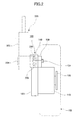
- FIG. 2 is a schematic view showing a structure for connecting the in-wheel motor 100 to the strut 200 forming a part of the suspension system.
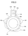
- FIG. 3 is a front view of the motor housing 110 and the gear housing 120.
- the fixing boss 148 is formed at an upper part of the gear housing 120.
- the fixing boss 140 is tightly fixed to a strut bracket 204 fixed to the strut shell 202 of the strut 200 by bolts 206.
- a connection boss 150 is formed uniformly with the motor housing 110 in a position corresponding to the fixing boss 148 of the gear housing 120.
- the motor housing 110 is connected to the gear housing 120 by plural bolts 152.
- the motor housing 110 is strongly and stably fixed to the gear housing 120 by connecting the connection boss 150 and fixing boss 148 via a bolt 154 so that it is possible to secure sufficient connection strength and rigidity.
- a single bolt 154 is used in the case shown in FIG. 3 , plural bolts may be used if necessary.
- connection boss 150 does not exist, the motor housing 110 comes in contact with the gear housing 120 only at a cylindrical thick part and therefore it may be difficult to obtain sufficient connection strength and rigidity.
- the contact part may be required to be thick. This may cause a large size or a heavy weight of the entire housing so that the ability of the suspension system may be degraded.
- connection boss 150 is formed in a position corresponding to the fixing boss necessary for fixing the housing to the suspension system, it is possible to minimize size and weight of the housing.
- the size of the fixing boss 148 for attaching the connection boss 150 is a size sufficient to secure the strength and rigidity necessary for connecting the motor housing 110 and the gear housing 120. Hence, it is possible to easily design the connection boss 150.
- connection boss 150 of the motor housing 110 is not fastened to the suspension system. That is, the motor housing 110 is indirectly connected to the suspension system via the connection boss 150 and the fixing boss 148. Therefore, high mechanical processing precision for combining the suspension system, the gear housing 120, and the motor housing 110 is not required. That is, only the precision between the suspension system and the gear housing 120, and the precision between the gear housing 120 and the motor housing 110 are required. Hence, not only is it possible to easily manufacture respective parts but also it is possible to make a design easily matching conditions required for the housing of the in-wheel motor because only precision between the two parts is required. In addition, it is possible to easily do the assembly work.
- FIG. 4-(a) and FIG. 4-(b) show a second embodiment of the present invention, more specifically another example of a housing structure of the present invention.
- the connection boss 150 is formed in a position corresponding to the fixing boss 148 formed in the motor housing 110 and the same effect as the effect in the case shown in FIG. 2 can be obtained.
- FIG. 4-(b) An example of an in-wheel motor not including the reduction gear is shown in FIG. 4-(b) .
- the cover member 110a of the motor housing 110 receiving the electric motor is arranged as the suspension side divided housing.
- the motor housing 110 is arranged as the connection side divided housing.
- the connection boss 150 is formed in a position corresponding to the fixing boss 148 formed in the cover member 110a and the seme effect as the effect in the case shown in FIG. 2 can be obtained. Therefore, high mechanical processing precision for combining the suspension system, the gear housing 120, and the motor housing 110 are not required. Hence, it is possible to easily manufacture and assemble respective parts.
- FIG. 5 shows a third embodiment of the present invention, more specifically an example where the housing of the in-wheel motor 100 is fitted in a beam type suspension system.
- FIG. 5-(a) is a rear view of the in-wheel motor 100 seen from a rear side of the vehicle.
- the in-wheel motor shown in FIG. 5 is formed by combining the motor housing 110 receiving the electric motor as the divided housing and the gear housing 120 receiving the reduction gear. If necessary, two or more divided housing can be combined.
- two or more divided housings have the corresponding unified fixing bosses 156 and 158 for fixing the suspension system.
- the fixing bosses 156 and 158 are fastened by a bolt 166 via an arm part 162 extending from a beam part 160 of the beam suspension system and an arm part bracket 164.
- the in-wheel motor 100 is formed by the divided housings, both of which are directly connected to the suspension system.
- the respective divided housings having the fixing bosses are directly connected to the suspension system so that a fitting span sufficient to obtain the necessary strength and rigidity for the connection between the suspension system and the in-wheel motor 100 can be easily secured.
- the arrangement of the electric motor and the reduction gear forming the in-wheel motor 100 may be opposite and the arrangement of the motor housing and the gear housing as the divided housings may be opposite.
- the in-wheel motor may be formed by only the electric motor and the divided housings may be formed by the cover member and the motor housing. In this case, the same effect as the effect in the example shown in FIG. 5-(a) and FIG. 5-(b) can be obtained.
- the configuration of the divided housing is not limited to the above-discussed embodiments.
- the suspension side divided housing has the fixing boss and the connection side housing has the connection boss situated in the position corresponding to the fixing boss
- configurations of other parts may be optionally selected and the same effect as the effect discussed above can be obtained.
- configurations of other parts may be optionally selected and the same effect as the effect discussed in the example shown in FIG. 5-(a) and FIG. 5-(b) can be obtained.
- the structure of the in-wheel motor shown in FIG. 1 is just an example of the present invention. As long as the in-wheel motor includes the electric motor received in the housing, the structure of the electric motor and the structure of the fitted reduction gear are optional and the same effect as the effect discussed above can be obtained.
Landscapes
- Engineering & Computer Science (AREA)
- Chemical & Material Sciences (AREA)
- Combustion & Propulsion (AREA)
- Transportation (AREA)
- Mechanical Engineering (AREA)
- Arrangement Or Mounting Of Propulsion Units For Vehicles (AREA)
- Vehicle Body Suspensions (AREA)
- Iron Core Of Rotating Electric Machines (AREA)
- Connection Of Motors, Electrical Generators, Mechanical Devices, And The Like (AREA)
- Motor Or Generator Frames (AREA)
Applications Claiming Priority (2)
| Application Number | Priority Date | Filing Date | Title |
|---|---|---|---|
| JP2004245886A JP4360305B2 (ja) | 2004-08-25 | 2004-08-25 | インホイールモータのハウジング構造 |
| EP05015553A EP1630026B1 (fr) | 2004-08-25 | 2005-07-18 | Structure de logement pour un moteur-roue |
Related Parent Applications (2)
| Application Number | Title | Priority Date | Filing Date |
|---|---|---|---|
| EP05015553A Division EP1630026B1 (fr) | 2004-08-25 | 2005-07-18 | Structure de logement pour un moteur-roue |
| EP05015553.0 Division | 2005-07-18 |
Publications (2)
| Publication Number | Publication Date |
|---|---|
| EP2106948A1 true EP2106948A1 (fr) | 2009-10-07 |
| EP2106948B1 EP2106948B1 (fr) | 2011-06-29 |
Family
ID=35431167
Family Applications (2)
| Application Number | Title | Priority Date | Filing Date |
|---|---|---|---|
| EP09166467A Expired - Lifetime EP2106948B1 (fr) | 2004-08-25 | 2005-07-18 | Structure de logement pour un moteur-roue |
| EP05015553A Expired - Lifetime EP1630026B1 (fr) | 2004-08-25 | 2005-07-18 | Structure de logement pour un moteur-roue |
Family Applications After (1)
| Application Number | Title | Priority Date | Filing Date |
|---|---|---|---|
| EP05015553A Expired - Lifetime EP1630026B1 (fr) | 2004-08-25 | 2005-07-18 | Structure de logement pour un moteur-roue |
Country Status (5)
| Country | Link |
|---|---|
| US (1) | US7735589B2 (fr) |
| EP (2) | EP2106948B1 (fr) |
| JP (1) | JP4360305B2 (fr) |
| CN (1) | CN1739994B (fr) |
| DE (1) | DE602005027153D1 (fr) |
Cited By (1)
| Publication number | Priority date | Publication date | Assignee | Title |
|---|---|---|---|---|
| JP2015160498A (ja) * | 2014-02-27 | 2015-09-07 | Ntn株式会社 | インホイールモータ駆動装置とダンパとの連結構造およびこの連結構造を備えるサスペンション装置 |
Families Citing this family (36)
| Publication number | Priority date | Publication date | Assignee | Title |
|---|---|---|---|---|
| CN100412605C (zh) * | 2004-04-13 | 2008-08-20 | 普乐士显示株式会社 | 色环装置及应用其的投影仪 |
| US7870917B2 (en) * | 2004-10-25 | 2011-01-18 | Sanyo Electric Co., Ltd. | Drive device for electrically movable vehicles and electric wheelchair having same |
| US7686145B2 (en) * | 2005-09-21 | 2010-03-30 | Sanyo Electric Co., Ltd. | Drive device for electrically movable vehicles and electric wheelchair having same |
| FR2898833B1 (fr) * | 2006-03-23 | 2008-12-05 | Conception & Dev Michelin Sa | Liaison au sol pour vehicule |
| DE102006023577A1 (de) * | 2006-05-19 | 2007-11-22 | Jungheinrich Ag | Radnabenantrieb für Flurförderzeuge |
| US20090267348A1 (en) * | 2008-04-23 | 2009-10-29 | Raanan Liebermann | Alternative energy generation systems for vehicles |
| US20100314187A1 (en) * | 2008-09-08 | 2010-12-16 | Chuan-Sheng Chen | Electric bicycle |
| FR2953773B1 (fr) | 2009-12-16 | 2012-04-27 | Michelin Soc Tech | Moyeu motorise comprenant des moyens de couplage et de decouplage. |
| DE112011100470A5 (de) * | 2010-02-07 | 2012-11-15 | Ksm Castings Gmbh | Achsmodul |
| DE202010017820U1 (de) | 2010-03-17 | 2012-11-29 | Compagnie Generale Des Etablissements Michelin | Motorisierte Nabe für eine elektrische Antriebsmaschine |
| DE102010029071A1 (de) * | 2010-05-18 | 2011-11-24 | Bayerische Motoren Werke Aktiengesellschaft | Radantrieb für ein Fahrzeug |
| FR2962079B1 (fr) * | 2010-07-01 | 2012-07-27 | Michelin Soc Tech | Moyeu motorise comprenant une machine electrique de traction. |
| JP5690153B2 (ja) * | 2011-01-21 | 2015-03-25 | Ntn株式会社 | インホイールモータ駆動装置 |
| FR2981614B1 (fr) | 2011-10-20 | 2013-11-01 | Michelin Soc Tech | Vehicule a traction electrique |
| FR2983787B1 (fr) | 2011-12-13 | 2013-11-29 | Michelin Soc Tech | Vehicule a traction electrique |
| WO2013100113A1 (fr) * | 2011-12-27 | 2013-07-04 | Okuda Katsuji | Générateur d'essieu de roue |
| KR101278914B1 (ko) * | 2012-01-09 | 2013-06-26 | 주식회사 만도 | 인휠 모터 시스템의 장착 구조체 |
| GB2487872B (en) * | 2012-05-09 | 2012-12-26 | Protean Electric Ltd | An electric motor or generator system |
| US9067500B2 (en) * | 2012-05-21 | 2015-06-30 | Krassimire Mihaylov Penev | Self rechargeable synergy drive for a motor vehicle |
| FR2993498B1 (fr) | 2012-07-20 | 2014-07-04 | Michelin & Cie | Moyeu motorise comprenant un changement de rapport et des moyens de couplage et de decouplage |
| KR20140014847A (ko) | 2012-07-26 | 2014-02-06 | 삼성테크윈 주식회사 | 모터 수리가 간편한 인휠 구동장치 |
| JP5932582B2 (ja) | 2012-09-12 | 2016-06-08 | Ntn株式会社 | インホイールモータ駆動装置のサスペンション構造 |
| JP5850259B2 (ja) * | 2012-11-28 | 2016-02-03 | 株式会社デンソー | 回転電機 |
| CN105009414B (zh) * | 2013-02-12 | 2017-09-29 | 日产自动车株式会社 | 旋转电机 |
| KR101462790B1 (ko) * | 2013-06-21 | 2014-11-20 | 현대위아 주식회사 | 전기 자동차용 리어 서스펜션 장착 구조 |
| JP6853622B2 (ja) * | 2015-09-29 | 2021-03-31 | Ntn株式会社 | インホイールモータ駆動装置、およびインホイールモータ駆動装置とサスペンション装置の連結構造 |
| JP6743446B2 (ja) * | 2016-03-25 | 2020-08-19 | 日産自動車株式会社 | インホイールモータ駆動装置 |
| JP6976083B2 (ja) * | 2016-09-21 | 2021-12-01 | Ntn株式会社 | 車両動力補助システムおよび車両従動輪回生システム |
| DE102017122017B4 (de) * | 2017-09-22 | 2020-03-12 | Saf-Holland Gmbh | Gehäuseeinheit und Achsendanordnung |
| JP6369614B1 (ja) * | 2017-09-29 | 2018-08-08 | トヨタ自動車株式会社 | 車両用ケーシング |
| US10965186B2 (en) * | 2018-08-01 | 2021-03-30 | Bendix Commercial Vehicle Systems Llc | Drum brake concept for use with an electric wheel end drive motor |
| KR102645080B1 (ko) * | 2019-06-27 | 2024-03-07 | 에이치엘만도 주식회사 | 인휠 모터용 연결 조립체 및 이를 포함하는 모빌리티 |
| FR3109481B1 (fr) * | 2020-04-15 | 2024-10-25 | Moving Magnet Tech | Motoréducteur compact |
| PL239426B1 (pl) * | 2020-09-07 | 2021-11-29 | Siec Badawcza Lukasiewicz Instytut Napedow I Masz Elektrycznych Komel | Konstrukcja wirnika silnika do zabudowy w piaście koła pojazdu |
| DE102023203216A1 (de) * | 2023-04-06 | 2024-10-10 | Vitesco Technologies GmbH | Antriebseinheit und Fahrzeug mit einer derartigen Einheit |
| CN119283550A (zh) * | 2024-11-27 | 2025-01-10 | 浙江吉利控股集团有限公司 | 悬架系统和具有其的车辆 |
Citations (4)
| Publication number | Priority date | Publication date | Assignee | Title |
|---|---|---|---|---|
| US5087229A (en) * | 1991-05-06 | 1992-02-11 | General Motors Corporation | Independently suspended steerable motor wheel apparatus |
| JPH05338446A (ja) | 1992-06-10 | 1993-12-21 | Aqueous Res:Kk | 車両用モータ駆動装置 |
| JP2001315534A (ja) | 2000-05-09 | 2001-11-13 | Nissan Motor Co Ltd | ホイールインモータ車のモータ搭載構造 |
| EP1362736A1 (fr) | 2001-02-19 | 2003-11-19 | Japan Science and Technology Corporation | Moteur roue pour automobiles electriques |
Family Cites Families (12)
| Publication number | Priority date | Publication date | Assignee | Title |
|---|---|---|---|---|
| US5180180A (en) * | 1991-04-24 | 1993-01-19 | Aisin Aw Co., Ltd. | Wheel supporting apparatus |
| US5472059A (en) * | 1994-02-15 | 1995-12-05 | Dana Corporation | Wheel end assembly |
| JP3337327B2 (ja) | 1994-08-04 | 2002-10-21 | 本田技研工業株式会社 | ホイールモータ |
| DE19524524A1 (de) * | 1995-07-05 | 1997-01-09 | Still Gmbh | Antriebsachse für ein Flurförderzeug |
| JP2000046157A (ja) | 1998-07-28 | 2000-02-18 | Equos Research Co Ltd | 車両用モータ駆動装置 |
| US20030230443A1 (en) * | 2002-01-08 | 2003-12-18 | David Cramer | Advanced composite hybrid-electric vehicle |
| JP2003211979A (ja) | 2002-01-17 | 2003-07-30 | Nsk Ltd | 電動式車輪駆動装置 |
| US20030155161A1 (en) * | 2002-02-20 | 2003-08-21 | Delphi Technologies Inc. | Integrated wheel bearing and motor |
| US6922004B2 (en) * | 2002-04-05 | 2005-07-26 | The Timken Company | Axial flux motor assembly |
| GB2389827B (en) * | 2002-06-18 | 2005-12-14 | Magnetic Systems Technology Lt | Hub drive system |
| JP4348941B2 (ja) * | 2002-11-26 | 2009-10-21 | 日産自動車株式会社 | 車輪用回転電機の取付構造 |
| US7137315B2 (en) * | 2004-07-30 | 2006-11-21 | Chao Lang Chang | Wheel hub having driving mechanism |
-
2004
- 2004-08-25 JP JP2004245886A patent/JP4360305B2/ja not_active Expired - Lifetime
-
2005
- 2005-06-24 US US11/165,039 patent/US7735589B2/en not_active Expired - Lifetime
- 2005-07-18 DE DE602005027153T patent/DE602005027153D1/de not_active Expired - Lifetime
- 2005-07-18 EP EP09166467A patent/EP2106948B1/fr not_active Expired - Lifetime
- 2005-07-18 EP EP05015553A patent/EP1630026B1/fr not_active Expired - Lifetime
- 2005-08-25 CN CN200510093097.6A patent/CN1739994B/zh not_active Expired - Lifetime
Patent Citations (4)
| Publication number | Priority date | Publication date | Assignee | Title |
|---|---|---|---|---|
| US5087229A (en) * | 1991-05-06 | 1992-02-11 | General Motors Corporation | Independently suspended steerable motor wheel apparatus |
| JPH05338446A (ja) | 1992-06-10 | 1993-12-21 | Aqueous Res:Kk | 車両用モータ駆動装置 |
| JP2001315534A (ja) | 2000-05-09 | 2001-11-13 | Nissan Motor Co Ltd | ホイールインモータ車のモータ搭載構造 |
| EP1362736A1 (fr) | 2001-02-19 | 2003-11-19 | Japan Science and Technology Corporation | Moteur roue pour automobiles electriques |
Non-Patent Citations (1)
| Title |
|---|
| PATENT ABSTRACTS OF JAPAN vol. 2002, no. 03 3 April 2002 (2002-04-03) * |
Cited By (1)
| Publication number | Priority date | Publication date | Assignee | Title |
|---|---|---|---|---|
| JP2015160498A (ja) * | 2014-02-27 | 2015-09-07 | Ntn株式会社 | インホイールモータ駆動装置とダンパとの連結構造およびこの連結構造を備えるサスペンション装置 |
Also Published As
| Publication number | Publication date |
|---|---|
| CN1739994A (zh) | 2006-03-01 |
| JP4360305B2 (ja) | 2009-11-11 |
| CN1739994B (zh) | 2010-11-24 |
| US20060087182A1 (en) | 2006-04-27 |
| EP1630026A2 (fr) | 2006-03-01 |
| DE602005027153D1 (de) | 2011-05-12 |
| EP2106948B1 (fr) | 2011-06-29 |
| JP2006062476A (ja) | 2006-03-09 |
| EP1630026B1 (fr) | 2011-03-30 |
| EP1630026A3 (fr) | 2006-03-22 |
| US7735589B2 (en) | 2010-06-15 |
Similar Documents
| Publication | Publication Date | Title |
|---|---|---|
| EP2106948B1 (fr) | Structure de logement pour un moteur-roue | |
| JP3960553B1 (ja) | インホイールモータ車のホイール回転装置 | |
| JP3349627B2 (ja) | 減速機付き電動機およびその製造方法 | |
| JP5461580B2 (ja) | 電動モータホイール構造体 | |
| US20040112657A1 (en) | Installation structure for electric rotating machine in motor vehicle | |
| JP2019048613A (ja) | 車輪用軸受装置およびこの車輪用軸受装置を備えた車両 | |
| KR101724787B1 (ko) | 인휠모터시스템 | |
| WO2019078215A1 (fr) | Dispositif d'alimentation pour véhicules | |
| JP4088770B2 (ja) | インホイールモータ | |
| WO2019202916A1 (fr) | Rotor, moteur et moteur d'essuie-glace sans balais | |
| WO2020162400A1 (fr) | Dispositif de puissance de véhicule pourvu d'un moteur électrique et roulement de roue fixé sur un générateur, pourvu d'un générateur | |
| JP5292626B2 (ja) | インホイールモータ駆動装置およびインホイールモータ駆動装置用ケーシング | |
| JP2012125014A (ja) | 車載用回転電機および電動車両 | |
| JPH08149753A (ja) | 減速機付モータ | |
| JPH09132040A (ja) | 減速機付きホイールモータ | |
| JP2019205241A (ja) | 三相永久磁石同期モータおよびこの三相永久磁石同期モータを備えた車両用動力装置、発電機およびこの発電機を備えた発電機付車輪用軸受 | |
| WO2012014969A1 (fr) | Moteur moulé et corps mobile monté avec celui-ci | |
| JP2006304558A (ja) | モータ組込みハイポサイクロイド減速機 | |
| JP3047798B2 (ja) | 車両用駆動装置 | |
| JPH08168226A (ja) | 減速機付モータ | |
| CN117155052A (zh) | 电动车辆用马达 | |
| JP2004120910A (ja) | インホイールモータの配線構造 | |
| JPH0848157A (ja) | ホイールモータ | |
| JP7828811B2 (ja) | モータ、車両 | |
| JP2869926B2 (ja) | ホイールモータ |
Legal Events
| Date | Code | Title | Description |
|---|---|---|---|
| PUAI | Public reference made under article 153(3) epc to a published international application that has entered the european phase |
Free format text: ORIGINAL CODE: 0009012 |
|
| 17P | Request for examination filed |
Effective date: 20090727 |
|
| AC | Divisional application: reference to earlier application |
Ref document number: 1630026 Country of ref document: EP Kind code of ref document: P |
|
| AK | Designated contracting states |
Kind code of ref document: A1 Designated state(s): DE FR GB |
|
| GRAP | Despatch of communication of intention to grant a patent |
Free format text: ORIGINAL CODE: EPIDOSNIGR1 |
|
| GRAS | Grant fee paid |
Free format text: ORIGINAL CODE: EPIDOSNIGR3 |
|
| GRAA | (expected) grant |
Free format text: ORIGINAL CODE: 0009210 |
|
| AC | Divisional application: reference to earlier application |
Ref document number: 1630026 Country of ref document: EP Kind code of ref document: P |
|
| AK | Designated contracting states |
Kind code of ref document: B1 Designated state(s): DE FR GB |
|
| REG | Reference to a national code |
Ref country code: GB Ref legal event code: FG4D |
|
| REG | Reference to a national code |
Ref country code: DE Ref legal event code: R096 Ref document number: 602005028822 Country of ref document: DE Effective date: 20110818 |
|
| PLBE | No opposition filed within time limit |
Free format text: ORIGINAL CODE: 0009261 |
|
| STAA | Information on the status of an ep patent application or granted ep patent |
Free format text: STATUS: NO OPPOSITION FILED WITHIN TIME LIMIT |
|
| 26N | No opposition filed |
Effective date: 20120330 |
|
| REG | Reference to a national code |
Ref country code: DE Ref legal event code: R097 Ref document number: 602005028822 Country of ref document: DE Effective date: 20120330 |
|
| REG | Reference to a national code |
Ref country code: GB Ref legal event code: 746 Effective date: 20130412 |
|
| REG | Reference to a national code |
Ref country code: DE Ref legal event code: R084 Ref document number: 602005028822 Country of ref document: DE Effective date: 20130410 |
|
| REG | Reference to a national code |
Ref country code: FR Ref legal event code: PLFP Year of fee payment: 12 |
|
| REG | Reference to a national code |
Ref country code: FR Ref legal event code: PLFP Year of fee payment: 13 |
|
| REG | Reference to a national code |
Ref country code: FR Ref legal event code: PLFP Year of fee payment: 14 |
|
| P01 | Opt-out of the competence of the unified patent court (upc) registered |
Effective date: 20230427 |
|
| PGFP | Annual fee paid to national office [announced via postgrant information from national office to epo] |
Ref country code: GB Payment date: 20240530 Year of fee payment: 20 |
|
| PGFP | Annual fee paid to national office [announced via postgrant information from national office to epo] |
Ref country code: FR Payment date: 20240611 Year of fee payment: 20 |
|
| PGFP | Annual fee paid to national office [announced via postgrant information from national office to epo] |
Ref country code: DE Payment date: 20240529 Year of fee payment: 20 |
|
| REG | Reference to a national code |
Ref country code: DE Ref legal event code: R071 Ref document number: 602005028822 Country of ref document: DE |
|
| REG | Reference to a national code |
Ref country code: GB Ref legal event code: PE20 Expiry date: 20250717 |