EP2106971A1 - Lichtemittierende Anzeigevorrichtung mit Rückspiegel - Google Patents
Lichtemittierende Anzeigevorrichtung mit Rückspiegel Download PDFInfo
- Publication number
- EP2106971A1 EP2106971A1 EP09001692A EP09001692A EP2106971A1 EP 2106971 A1 EP2106971 A1 EP 2106971A1 EP 09001692 A EP09001692 A EP 09001692A EP 09001692 A EP09001692 A EP 09001692A EP 2106971 A1 EP2106971 A1 EP 2106971A1
- Authority
- EP
- European Patent Office
- Prior art keywords
- light
- dark color
- mask member
- color mask
- display device
- Prior art date
- Legal status (The legal status is an assumption and is not a legal conclusion. Google has not performed a legal analysis and makes no representation as to the accuracy of the status listed.)
- Granted
Links
- 125000006850 spacer group Chemical group 0.000 claims abstract description 29
- 239000000758 substrate Substances 0.000 claims abstract description 28
- 230000002093 peripheral effect Effects 0.000 claims abstract description 7
- 239000010408 film Substances 0.000 description 105
- 239000003973 paint Substances 0.000 description 32
- 239000000463 material Substances 0.000 description 20
- 239000004793 Polystyrene Substances 0.000 description 9
- GWEVSGVZZGPLCZ-UHFFFAOYSA-N Titan oxide Chemical compound O=[Ti]=O GWEVSGVZZGPLCZ-UHFFFAOYSA-N 0.000 description 8
- 239000011347 resin Substances 0.000 description 8
- 229920005989 resin Polymers 0.000 description 8
- VYPSYNLAJGMNEJ-UHFFFAOYSA-N Silicium dioxide Chemical compound O=[Si]=O VYPSYNLAJGMNEJ-UHFFFAOYSA-N 0.000 description 6
- 230000004313 glare Effects 0.000 description 5
- 239000004743 Polypropylene Substances 0.000 description 4
- 239000003086 colorant Substances 0.000 description 4
- XECAHXYUAAWDEL-UHFFFAOYSA-N acrylonitrile butadiene styrene Chemical compound C=CC=C.C=CC#N.C=CC1=CC=CC=C1 XECAHXYUAAWDEL-UHFFFAOYSA-N 0.000 description 3
- 239000004676 acrylonitrile butadiene styrene Substances 0.000 description 3
- 229920000122 acrylonitrile butadiene styrene Polymers 0.000 description 3
- PNEYBMLMFCGWSK-UHFFFAOYSA-N aluminium oxide Inorganic materials [O-2].[O-2].[O-2].[Al+3].[Al+3] PNEYBMLMFCGWSK-UHFFFAOYSA-N 0.000 description 3
- 229910052681 coesite Inorganic materials 0.000 description 3
- 229910052593 corundum Inorganic materials 0.000 description 3
- 229910052906 cristobalite Inorganic materials 0.000 description 3
- 238000010586 diagram Methods 0.000 description 3
- 239000000377 silicon dioxide Substances 0.000 description 3
- 239000005361 soda-lime glass Substances 0.000 description 3
- 229910052682 stishovite Inorganic materials 0.000 description 3
- PBCFLUZVCVVTBY-UHFFFAOYSA-N tantalum pentoxide Inorganic materials O=[Ta](=O)O[Ta](=O)=O PBCFLUZVCVVTBY-UHFFFAOYSA-N 0.000 description 3
- 238000002834 transmittance Methods 0.000 description 3
- 229910052905 tridymite Inorganic materials 0.000 description 3
- 229910001845 yogo sapphire Inorganic materials 0.000 description 3
- MCMNRKCIXSYSNV-UHFFFAOYSA-N Zirconium dioxide Chemical compound O=[Zr]=O MCMNRKCIXSYSNV-UHFFFAOYSA-N 0.000 description 2
- NIXOWILDQLNWCW-UHFFFAOYSA-N acrylic acid group Chemical group C(C=C)(=O)O NIXOWILDQLNWCW-UHFFFAOYSA-N 0.000 description 2
- 238000009500 colour coating Methods 0.000 description 2
- 230000000694 effects Effects 0.000 description 2
- 238000005259 measurement Methods 0.000 description 2
- ZKATWMILCYLAPD-UHFFFAOYSA-N niobium pentoxide Chemical compound O=[Nb](=O)O[Nb](=O)=O ZKATWMILCYLAPD-UHFFFAOYSA-N 0.000 description 2
- -1 polypropylene Polymers 0.000 description 2
- 239000004800 polyvinyl chloride Substances 0.000 description 2
- 229920000915 polyvinyl chloride Polymers 0.000 description 2
- 230000003746 surface roughness Effects 0.000 description 2
- BZHJMEDXRYGGRV-UHFFFAOYSA-N Vinyl chloride Chemical compound ClC=C BZHJMEDXRYGGRV-UHFFFAOYSA-N 0.000 description 1
- 229920000800 acrylic rubber Polymers 0.000 description 1
- 229920001893 acrylonitrile styrene Polymers 0.000 description 1
- 238000000149 argon plasma sintering Methods 0.000 description 1
- 230000007423 decrease Effects 0.000 description 1
- 238000000151 deposition Methods 0.000 description 1
- 230000002542 deteriorative effect Effects 0.000 description 1
- 230000002349 favourable effect Effects 0.000 description 1
- 239000011521 glass Substances 0.000 description 1
- 238000009499 grossing Methods 0.000 description 1
- 229910052736 halogen Inorganic materials 0.000 description 1
- 150000002367 halogens Chemical class 0.000 description 1
- 239000004973 liquid crystal related substance Substances 0.000 description 1
- 229910001635 magnesium fluoride Inorganic materials 0.000 description 1
- 239000002184 metal Substances 0.000 description 1
- 229910052751 metal Inorganic materials 0.000 description 1
- 239000007769 metal material Substances 0.000 description 1
- 230000003287 optical effect Effects 0.000 description 1
- 239000012788 optical film Substances 0.000 description 1
- 229920003229 poly(methyl methacrylate) Polymers 0.000 description 1
- 229920000058 polyacrylate Polymers 0.000 description 1
- 239000004926 polymethyl methacrylate Substances 0.000 description 1
- 229920001155 polypropylene Polymers 0.000 description 1
- 229920002223 polystyrene Polymers 0.000 description 1
- 230000002265 prevention Effects 0.000 description 1
- SCUZVMOVTVSBLE-UHFFFAOYSA-N prop-2-enenitrile;styrene Chemical compound C=CC#N.C=CC1=CC=CC=C1 SCUZVMOVTVSBLE-UHFFFAOYSA-N 0.000 description 1
- 230000003595 spectral effect Effects 0.000 description 1
Images


Classifications
-
- B—PERFORMING OPERATIONS; TRANSPORTING
- B60—VEHICLES IN GENERAL
- B60R—VEHICLES, VEHICLE FITTINGS, OR VEHICLE PARTS, NOT OTHERWISE PROVIDED FOR
- B60R1/00—Optical viewing arrangements; Real-time viewing arrangements for drivers or passengers using optical image capturing systems, e.g. cameras or video systems specially adapted for use in or on vehicles
- B60R1/12—Mirror assemblies combined with other articles, e.g. clocks
-
- G—PHYSICS
- G02—OPTICS
- G02B—OPTICAL ELEMENTS, SYSTEMS OR APPARATUS
- G02B5/00—Optical elements other than lenses
- G02B5/08—Mirrors
- G02B5/0816—Multilayer mirrors, i.e. having two or more reflecting layers
- G02B5/0825—Multilayer mirrors, i.e. having two or more reflecting layers the reflecting layers comprising dielectric materials only
- G02B5/0833—Multilayer mirrors, i.e. having two or more reflecting layers the reflecting layers comprising dielectric materials only comprising inorganic materials only
-
- G—PHYSICS
- G02—OPTICS
- G02B—OPTICAL ELEMENTS, SYSTEMS OR APPARATUS
- G02B5/00—Optical elements other than lenses
- G02B5/20—Filters
- G02B5/26—Reflecting filters
-
- B—PERFORMING OPERATIONS; TRANSPORTING
- B60—VEHICLES IN GENERAL
- B60R—VEHICLES, VEHICLE FITTINGS, OR VEHICLE PARTS, NOT OTHERWISE PROVIDED FOR
- B60R1/00—Optical viewing arrangements; Real-time viewing arrangements for drivers or passengers using optical image capturing systems, e.g. cameras or video systems specially adapted for use in or on vehicles
- B60R1/12—Mirror assemblies combined with other articles, e.g. clocks
- B60R2001/1253—Mirror assemblies combined with other articles, e.g. clocks with cameras, video cameras or video screens
Definitions
- the present invention relates to a rear-view mirror incorporating a light-emitting display device, which prevents interference of light from occurring where a dark color mask member is arranged behind a mirror element.
- Japanese Patent Laid-Open Nos. 2000-153736 and 2000-255321 each discloses a rear-view mirror incorporating a light-emitting display device to display information.
- the rear-view mirror disclosed in Japanese Patent Laid-Open No. 2000-153736 is formed by: forming a semi-transmissive reflective film formed of a dielectric multilayer film on the back surface of a mirror substrate; forming a colored paint film on the region excluding a part of the entire region of the back surface of the semi-transmissive reflective film; forming a transparent paint film or a semi-transparent paint film on the region of the back surface of the semi-transmissive reflective film where the colored paint film is not formed; and arranging a monitor device on the back side of the region of the mirror substrate where the transparent paint film or the semi-transparent paint film is formed.
- the colors of the colored paint film and the screen of the monitor device are set so that when the monitor device is off, the colored paint film and the screen of the monitor device have colors that are substantially the same (black). Consequently, when the monitor device is off, the boundary between the colored paint film and the screen of the monitor device is unclear, preventing the mirror visibility from being lowered by the boundary.
- the rear-view mirror disclosed in Japanese Patent Laid-Open No. 2000-255321 is formed by: forming a semi-transmissive reflective film formed of a dielectric multilayer film on the back surface of a mirror substrate, arranging a colored plate in a region excluding a part of the entire region of the back side of the semi-transmissive reflective film, in contact with the semi-transmissive reflective film, and arranging a monitor device on the region of the back surface of the semi-transmissive reflective film where the colored plate is not arranged.
- the colors of the colored plate and the screen of the monitor device are set so that when the monitor device is off, the colored plate and the screen of the monitor device have colors that are substantially the same (black). Consequently, when the monitor device is off, the boundary between the colored plate and the screen of the monitor device is unclear, preventing the mirror visibility from being lowered by the boundary.
- the present invention has been made in view of the aforementioned points, and aims to provide a light-emitting display device-equipped rear-view mirror that prevents interference of light from occurring when a dark color mask member is arranged behind a mirror element.
- the present invention comprises: a mirror element having a semi-transmissive reflective film on one surface of a transparent substrate; a dark color mask member having an opening in a surface thereof, the mask member being arranged facing an entire region excluding a region facing the opening or a relevant region excluding the region facing the opening, of a back surface of the mirror element, at least a front surface of the mask member being of a dark color; and a spacer arranged between the transparent substrate and the dark color mask member and providing a clearance gap between the transparent substrate and the dark color mask member; and a light-emitting display device arranged at a position behind the mirror element, with a display surface facing the opening of the dark color mask member, wherein a distance provided by the clearance gap between the transparent substrate and the dark color mask member is set to a distance that prevents interference of light from occurring between light reflected by the back surface of the mirror element and light reflected by the front surface of the dark color mask member.
- a spacer is arranged between a transparent substrate and a dark color mask member to form a clearance gap providing a distance that prevents interference of light from occurring between the transparent substrate and the dark color mask member, and as a result, interference of light is prevented, enabling provision of an improved design and mirror visibility.
- the distance provided by the clearance gap can be set to, for example, no less than 0.3 mm and no more than 5 mm.
- the spacer can be formed of, for example, a protrusion protruding from a peripheral edge of a surface of the dark color mask member facing the mirror element.
- the spacer can be formed as a body separated from the dark color mask member. It is desirable that the front surface of the dark color mask member facing the mirror element be smooth, and an arithmetic average roughness Ra of the front surface can be, for example, no more than 0.6 ⁇ m. As a result of smoothing the front surface of the dark color mask member, light scattering on the surface of the dark color mask member is suppressed, enabling provision of a more favorable design and mirror visibility.
- the semi-transmissive reflective film can be formed of, for example, a dielectric multilayer film.
- a reflection peak wavelength in a visible light range of the mirror element can be set to, for example, from 430 nm to 630 nm, preferably, from 500 nm to 550 nm.
- FIG. 1 illustrates an overview of the inner structure of a vehicle inner mirror to which the present invention has been applied.
- FIG. 1A is a front view
- FIG. 1B is a cross-sectional view taken along a line indicated by arrows A-A in FIG. 1A .
- An inner mirror 10 is formed by putting a mirror element 14 into a front surface opening 12a of a housing 12.
- the mirror element 14 is formed as a back-surface mirror having a semi-transmissive reflective film 18, which is formed of a dielectric multilayer film, on the entire back surface of a transparent substrate 16, which is formed of, e.g., transparent glass or transparent optical resin.
- a dark color (for example, black) mask member 20 is arranged facing the back side of the mirror element 14 across a clearance gap 19 providing a predetermined distance d between the mirror element 14 and the dark color mask member 20.
- An opening 20a is formed at the relevant region of the dark color mask member 20 (in FIGS. 1A and 1B , the right corner of the surface of the mirror element 14 close to a driver's viewpoint).
- the dark color mask member 20 is arranged facing the entire back surface of the mirror element 14 excluding the position of the opening 20a.
- a light-emitting display device 22 is arranged at a position behind the mirror element 14, with a display surface 22a facing the opening 20a of the dark color mask member 20.
- the distance provided by the clearance gap 19 at any position where the light-emitting display device 22 and the mirror element 14 face each other is set to the distance d provided by the clearance gap at the position where the dark color mask member 20 and the mirror element 14 face each other or larger.
- the light-emitting display device 22 does not protrude forward from the front surface 20b of the dark color mask member 20.
- the light-emitting display device 22 may be, e.g., a liquidcrystal display device or an EL display device.
- the color of the display surface 22a of the light-emitting display device 22 is set so that it is substantially the same as that of the front surface 20b of the dark color mask member 20 (for example, black) when the light-emitting display device 22 is off.
- the light-emitting display device 22 is supported by being attached to the dark color mask member 20 or supported by being attached to a relevant part of the inside of the housing 12.
- the dark color mask member 20 can be formed of a dark color resin made of, e.g., PP (polypropylene), PVC (polyvinyl chloride), ASA (acrylonitrile styrene acrylic rubber), PS (polystyrene) or ABS (acrylonitrile butadiene styrene) or a resin with at least its front surface provided with dark color coating, or can also be formed of, e.g., a plate of metal, e.g., Al or Fe provided with dark color coating, and in all the cases, a material which has the color tone closest to that of the display surface 22a when the light-emitting display device 22 is off is preferable. Also, from the viewpoint of lightweight, resin materials are more preferable than metal materials.
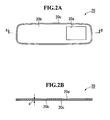
- FIGS. 2A and 2B illustrate the structure of the dark color mask member 20.
- FIG. 2A is a front view
- FIG. 2B is a cross-sectional view taken along a line indicated by arrows B-B in FIG. 2A .
- the entire of the dark color mask member 20 is integrally formed of, e.g., a dark color resin plate.
- the front shape of the dark color mask member 20 has the same outer shape as that of the mirror element 14, and a protrusion 20c forming a spacer is integrated with the entire peripheral edge of the front surface (the surface facing the mirror element 14) 20b of the dark color mask member 20.
- the spacer 20c has a rectangular shape in cross section, and the height d of the spacer is set to be equal to the distance d provided by a clearance gap 19 between the mirror element 14 and the dark color mask member 20, which is provided by the spacer 20c. In the surface surrounded by the spacer 20c of the dark color mask member 20, the opening 20a is formed.
- a groove 12b is formed around the entire circumference of the inner wall surface of the opening 12a of the housing 12, and the mirror element 14 and the dark color mask member 20 are put together and put into the groove 12b.
- the mirror element 14 enters a state in which the entire peripheral edge of its back surface is in contact with the top surface of the spacer 20c.
- the mirror element 14 and the dark color mask member 20 are kept facing each other across the distance d provided by the clearance gap 19 therebetween.
- the distance d provided by the clearance gap 19 is a distance that prevents interference of light from occurring between light reflected by the back surface of the mirror element 14 and light reflected by the front surface of the dark color mask member 20, and is preferably no less than 0.3 mm, for example. Furthermore, if the distance d provided by the clearance gap 19 is overly large, the thickness of the housing 12 will increase, and accordingly, it is desirable that the distance d is no more than 5 mm.
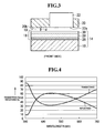
- FIG. 3 schematically illustrates the film configuration of the semi-transmissive reflective film 18.
- the transparent substrate 16 is formed of, for example, soda lime glass.
- the semi-transmissive reflective film 18 is formed on the back surface of the transparent substrate 16.
- the semi-transmissive reflective film 18 formed of a dielectric multilayer film obtained by sequentially depositing three films, i.e., a high refractive index material film 26, a low refractive index material film 28 and a high refractive index material film 30, is formed on the back surface of the transparent substrate 16.
- Each of the films 26, 28 and 30 is formed of a material that absorbs no visible light or absorbs an extremely small amount of visible light.
- the high refractive index material films 26 and 30 can be formed of, for example, TiO 2 , Ta 2 O 5 , ZrO 2 , Nb 2 O 5 , etc.
- the low refractive index material film 28 is formed of, for example, SiO 2 , Al 2 O 3 , MgF 2 , etc.
- FIG. 4 shows an example of the reflectance characteristics and the transmittance characteristics of the mirror element 14 shown in FIG. 3 where the high refractive index material films 26 and 30 are each formed of TiO 2 and the low refractive index material film 28 is formed of SiO 2 .
- the characteristics exhibit a single reflection peak in the visible light range. According to the characteristics, the reflectance necessary for a vehicle mirror can be obtained. Also, the reflection peak wavelength in the visible light range is approximately 530 nm, and the reflectance for that wavelength is approximately 60%. Accordingly, glare that a cold mirror may give will not be given to drivers.
- the reflectance gently decreases at both sides of the reflection peak wavelength, it is possible to reduce the reflected light intensity for both bluish short-wavelength range light from a discharge lamp and reddish long wavelength range light from a halogen lamp, making it possible to obtain a higher glare prevention effect.
- the high refractive index material films of the semi-transmissive reflective film 18 are formed of TiO 2 and the low refractive index material film is formed of SiO 2 , the integrating sphere visible reflectance becomes overly high if five or more layers are deposited, resulting in that headlight from behind makes a driver have the feeling of glare at night.
- the spectral shape of the reflected light sharply changes, and as a result, problems arise, for example, in that the mirror element 14 provides no natural tone and becomes unsuitable for a mirror, and moreover, and that its view angle dependency increases, causing a discontinuous part in the tone of reflected light. Therefore, three or four layers are suitable for the laminated layers of the semi-transmissive reflective film 18.
- FIG. 5A schematically illustrates light reflection by the rear-view mirror according to Japanese Patent Laid-Open No. 2000-153736 (the same reference numerals are provided to the parts that are in common with those in FIG. 1 ).
- a semi-transmissive reflective film 18 is formed on the back surface of a transparent substrate 16.
- a transparent paint film or a semi-transparent paint film 32 is formed at the region of the back surface of the semi-transmissive reflective film 18 where a light-emitting display device 22 is arranged, and a black colored paint film 34 is formed at the remaining region.
- the transparent substrate 16 is formed of soda lime glass
- the semi-transmissive reflective film 18 is formed of a dielectric multilayer film formed of three layers of Ta 2 O 5 (high refractive index material film) - Al 2 O 3 (low refractive index material film) - TiO 2 (high refractive index material film).
- the integrating sphere visible reflectances in this case are:
- FIG. 5B schematically illustrates light reflection by the rear-view mirror in FIG. 1 .
- the transparent substrate 16 is formed of soda lime glass
- the semi-transmissive reflective film 18 is formed of a dielectric multilayer film having three layers of Ta 2 O 5 (high refractive index material film) - Al 2 O 3 (low refractive index material film) - TiO 2 (high refractive index material film).
- the integrating sphere visible reflectances in this case are:
- FIGS. 6A and 6B show differences in light reflection on the front surface 20b between the case where the front surface 20b of the dark color mask member 20 is rough and the case where the front surface 20b of the dark color mask member 20 is smooth.
- FIG. 6A shows the case where the front surface 20b is rough (the arithmetic average roughness Ra of the front surface is more than 0.6 ⁇ m). Incident light in this case is reflected by the front surface 20b and generates a large amount of scattering light, and the reflected light turns to a whitish color tone.
- FIG. 6B shows the case where the front surface 20b is smooth (the arithmetic average roughness Ra of the front surface is no more than 0.6 ⁇ m).
- the front surface 20b When the front surface 20b is smooth, the generation of scattering light is suppressed and consequently, the difference in color tone between the region where the dark color mask member 20 having the smooth front surface and the region where the light-emitting display device 22 having a smooth front surface becomes small, and as a result, the two regions cannot easily be distinguished visually, providing a good design. Furthermore, since a smaller amount of scattering light is generated compared to the case where the front surface of the dark color mask member 20 is rough, glare and a feeling of discomfort given to a driver can be reduced, enabling provision of a safer visibility.
- the following table shows the results of preparing samples of the dark color mask member 20 made of various resin materials and measuring the arithmetic average roughness Ra of the front surface and the amount of scattering light for each of the samples.
- the front surface of the arithmetic average roughness Ra was measured using a Keyence laser microscope, and the amount of scattering light was observed visually.
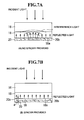
- FIGS. 7A and 7B show differences in reflection between the case where no spacer 20c is provided and the case where a spacer 20c is provided.
- FIG. 7A illustrates the case where no spacer 20c is provided.
- FIG. 7B illustrates the case where a spacer 20c is provided.
- a clearance gap 19 is formed between the semi-transmissive reflective film 18 and the dark color mask member 20, and consequently, a sufficient distance is provided between the semi-transmissive reflective film 18 and the dark color mask member 20.
- light reflected by the back surface 18a of the semi-transmissive reflective film 18 and light reflected by the front surface 20a of the dark color mask member 20 do not interfere with each other, generating no interference light.
- the height d of the spacer 20c is set to no less than 0.3 mm, which is sufficient to avoid the semi-transmissive reflective film 18 and the dark color mask member 20 from coming into contact with each other even if an external force is applied to the mirror element 14, generation of interference light can be prevented. Also, where the height d of the spacer 20c is overly high, the thickness of the housing 12 ( FIG. 1B ) will be large, and accordingly, it is desirable that the height d of the spacer 20c be no more than 5 mm.
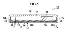
- FIG. 8 illustrates an embodiment including a spacer formed in such a manner.
- FIG. 8 is a cross-sectional view taken from a line corresponding to a line indicated by arrows A-A in FIG. 1A .
- the parts that are in common with those in FIG. 1 are provided with the same reference numerals.
- An inner mirror 36 has a clearance gap 19 providing a distance d between the mirror element 14 and the dark color mask member 20 by providing a spacer 38 between the entire peripheral edges of the mirror element 14 and the dark color mask member 20.
- the spacer 38 is formed of, e.g., a ring-shaped, dark color (for example, black) resin member.
Landscapes
- Physics & Mathematics (AREA)
- General Physics & Mathematics (AREA)
- Optics & Photonics (AREA)
- Engineering & Computer Science (AREA)
- Chemical & Material Sciences (AREA)
- Inorganic Chemistry (AREA)
- Multimedia (AREA)
- Mechanical Engineering (AREA)
- Optical Elements Other Than Lenses (AREA)
Applications Claiming Priority (1)
| Application Number | Priority Date | Filing Date | Title |
|---|---|---|---|
| JP2008090323A JP4695665B2 (ja) | 2008-03-31 | 2008-03-31 | 発光表示装置付きバックミラー |
Publications (2)
| Publication Number | Publication Date |
|---|---|
| EP2106971A1 true EP2106971A1 (de) | 2009-10-07 |
| EP2106971B1 EP2106971B1 (de) | 2012-04-18 |
Family
ID=40624314
Family Applications (1)
| Application Number | Title | Priority Date | Filing Date |
|---|---|---|---|
| EP09001692A Expired - Fee Related EP2106971B1 (de) | 2008-03-31 | 2009-02-06 | Lichtemittierende Anzeigevorrichtung mit Rückspiegel |
Country Status (3)
| Country | Link |
|---|---|
| US (1) | US7980711B2 (de) |
| EP (1) | EP2106971B1 (de) |
| JP (1) | JP4695665B2 (de) |
Cited By (3)
| Publication number | Priority date | Publication date | Assignee | Title |
|---|---|---|---|---|
| EP2251228A3 (de) * | 2009-05-15 | 2012-03-07 | SMR Patents S.à.r.l. | Fahrzeuginnenspiegelvorrichtung zum Anzeigen von Bildern |
| US9448449B2 (en) | 2013-01-31 | 2016-09-20 | Venkataraman Ramanathan | Glare reduction system |
| US9601083B2 (en) | 2013-03-18 | 2017-03-21 | Venkataraman Ramanathan | Glare reduction system |
Families Citing this family (89)
| Publication number | Priority date | Publication date | Assignee | Title |
|---|---|---|---|---|
| US5910854A (en) | 1993-02-26 | 1999-06-08 | Donnelly Corporation | Electrochromic polymeric solid films, manufacturing electrochromic devices using such solid films, and processes for making such solid films and devices |
| US5668663A (en) | 1994-05-05 | 1997-09-16 | Donnelly Corporation | Electrochromic mirrors and devices |
| US6891563B2 (en) * | 1996-05-22 | 2005-05-10 | Donnelly Corporation | Vehicular vision system |
| US6172613B1 (en) | 1998-02-18 | 2001-01-09 | Donnelly Corporation | Rearview mirror assembly incorporating vehicle information display |
| US6124886A (en) | 1997-08-25 | 2000-09-26 | Donnelly Corporation | Modular rearview mirror assembly |
| US6326613B1 (en) | 1998-01-07 | 2001-12-04 | Donnelly Corporation | Vehicle interior mirror assembly adapted for containing a rain sensor |
| US8294975B2 (en) | 1997-08-25 | 2012-10-23 | Donnelly Corporation | Automotive rearview mirror assembly |
| US6445287B1 (en) | 2000-02-28 | 2002-09-03 | Donnelly Corporation | Tire inflation assistance monitoring system |
| US8288711B2 (en) | 1998-01-07 | 2012-10-16 | Donnelly Corporation | Interior rearview mirror system with forwardly-viewing camera and a control |
| US6477464B2 (en) | 2000-03-09 | 2002-11-05 | Donnelly Corporation | Complete mirror-based global-positioning system (GPS) navigation solution |
| US6693517B2 (en) | 2000-04-21 | 2004-02-17 | Donnelly Corporation | Vehicle mirror assembly communicating wirelessly with vehicle accessories and occupants |
| US6329925B1 (en) | 1999-11-24 | 2001-12-11 | Donnelly Corporation | Rearview mirror assembly with added feature modular display |
| US7167796B2 (en) | 2000-03-09 | 2007-01-23 | Donnelly Corporation | Vehicle navigation system for use with a telematics system |
| US7370983B2 (en) | 2000-03-02 | 2008-05-13 | Donnelly Corporation | Interior mirror assembly with display |
| AU2001243285A1 (en) | 2000-03-02 | 2001-09-12 | Donnelly Corporation | Video mirror systems incorporating an accessory module |
| US7255451B2 (en) | 2002-09-20 | 2007-08-14 | Donnelly Corporation | Electro-optic mirror cell |
| US7581859B2 (en) | 2005-09-14 | 2009-09-01 | Donnelly Corp. | Display device for exterior rearview mirror |
| WO2002062623A2 (en) | 2001-01-23 | 2002-08-15 | Donnelly Corporation | Improved vehicular lighting system for a mirror assembly |
| US6918674B2 (en) | 2002-05-03 | 2005-07-19 | Donnelly Corporation | Vehicle rearview mirror system |
| AU2003237424A1 (en) | 2002-06-06 | 2003-12-22 | Donnelly Corporation | Interior rearview mirror system with compass |
| US7329013B2 (en) | 2002-06-06 | 2008-02-12 | Donnelly Corporation | Interior rearview mirror system with compass |
| AU2003278863A1 (en) | 2002-09-20 | 2004-04-08 | Donnelly Corporation | Mirror reflective element assembly |
| US7310177B2 (en) | 2002-09-20 | 2007-12-18 | Donnelly Corporation | Electro-optic reflective element assembly |
| US7446924B2 (en) | 2003-10-02 | 2008-11-04 | Donnelly Corporation | Mirror reflective element assembly including electronic component |
| US7308341B2 (en) | 2003-10-14 | 2007-12-11 | Donnelly Corporation | Vehicle communication system |
| ATE517368T1 (de) | 2005-05-16 | 2011-08-15 | Donnelly Corp | Fahrzeugspiegelanordnung mit zeichen am reflektierenden teil |
| CN101535087B (zh) | 2005-11-01 | 2013-05-15 | 唐纳利公司 | 具有显示装置的内部后视镜 |
| US10870740B2 (en) | 2007-08-12 | 2020-12-22 | Toyota Jidosha Kabushiki Kaisha | Non-color shifting multilayer structures and protective coatings thereon |
| US9739917B2 (en) | 2007-08-12 | 2017-08-22 | Toyota Motor Engineering & Manufacturing North America, Inc. | Red omnidirectional structural color made from metal and dielectric layers |
| US8861087B2 (en) | 2007-08-12 | 2014-10-14 | Toyota Motor Corporation | Multi-layer photonic structures having omni-directional reflectivity and coatings incorporating the same |
| US9612369B2 (en) | 2007-08-12 | 2017-04-04 | Toyota Motor Engineering & Manufacturing North America, Inc. | Red omnidirectional structural color made from metal and dielectric layers |
| US10048415B2 (en) | 2007-08-12 | 2018-08-14 | Toyota Motor Engineering & Manufacturing North America, Inc. | Non-dichroic omnidirectional structural color |
| US8329247B2 (en) | 2009-02-19 | 2012-12-11 | Toyota Motor Engineering & Manufacturing North America, Inc. | Methods for producing omni-directional multi-layer photonic structures |
| US10788608B2 (en) | 2007-08-12 | 2020-09-29 | Toyota Jidosha Kabushiki Kaisha | Non-color shifting multilayer structures |
| US10690823B2 (en) | 2007-08-12 | 2020-06-23 | Toyota Motor Corporation | Omnidirectional structural color made from metal and dielectric layers |
| US8593728B2 (en) * | 2009-02-19 | 2013-11-26 | Toyota Motor Engineering & Manufacturing North America, Inc. | Multilayer photonic structures |
| US8154418B2 (en) | 2008-03-31 | 2012-04-10 | Magna Mirrors Of America, Inc. | Interior rearview mirror system |
| KR101064026B1 (ko) * | 2009-02-17 | 2011-09-08 | 엘지이노텍 주식회사 | 발광 디바이스 패키지 및 그 제조방법 |
| JP4831840B2 (ja) * | 2009-02-25 | 2011-12-07 | 株式会社村上開明堂 | 車両用ミラーおよびその製造方法 |
| JP2010221899A (ja) * | 2009-03-24 | 2010-10-07 | Murakami Corp | モニター付車両用ミラー |
| EP2422227B1 (de) | 2009-04-23 | 2014-05-14 | Magna Mirrors Of America, Inc. | Spiegelanordnung für fahrzeuge |
| US11325533B2 (en) | 2009-04-23 | 2022-05-10 | Magna Mirrors Of America, Inc. | Frameless interior rearview mirror assembly |
| US10261648B2 (en) | 2009-10-07 | 2019-04-16 | Magna Mirrors Of America, Inc. | Exterior rearview mirror assembly |
| CN102648113B (zh) | 2009-10-07 | 2015-05-27 | 麦格纳镜片美国有限公司 | 无框内部后视镜组件 |
| US9346403B2 (en) | 2009-10-07 | 2016-05-24 | Magna Mirrors Of America, Inc. | Rearview mirror assembly |
| US11498486B2 (en) | 2009-10-07 | 2022-11-15 | Magna Mirrors Of America, Inc. | Vehicular exterior rearview mirror assembly |
| USD621314S1 (en) * | 2009-11-09 | 2010-08-10 | Williams Roy C | Interior rearview mirror with reverse warning light |
| US12115913B2 (en) | 2010-02-10 | 2024-10-15 | Magna Mirrors Of America, Inc. | Vehicular exterior rearview mirror system |
| US9827913B2 (en) | 2010-02-10 | 2017-11-28 | Magna Mirrors Of America, Inc. | Exterior rearview mirror assembly |
| US9969334B2 (en) | 2010-02-10 | 2018-05-15 | Magna Mirrors Of America, Inc. | Exterior rearview mirror assembly |
| USD633019S1 (en) * | 2010-09-29 | 2011-02-22 | Magna Mirrors Of America, Inc. | Vehicular prismatic mirror assembly |
| USD638761S1 (en) | 2010-09-29 | 2011-05-31 | Magna Mirrors Of America, Inc. | Vehicular electro-optic mirror assembly |
| USD633423S1 (en) * | 2010-09-29 | 2011-03-01 | Magna Mirrors Of America, Inc. | Vehicular electro-optic mirror assembly |
| USD647017S1 (en) | 2010-09-29 | 2011-10-18 | Magna Mirrors Of America, Inc. | Vehicular prismatic mirror assembly |
| US10067265B2 (en) * | 2010-10-12 | 2018-09-04 | Toyota Motor Engineering & Manufacturing North America, Inc. | Semi-transparent reflectors |
| USD660208S1 (en) | 2011-10-14 | 2012-05-22 | Magna Mirrors Of America, Inc. | Vehicular prismatic mirror assembly |
| USD661234S1 (en) | 2011-10-14 | 2012-06-05 | Magna Mirrors Of America, Inc. | Vehicular electro-optic mirror assembly |
| US9215429B2 (en) * | 2011-10-31 | 2015-12-15 | Rosco, Inc. | Mirror monitor using two levels of reflectivity |
| JP6032790B2 (ja) * | 2012-03-02 | 2016-11-30 | 現代自動車株式会社Hyundai Motor Company | 車両用灯具 |
| JP2013182833A (ja) | 2012-03-02 | 2013-09-12 | Hyundai Motor Co Ltd | 車両用広発光領域型ランプ |
| CA2807615C (en) | 2012-03-08 | 2020-06-30 | Simplehuman, Llc | Vanity mirror |
| US9678260B2 (en) | 2012-08-10 | 2017-06-13 | Toyota Motor Engineering & Manufacturing North America, Inc. | Omnidirectional high chroma red structural color with semiconductor absorber layer |
| US9664832B2 (en) | 2012-08-10 | 2017-05-30 | Toyota Motor Engineering & Manufacturing North America, Inc. | Omnidirectional high chroma red structural color with combination semiconductor absorber and dielectric absorber layers |
| US9658375B2 (en) | 2012-08-10 | 2017-05-23 | Toyota Motor Engineering & Manufacturing North America, Inc. | Omnidirectional high chroma red structural color with combination metal absorber and dielectric absorber layers |
| TWM452096U (zh) * | 2012-11-08 | 2013-05-01 | Depo Auto Parts Ind Co Ltd | 具指示功能之後照鏡 |
| EP2947506A4 (de) * | 2013-01-16 | 2016-07-13 | Sharp Kk | Spiegelanzeige, halbspiegelplatte und elektronische vorrichtung |
| US9174578B2 (en) | 2013-04-22 | 2015-11-03 | Magna Mirrors Of America, Inc. | Interior rearview mirror assembly |
| US9487142B2 (en) | 2013-06-25 | 2016-11-08 | Magna Mirrors Of America, Inc. | Rearview mirror assembly for vehicle |
| US9676336B2 (en) | 2013-06-25 | 2017-06-13 | Magna Mirrors Of America, Inc. | Exterior rearview mirror assembly for vehicle |
| US10640046B1 (en) | 2013-09-24 | 2020-05-05 | Rosco, Inc. | Convex rearview mirror and monitor with reversible back/socket mount |
| US10449902B1 (en) | 2013-09-24 | 2019-10-22 | Rosco, Inc. | Mirror monitor using two levels of reflectivity and transmissibility |
| DE112015001639B4 (de) | 2014-04-01 | 2023-12-14 | Toyota Jidosha Kabushiki Kaisha | Nicht-farbverschiebende mehrschichtige strukturen |
| US9796334B2 (en) | 2014-06-13 | 2017-10-24 | Magna Mirrors Of America, Inc. | Exterior rearview mirror assembly for vehicle |
| JP6582644B2 (ja) | 2014-08-11 | 2019-10-02 | セイコーエプソン株式会社 | 撮像装置、撮像表示装置、及び、車両 |
| JP6582642B2 (ja) | 2014-08-11 | 2019-10-02 | セイコーエプソン株式会社 | 車両用撮像装置、車両用撮像表示システム、及び車両 |
| US9810824B2 (en) | 2015-01-28 | 2017-11-07 | Toyota Motor Engineering & Manufacturing North America, Inc. | Omnidirectional high chroma red structural colors |
| US10076176B2 (en) | 2015-03-06 | 2018-09-18 | Simplehuman, Llc | Vanity mirror comprising light sources and methods of manufacture thereof |
| US10869537B2 (en) | 2017-03-17 | 2020-12-22 | Simplehuman, Llc | Vanity mirror |
| CA3033689A1 (en) | 2018-02-14 | 2019-08-14 | Simplehuman, Llc | Compact mirror |
| US11708031B2 (en) | 2018-03-22 | 2023-07-25 | Simplehuman, Llc | Voice-activated vanity mirror |
| CN113056392A (zh) * | 2018-09-19 | 2021-06-29 | 新璞修人有限公司 | 化妆镜 |
| JP2020061063A (ja) * | 2018-10-12 | 2020-04-16 | 住友化学株式会社 | 光学積層体及びその製造方法 |
| CA3131958A1 (en) | 2019-03-01 | 2020-09-10 | Simplehuman, Llc | Vanity mirror |
| USD925928S1 (en) | 2019-03-01 | 2021-07-27 | Simplehuman, Llc | Vanity mirror |
| USD927863S1 (en) | 2019-05-02 | 2021-08-17 | Simplehuman, Llc | Vanity mirror cover |
| DE102019111596B4 (de) * | 2019-05-06 | 2022-07-28 | Andreas Fahl Medizintechnik-Vertrieb Gmbh | Sprechventil |
| US12246648B2 (en) | 2021-01-19 | 2025-03-11 | Magna Mirrors Of America, Inc. | Vehicular exterior rearview mirror assembly with locking feature |
| US12351108B2 (en) | 2021-07-09 | 2025-07-08 | Magna Mirrors Of America, Inc. | Vehicular exterior rearview mirror assembly with extendable and retractable mirror head |
| EP4424208A1 (de) | 2023-03-03 | 2024-09-04 | Simplehuman, LLC | Kosmetikspiegel mit verstecktem sensor |
Citations (3)
| Publication number | Priority date | Publication date | Assignee | Title |
|---|---|---|---|---|
| JP2000153736A (ja) | 1998-09-16 | 2000-06-06 | Ichikoh Ind Ltd | モニタ―装置内蔵の車両用ミラ― |
| JP2000255321A (ja) | 1999-03-09 | 2000-09-19 | Ichikoh Ind Ltd | モニター装置内蔵の車両用ミラー |
| US20070053085A1 (en) * | 2005-09-06 | 2007-03-08 | Mobiletron Electronics Co., Ltd. | Lens for rearview mirror |
Family Cites Families (3)
| Publication number | Priority date | Publication date | Assignee | Title |
|---|---|---|---|---|
| US6700692B2 (en) * | 1997-04-02 | 2004-03-02 | Gentex Corporation | Electrochromic rearview mirror assembly incorporating a display/signal light |
| JP2002067806A (ja) * | 2000-08-31 | 2002-03-08 | Ichikoh Ind Ltd | 車両用モニター付ミラー |
| JP5178085B2 (ja) | 2007-08-07 | 2013-04-10 | 株式会社村上開明堂 | 撮像装置付きバックミラー |
-
2008
- 2008-03-31 JP JP2008090323A patent/JP4695665B2/ja active Active
-
2009
- 2009-01-30 US US12/362,678 patent/US7980711B2/en not_active Expired - Fee Related
- 2009-02-06 EP EP09001692A patent/EP2106971B1/de not_active Expired - Fee Related
Patent Citations (3)
| Publication number | Priority date | Publication date | Assignee | Title |
|---|---|---|---|---|
| JP2000153736A (ja) | 1998-09-16 | 2000-06-06 | Ichikoh Ind Ltd | モニタ―装置内蔵の車両用ミラ― |
| JP2000255321A (ja) | 1999-03-09 | 2000-09-19 | Ichikoh Ind Ltd | モニター装置内蔵の車両用ミラー |
| US20070053085A1 (en) * | 2005-09-06 | 2007-03-08 | Mobiletron Electronics Co., Ltd. | Lens for rearview mirror |
Cited By (3)
| Publication number | Priority date | Publication date | Assignee | Title |
|---|---|---|---|---|
| EP2251228A3 (de) * | 2009-05-15 | 2012-03-07 | SMR Patents S.à.r.l. | Fahrzeuginnenspiegelvorrichtung zum Anzeigen von Bildern |
| US9448449B2 (en) | 2013-01-31 | 2016-09-20 | Venkataraman Ramanathan | Glare reduction system |
| US9601083B2 (en) | 2013-03-18 | 2017-03-21 | Venkataraman Ramanathan | Glare reduction system |
Also Published As
| Publication number | Publication date |
|---|---|
| JP4695665B2 (ja) | 2011-06-08 |
| US20090244740A1 (en) | 2009-10-01 |
| US7980711B2 (en) | 2011-07-19 |
| JP2009241733A (ja) | 2009-10-22 |
| EP2106971B1 (de) | 2012-04-18 |
Similar Documents
| Publication | Publication Date | Title |
|---|---|---|
| EP2106971B1 (de) | Lichtemittierende Anzeigevorrichtung mit Rückspiegel | |
| US7695174B2 (en) | Light-emitting display device-equipped rear-view mirror | |
| KR102804050B1 (ko) | 헤드업 디스플레이 시스템 | |
| US4921331A (en) | Multi-layered mirror | |
| KR102072350B1 (ko) | 헤드 업 디스플레이 시스템 | |
| US4955705A (en) | Multi-layered back reflecting mirror | |
| US11046154B2 (en) | Vehicular laminated glass | |
| JP2000255321A (ja) | モニター装置内蔵の車両用ミラー | |
| US4673248A (en) | Reflecting mirror for an automobile | |
| US9274394B2 (en) | Multi-zone mirrors | |
| US12453202B2 (en) | Device with a multizone reflector having a discreet opening for a sensor | |
| US8649083B2 (en) | Multi-zone mirrors | |
| US8427750B2 (en) | Semitransparent mirror | |
| US10976588B2 (en) | Concealed displays | |
| CN119493284A (zh) | 抬头显示玻璃、抬头显示系统及车辆 | |
| CN222819999U (zh) | 一种车载后视镜及其盖板 | |
| EP4488120B1 (de) | Elektrochrome rückspiegelanordnung | |
| CN211554544U (zh) | 显示面板和电子设备 | |
| CN121909111A (zh) | 汽车车窗夹层及其制造方法 | |
| JP4096467B2 (ja) | 液晶装置及び電子機器 | |
| CN119261757A (zh) | 电致变色的后视镜组件 | |
| WO2023141046A1 (en) | Display module comprising circular polarizing layer | |
| JP2022020436A (ja) | 表示装置 | |
| JPS60108348A (ja) | 防眩熱線反射ガラス | |
| MXPA01003932A (en) | Electrochromic mirror incorporating a third surface reflector |
Legal Events
| Date | Code | Title | Description |
|---|---|---|---|
| PUAI | Public reference made under article 153(3) epc to a published international application that has entered the european phase |
Free format text: ORIGINAL CODE: 0009012 |
|
| AK | Designated contracting states |
Kind code of ref document: A1 Designated state(s): AT BE BG CH CY CZ DE DK EE ES FI FR GB GR HR HU IE IS IT LI LT LU LV MC MK MT NL NO PL PT RO SE SI SK TR |
|
| AX | Request for extension of the european patent |
Extension state: AL BA RS |
|
| 17P | Request for examination filed |
Effective date: 20100128 |
|
| AKX | Designation fees paid |
Designated state(s): DE |
|
| GRAP | Despatch of communication of intention to grant a patent |
Free format text: ORIGINAL CODE: EPIDOSNIGR1 |
|
| GRAS | Grant fee paid |
Free format text: ORIGINAL CODE: EPIDOSNIGR3 |
|
| RAP1 | Party data changed (applicant data changed or rights of an application transferred) |
Owner name: MURAKAMI CORPORATION |
|
| GRAA | (expected) grant |
Free format text: ORIGINAL CODE: 0009210 |
|
| AK | Designated contracting states |
Kind code of ref document: B1 Designated state(s): DE |
|
| REG | Reference to a national code |
Ref country code: DE Ref legal event code: R096 Ref document number: 602009006297 Country of ref document: DE Effective date: 20120614 |
|
| PLBE | No opposition filed within time limit |
Free format text: ORIGINAL CODE: 0009261 |
|
| STAA | Information on the status of an ep patent application or granted ep patent |
Free format text: STATUS: NO OPPOSITION FILED WITHIN TIME LIMIT |
|
| 26N | No opposition filed |
Effective date: 20130121 |
|
| REG | Reference to a national code |
Ref country code: DE Ref legal event code: R097 Ref document number: 602009006297 Country of ref document: DE Effective date: 20130121 |
|
| PGFP | Annual fee paid to national office [announced via postgrant information from national office to epo] |
Ref country code: DE Payment date: 20150203 Year of fee payment: 7 |
|
| REG | Reference to a national code |
Ref country code: DE Ref legal event code: R119 Ref document number: 602009006297 Country of ref document: DE |
|
| PG25 | Lapsed in a contracting state [announced via postgrant information from national office to epo] |
Ref country code: DE Free format text: LAPSE BECAUSE OF NON-PAYMENT OF DUE FEES Effective date: 20160901 |