EP2107002A2 - Sammelsystem für Drehflügler - Google Patents
Sammelsystem für Drehflügler Download PDFInfo
- Publication number
- EP2107002A2 EP2107002A2 EP08020436A EP08020436A EP2107002A2 EP 2107002 A2 EP2107002 A2 EP 2107002A2 EP 08020436 A EP08020436 A EP 08020436A EP 08020436 A EP08020436 A EP 08020436A EP 2107002 A2 EP2107002 A2 EP 2107002A2
- Authority
- EP
- European Patent Office
- Prior art keywords
- control
- force
- recited
- stick
- inceptor
- Prior art date
- Legal status (The legal status is an assumption and is not a legal conclusion. Google has not performed a legal analysis and makes no representation as to the accuracy of the status listed.)
- Granted
Links
- RZVHIXYEVGDQDX-UHFFFAOYSA-N 9,10-anthraquinone Chemical compound C1=CC=C2C(=O)C3=CC=CC=C3C(=O)C2=C1 RZVHIXYEVGDQDX-UHFFFAOYSA-N 0.000 claims abstract description 22
- 238000000034 method Methods 0.000 claims abstract description 11
- 230000004044 response Effects 0.000 claims description 16
- 239000013643 reference control Substances 0.000 claims description 12
- 238000004891 communication Methods 0.000 claims description 11
- 230000003416 augmentation Effects 0.000 claims description 4
- 238000006073 displacement reaction Methods 0.000 description 19
- 230000006870 function Effects 0.000 description 8
- 230000008901 benefit Effects 0.000 description 6
- 238000013461 design Methods 0.000 description 6
- 238000010586 diagram Methods 0.000 description 6
- 125000004122 cyclic group Chemical group 0.000 description 5
- 238000013016 damping Methods 0.000 description 5
- 230000000694 effects Effects 0.000 description 5
- 230000002411 adverse Effects 0.000 description 2
- 230000008859 change Effects 0.000 description 2
- 238000005516 engineering process Methods 0.000 description 2
- 230000007613 environmental effect Effects 0.000 description 2
- 230000010354 integration Effects 0.000 description 2
- 238000012986 modification Methods 0.000 description 2
- 230000004048 modification Effects 0.000 description 2
- 230000021715 photosynthesis, light harvesting Effects 0.000 description 2
- 230000001360 synchronised effect Effects 0.000 description 2
- 230000001133 acceleration Effects 0.000 description 1
- 238000013459 approach Methods 0.000 description 1
- 238000006243 chemical reaction Methods 0.000 description 1
- 150000001875 compounds Chemical class 0.000 description 1
- 230000006835 compression Effects 0.000 description 1
- 238000007906 compression Methods 0.000 description 1
- 239000012141 concentrate Substances 0.000 description 1
- 230000003750 conditioning effect Effects 0.000 description 1
- 230000009977 dual effect Effects 0.000 description 1
- 230000007717 exclusion Effects 0.000 description 1
- 238000009499 grossing Methods 0.000 description 1
- 230000002452 interceptive effect Effects 0.000 description 1
- 238000005259 measurement Methods 0.000 description 1
- 238000012544 monitoring process Methods 0.000 description 1
- 230000008447 perception Effects 0.000 description 1
- 230000036316 preload Effects 0.000 description 1
- 230000008569 process Effects 0.000 description 1
- 239000013589 supplement Substances 0.000 description 1
- 230000000153 supplemental effect Effects 0.000 description 1
- 230000007704 transition Effects 0.000 description 1
- 238000009966 trimming Methods 0.000 description 1
- 230000000007 visual effect Effects 0.000 description 1
Images


Classifications
-
- B—PERFORMING OPERATIONS; TRANSPORTING
- B64—AIRCRAFT; AVIATION; COSMONAUTICS
- B64C—AEROPLANES; HELICOPTERS
- B64C13/00—Control systems or transmitting systems for actuating flying-control surfaces, lift-increasing flaps, air brakes, or spoilers
-
- B—PERFORMING OPERATIONS; TRANSPORTING
- B64—AIRCRAFT; AVIATION; COSMONAUTICS
- B64C—AEROPLANES; HELICOPTERS
- B64C13/00—Control systems or transmitting systems for actuating flying-control surfaces, lift-increasing flaps, air brakes, or spoilers
- B64C13/24—Transmitting means
- B64C13/38—Transmitting means with power amplification
- B64C13/50—Transmitting means with power amplification using electrical energy
- B64C13/507—Transmitting means with power amplification using electrical energy with artificial feel
-
- B—PERFORMING OPERATIONS; TRANSPORTING
- B64—AIRCRAFT; AVIATION; COSMONAUTICS
- B64C—AEROPLANES; HELICOPTERS
- B64C27/00—Rotorcraft; Rotors peculiar thereto
- B64C27/54—Mechanisms for controlling blade adjustment or movement relative to rotor head, e.g. lag-lead movement
-
- G—PHYSICS
- G05—CONTROLLING; REGULATING
- G05D—SYSTEMS FOR CONTROLLING OR REGULATING NON-ELECTRIC VARIABLES
- G05D1/00—Control of position, course, altitude or attitude of land, water, air or space vehicles, e.g. using automatic pilots
- G05D1/08—Control of attitude, i.e. control of roll, pitch, or yaw
- G05D1/0808—Control of attitude, i.e. control of roll, pitch, or yaw specially adapted for aircraft
- G05D1/0858—Control of attitude, i.e. control of roll, pitch, or yaw specially adapted for aircraft specially adapted for vertical take-off of aircraft
-
- Y—GENERAL TAGGING OF NEW TECHNOLOGICAL DEVELOPMENTS; GENERAL TAGGING OF CROSS-SECTIONAL TECHNOLOGIES SPANNING OVER SEVERAL SECTIONS OF THE IPC; TECHNICAL SUBJECTS COVERED BY FORMER USPC CROSS-REFERENCE ART COLLECTIONS [XRACs] AND DIGESTS
- Y02—TECHNOLOGIES OR APPLICATIONS FOR MITIGATION OR ADAPTATION AGAINST CLIMATE CHANGE
- Y02T—CLIMATE CHANGE MITIGATION TECHNOLOGIES RELATED TO TRANSPORTATION
- Y02T50/00—Aeronautics or air transport
- Y02T50/40—Weight reduction
Definitions
- the present invention relates to a flight control system, and more particularly to a flight control system for a rotary wing aircraft.
- Flight control systems for rotary wing aircraft typically employ: a cyclic stick for commanding the aircraft's pitch and roll, pedals for commanding directional yaw, and a collective stick to control the vertical rate.
- Fly by wire aircraft typically utilize active controllers which provide force cueing capability along with providing the pilot commands to the control system.
- the active controller denotes the ability to directly provide cueing forces to a control input inceptor grip from an electronically computed source related to the effect the controller is having on the aircraft.
- the force cueing aspects of such active controllers are typically complex, require fault criticality considerations and management, and are therefore more expensive than a simple conventional displacement stick type controller.
- the collective control stick typically is connected to an actuation device that provides minimal tactile feedback.
- the manual displacement of the control stick may not provide sufficient or accurate perception of the extent of collective pitch input, the effect on the aircraft vehicle loads and systems or of the amount of collective pitch reserve available.
- the reduced physical cues provided by a displacement type collective control stick may not be particularly well suited to aircraft which must perform in a flight profile where tactile feedback is of significant importance, such as nap-of-the-earth flight. The pilot may thereby rely in part upon secondary cues within the cockpit, such as torque or collective position indicators.
- Conventional displacement type collective sticks typically utilize trim motors connected in series to a spring to control the stick position.
- a return force is provided by the spring.
- the return force may be accompanied by a damping force device.
- the conventional displacement type collective stick is pivotally connected to a fixed point within the aircraft cockpit which facilitates movement about a large radius such that tactile feedback is essentially linear. This essentially linear motion reduces pilot fatigue and facilitates operation of the various push-button controls positioned on the face of the collective grip.
- the spring gradient may be accompanied by an initial trim detent or breakout force and damping force. The spring and detent forces enable return to trim if the pilot relaxes his force on the stick and also enables the automatic flight control system to control the position of the stick when the pilot does not provide the positioning function.
- Another significant method of cueing force is the use of a force-generating hydraulic cylinder which is commanded by a digital computer. While the cylinder does provide generalized force cueing capability, it too may have disadvantageous weight characteristics and may introduce a high force and high rate failure characteristics which must be accommodated through redundant hardware design and software criticality considerations.
- a motor positions one end of a trim gradient spring while the other end connects to the stick through an electrically controlled engage clutch.
- the nature of the engage clutch is that no slippage is permitted such that the pilot moves the stick by compressing/stretching the spring. Since the spring stores energy when compressed and since there is typically a high gear ratio to the motor and clutch to reduce torque design parameters, clutch release dissipates stored energy thru inertia acceleration of the gear train such that the result causes some stick jump as perceived at the pilot's hand. Furthermore, the compression of the relatively soft spring may complicate or prevent the command of significant cueing forces to the pilot because a large deflection of the spring or large detent spring preload would be required. Both of these may lead to undesirable operational characteristics and severely limit the cueing capability of the conventional trim motor-spring type actuation systems.
- Modern control systems also apply a technology of "active controller" systems as part of the pilot control input inceptor system.
- active controllers have the capability to control position and force applied to the control stick and meet the requirements for generalized force cueing.
- Such systems may have large force and motion failure modes which necessitates that hardware and software design criticality be addressed. Therefore, while the stick-actuator-inceptor hardware is effective, a higher level of criticality and therefore redundancy in the control hardware and software system design may be necessitated.
- a flight control system includes: a control inceptor; control inceptor; a clutch engageable with said control inceptor; a motor engageable with said control inceptor; and a module comprising a trim reference control law in communication with a control loop control law, said trim reference control law operable to generates a trim reference position for said control inceptor, said trim reference position utilized by said control loop control law to control a speed of said control inceptor toward said trim reference position with said motor and generate a force gradient with said clutch.
- a method of flight control includes: recording a current position of a control inceptor as a trim reference position; generating a clutch command to hold the control inceptor at the trim reference position; and generating a motor speed command in response to movement of the control inceptor from the trim reference position.
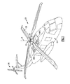
- FIG. 1 schematically illustrates an exemplary vertical takeoff and landing (VTOL) rotary-wing aircraft 20.
- the aircraft 20 in the disclosed, non-limiting embodiment includes a main rotor system 22 supported by an airframe 24 having an extending tail which mounts an anti-torque system 26 such as a tail rotor system.
- the main rotor assembly 22 is driven about an axis of rotation A through a main rotor gearbox MRG by one or more engines ENG.
- the main rotor gearbox MRG may be interposed between the one or more engines ENG, the main rotor system 22 and the anti-torque system 26.
- the main rotor gearbox MRG is mechanically connected to the main rotor system 22 and to the anti-torque system 26 so that the main rotor system 12 and the anti-torque system 16 may both driven by the main rotor gearbox MRG.
- the main rotor system 12 includes a multiple of rotor blades 28 mounted to a rotor hub 30.
- a particular helicopter configuration is illustrated and described in the disclosed embodiment, other configurations and/or machines, such as high speed compound rotary wing aircraft with supplemental translational thrust systems, dual contra-rotating, coaxial rotor system aircraft, turboprops, tilt-rotors and tilt-wing aircraft, will also benefit from the present invention.
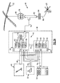
- a fly-by-wire type flight control system 40 includes a model following control system which shapes the pilot's controller and displacement commands through an inverse vehicle model to produce the desired aircraft response.
- the system 40 may, in one non-limiting embodiment include a Flight Control Computer (FCC) 38 ( Figure 2B ).
- the FCC 38 generally includes a Primary Flight Control System (PFCS) 42 and an Automatic Flight Augmentation and Cuing System (FACS) 44.
- PFCS 42 and FACS 44 execute explicit model following control laws to provide both control and stability augmentation.
- pilot commands are shaped directly into desired aircraft responses. These desired commands are then passed through an inverse aircraft model to obtain the control commands required to produce the desired response. The difference between the desired command and the aircraft response is also fed back to drive these errors towards zero, thus improving the model following performance.
- the PFCS 42 and FACS 44 each receive the force output command signals of a collective controller 46 on line 48, a cyclic controller 50 on line 52, and the aircraft's sensed parameter signals from sensors 54, on lines 56.
- the collective controller 46 and the cyclic controller 50 may take various forms including sidearm controllers, a yaw pedal system or other such flight controllers.
- the PFCS 42 and FACS 44 may each contain separate flight control laws for controlling the yaw, pitch, roll and lift axes of the aircraft.
- the logic is included in the PFCS and FACS control modules (schematically represented by blocks 62, 64, 66, 68 for the PFCS 42 and blocks 63, 65, 67, 69 for the FACS 44).
- the sensed parameter signals from aircraft sensors 54, on lines 56, provide the PFCS and FACS with the aircraft's angular rate and attitude response to the rotor command signals.
- the PFCS logic provides rotor command signals and the FACS logic provides conditioning and/or trimming of the PFCS four axis logic functions to provide, for example only, autopilot capabilities.
- the PFCS and FACS logic modules interconnect through bus 70 to provide rotor command signals on output lines 72 to a mixing function 74 which communicates commands on lines 76 for the displacement of the main rotor servos 78 and linkages 80 to control the tip path plane of the main rotor 22.
- a mixed command signal is also provided on line 82 to the tail rotor servos 84 to control the thrust of the anti-torque system 26 through linkages 86.
- a module 90 executes a collective trim actuator algorithm (CTA) 92.
- CTA collective trim actuator algorithm
- the functions of the algorithm 92 are disclosed in terms of functional block diagrams, and it should be understood by those skilled in the art with the benefit of this disclosure that these functions may be enacted in either dedicated hardware circuitry or programmed software routines capable of execution in a microprocessor based electronics control embodiment.
- the module 90 may be a portion of a flight control computer, a portion of a central vehicle control, an interactive vehicle dynamics module, a stand-alone line replaceable unit or other system.
- the non-limiting embodiment disclosed herein is applied to a collective system but could also be applied to any control axis depending on the type of system and any control inceptor such as a stick or pedal system.
- the module 90 typically includes a processor 94A, a memory 94B, and an interface 94C.
- the processor 94A may be any type of known microprocessor having desired performance characteristics.
- the memory 94B may, for example only, includes UVPROM, EEPROM, FLASH, RAM, ROM, DVD, CD, a hard drive, or other computer readable medium which stores the data and control algorithms described herein.
- the interface 94C facilitates communication with the FCC 38, as well as other avionics and systems.
- the module 90 communicates with a collective stick 100, the PFCS 42 and the FACS 44 to drive the main rotor servos 78.
- collective is controlled by a displacement type collective control stick whereas the cyclic and pedals are implemented by a force-sensing system.
- the cyclic and/or pedals may alternatively or additionally be implemented as displacement type controls as disclosed herein.
- the collective stick 100 operates as a generally closed system in terms of stick position. The current stick position is read in by the separate PFCS control laws 62, 64, 66, 68 and the main rotor servos 78 are commanded relative to the collective stick position.
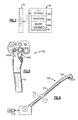
- the collective stick 100 includes a grip 102 ( Figure 5 ) mounted to an arm 104 driven by a motor 106 through a clutch 108.
- a sensor 110 such as a Rotary Variable Differential Transformer (RVDT) generates an output that is linearly proportional to the angular displacement D of the collective stick 100 ( Figure 6 ).
- the motor 106 and the clutch 108 are attached to the arm 102 at a point from which the travel of the collective stick 100 may be controlled.
- the motor 106 may be a rate command loop based device controlled through a rate feedback tachometer 112.
- the tachometer 112 may also be utilized to determine a run-away condition of the motor 106.
- the module 90, the motor 106, the clutch 108, the sensor 110 and the tachometer 112 may be provided as a spring-less motor-clutch electro-mechanical drive system 114 which supports the arm 104 within the aircraft cockpit.
- the algorithm 92 provides a feel approximation of a mechanical spring-biased collective system through the electro-mechanical drive system 114 such that the collective stick 100 provides a smooth, intuitive feel with a force feedback through the clutch 108 and the motor 106.
- the collective stick 100 also provides a subjective force ability via the clutch 108 so as to cue the pilot for events other than stick motion as will be further described below.
- the clutch 108 enables slippage in proportion to the system clutch engagement command. This way, the cueing force is more directly controllable by the CTA 92, avoids stored energy dissipation and jump problems, and enables a limited rate motor drive that does not require expensive and/or redundant system designs.
- the clutch 108 provides a variable slippage versus applied stick force controlled in proportion to the commanded clutch engagement from the CTA 92.
- the command is typically a current level that causes the torque transmitted through the clutch 108 to vary in proportion to the current level in the clutch circuit.
- the details of the clutch 108 itself are not the subject of invention, however, the method and procedures to control the clutch torque to provide effective force cues to the pilots are integral parts of the present invention and provided through the CTA 92.
- the module 90 communicates with the FACS 44 to drive the main rotor servos 78 through the PFCS 42.
- the FACS 44 typically includes a multiple of autopilot flight director modes 44A, such as, for example only, altitude hold, attitude hold, and hover hold.
- a low pass filter 44B communicates with the module 90 while a high pass filter 42C communicates with the PFCS 42.
- the filters 44B, 44C define, in part, rate limits communicated to the collective stick 100. For example only, should the FACS 44 generate a lift rate command above a speed capability of the motor 106 or other rate limit set by the filters 44B, 44C, the rate lift command is passed directly to the PFCS 44 without associated movement of the collective stick 100.
- the rate lift command from the FACS 44 will be input to the PFCS 42 without the pilot receiving a correspondingly sharp collective stick 100 movement.
- the FACS 44 should the FACS 44 generate a lift rate command below the speed capability of the motor 106 or other rate limit set by the filters 44B, 44C, the lift rate command will be communicated to the motor 106 such that the collective stick 100 moves in accords therewith. This facilitates a force feel approximation to the pilot such that the collective stick 100 provides a smooth, intuitive feel which facilitates operation in tactile feedback important flight profiles. That is, the module 90 generates a force cue, but not a rapid collective stick runaway.
- the motor 106 may accept rate commands from -10%/s to +10%/s where % defines the percent of collective stick travel.
- the clutch 108 engages the motor 106 to produce a desired frictional force to the collective stick 100.
- the motor 106 interacts with the clutch 108 such that some amount of clutch engagement is required for the motor 106 to move the collective stick 100.
- the friction felt at the collective stick 100 may be directly proportional to the amount of clutch command 108 engaged and, for example only, the clutch commands range from 0 to 100 percent.
- the grip 102 may include, in one-non-limiting embodiment, one or more discrete functional switches 102A, 102B ( Figure 5 ).
- a trim release 102A in one non-limiting embodiment, may be located under the grip 102 as a spring loaded trigger which is spring biased when not actuated outward. The trim release operates as a master switch for the motor 106 and the clutch 108 which forces the motor command 134 and clutch command 132 to zero.
- a multi-position switch (beeper) 102B in one non-limiting embodiment, may be located on the grip 102 to actuate or "beep" the collective stick up or down at a slow speed to slowly and accurately position the control stick for high fidelity lift control.
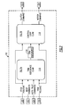
- the CTA 92 includes a trim reference control law 116 (also schematically illustrated in Figure 7A ) and a control loop control law 118 (also schematically illustrated in Figure 7B ).
- the trim reference control law 116 generates a trim reference for the collective stick position.
- the trim reference position is then utilized by the control loop control law 118 which drives the collective stick to the reference position while providing a force gradient in response to the stick distance displaced from the reference position.
- the trim reference control law 116 receives inputs such as a stick position 120, beep command 122, a FACS command 124, and a trim release command 126. It should be understood that alternative or additional inputs may be provided.
- the stick position 120 and the trim release command 126 are communicated in parallel to the control loop control law 118.
- a trim reference command 130 output from the trim reference control law 116 is also communicated to the control loop control law 118.
- the control loop control law 118 thereby generates a clutch command 132 to drive the clutch 108 and a motor command 134 to drive the motor 106.
- the trim reference control law 116 processes the beep commands 122 to drive an integrator 140.
- the limits into the integrator 140 may, in one-non-limiting embodiment, be modified to operate as soft stops for a force cueing capability which operates to cue the pilot for events other than stick motion, for example, flight envelope limits, environmental conditions, ground proximity, engine limits, stick shaking and the like through communication with the fly-by-wire flight control system.
- An adjustable beeper gain 142 determines, in percent per second (%/s), the rate of the integration.
- the integrator 140 is initialized (synchronized) to the current collective stick position when either trim release 102A is pressed or Auto Pilot reset 144 is requested.
- the FACS 44 commands are summed to the output of the integrator 140 to generate a reference position in percent for communication to the control loop control law 118.
- the trim reference control law 116 is controlled by the beeper switch 102B and provides a synchronized reference used by the FACS commands and the force limiting cues.
- the module 90 also provides soft stops by limiting the trim reference such that the pilot cannot move the collective stick outside the bounds of the soft stops as determined by the CTA 92.
- the soft stops may be used by functions such as engine limiting, vertical speed hold and other collective autopilot modes. Further uses of this soft stop capability are described hereafter.
- the soft stop or detent force may be commanded in variable levels according to cuing degree of effectiveness or severity of condition as well as indicator representative of the degree to which the pilot is resisting the cueing reference condition. Also, where the total force commanded to the collective stick may be the sum of cueing force components from various sources of position displacement from trim and proximity to any of several cueing reference values to include the logical selection or exclusion of any force component so as to prioritize the selected cueing reference.
- the control loop control law 118 drives the collective stick 100 to the reference position provided by the trim reference control law 116.
- the control loop control law 118 provides a position loop gain 146 tuned in accords with the bandwidth of module 90. For example, if the required bandwidth of the module is 10 Hz, the gain of the control loop 118 is set according to 2 ⁇ 10.
- the difference between the collective stick trim reference position and the current collective stick position also facilitates determination of the amount of clutch 108 that is applied to provide a force feel to the pilot ( Figure 7C ).
- two adjustable gains for the clutch 108 are provided.
- a bias clutch gain 148 determines how much force is required for the trim detent force component.
- the trim detent force component is intended as a set directional breakout force when the stick is moved in either direction from the trim reference stick position.
- a force gradient gain 150 provides a spring like force feedback component when the collective stick 100 is moved from the reference position ( Figure 7D ). These adjustable gains may be modified to the preference of the pilot.
- a closed loop control of the clutch 108 may be implemented to ensure that a desired torque can be produced for pilot force cueing.
- the gains of the position control loop and the clutch control loop may be scheduled to provide more effective force feel to the pilots.
- the position gain is scheduled through the use of position error as an auxiliary parameter for gain variation. If the error is large, meaning the pilot is pulling or pushing the stick far from the reference position, the gain is increased to make the motor respond faster, thus producing a more spring like force cueing to the pilots.
- FACS 44 flight modes when the collective stick is being commanded to control a lift mode of the aircraft, it is important to distinguish when the pilot intervenes with the FACS 44. This may be determined as a discrete that is calculated for the FACS 44 as the difference between the current stick position and the trim reference position. Although a force sensor could be used for this purpose, to indicate the force applied by the pilot, the present embodiment is intended to avoid the need for this device. Since the force applied to the collective stick by the CTA 92 is based on the displacement of the collective stick from the trim reference position, the determination of pilot intervention is sufficiently indicated by stick position relative to the reference position. The avoidance of a force sensing element is specifically possible in the cueing system described here.
- one advantage of the invention is that additional cueing forces can be directly commanded to the pilot by adding other cueing force components such as those based on load factor, engine performance, or other vehicle conditions.
- the determination of pilot intervention may involve more considerations than stick position compared to reference position.
- control loop control law 118 provides the force composed of the gradient gain 150 for a spring like force feedback when the collective stick 100 is moved from the reference position plus the bias clutch gain 148 which provides detent when trim release is not actuated.
- the spring force component provides a smoothly varying force as the collective stick is moved away from the trim reference for pilot-in-the-loop flight.
- the detent force component provides a positive trim reference position hold primarily for the FACS control of the collective stick position for automatic control modes.
- cueing force components can be commanded related to stick positional damping, or other vehicle conditions. While the CTA 92 commands these primary force cueing commands, the CTA 92 also provides smooth transition of cueing functions so as not to result in discontinuities perceived by the pilot.
- the CTA 92 in hands-off operation provides positioning loop closure of the collective stick position to maintain the stick at the reference position, such as when the reference position is under automatic control by the FACS.
- the collective stick is under automatic FACS control it is important that the stick follow the commanded position precisely. This is accomplished by the trim motor 106 positioning loop closure together with the detent force component which is designed to be sufficient to overcome physical forces opposing motion such as friction and unbalanced stick weight, while also not supplying overly large breakout forces to the pilot-in-the-loop operation.
- the pilot operates the collective controller 46 to change the collective blade angles that essentially control the vertical rate of the aircraft.
- the collective stick 100 must provide accurate cues to the pilot in terms of force feedback.
- the collective stick 100 is initialized at a current collective position to record the current position as the trim reference position.
- the trim reference may change if trim release is engaged, the reference is "beeped" by using the trim switch 102B, or the FACS 42 is commanding the flight control system.
- the drive system 114 reacts with a force proportional to the displacement of the collective stick 100. That is, the motor 106 is commanded to drive the collective stick 100 back toward the trim reference position.
- the drive system 114 facilities Fly-By-Wire flight control to cue the pilots.
- the pilots are provided with a spring-like feel indicative of collective stick 100 displacement from the trim reference position. No force sensors are required as the force feedback is determined and provided with only the collective stick position sensor 112, the motor 106 and the clutch 108.
- the collective controller 46 through communication with the FACS 42, facilitates force cueing to the pilots through soft stops which may indicate various events other than stick motion.
- the collective trim force capability can be used to cue the pilot as to flight envelope limits, environmental conditions, ground proximity, engine limits, brownouts, DVE (Degraded Visual Environment) operations and the like.
- a soft stop type force can be commanded in the down direction by applying a clutch engage force level and movement of the trim reference, or a secondary component may be summed to the nominal reference, in the down direction. That way, the pilot must resist the force level of the clutch in order to overpower the down cueing command.
- the pilot When or if the pilot relaxes and the stick moves down the commanded amount, the pilot will perceive the force subside as the desired response occurs to satisfy the cueing objective i.e. alleviate operating near the engine limit.
- the magnitude of the cueing force can be modulated in response to severity and priority of the condition by modulating the clutch engagement command in proportion to the desired cue force.
- the mathematical equation for the soft stop cue force may also be modulated so as to define a gradient relative to the intended cue reference such that a relatively small force is encountered initially then builds as proximity to the limit value is neared.
- This type of cueing is accomplished without need for a force sensing device because the force applied to the collective stick is controlled by, and is in proportion to, the degree of commanded clutch engagement in the direction to resist the speed the motor is commanded to move.
- Force cuing and the ability to provide soft stops have many implications for reducing pilot workload in a high work load environment because stick force cuing supplements, or removes reliance upon, the need for the pilot to closely monitor secondary display cues within the cockpit such as torque or collective position indicators.
- the stick force cueing provides a measure of indication that reduces the need for continuous and direct monitoring of the cockpit displays and enables the pilot to concentrate proportionately more on higher level mission tasks, or proportionately enable more "eyes out of the cockpit" concentration.
- the collective controller 46 provides superior weight savings, advanced pilot cuing, reduced component failure criticality, and higher reliability than active sticks and other conventional full authority force cueing systems (such as FAS) because potential actuator runaway conditions are determined by intrinsic equipment characteristics (maximum motor speed) and so are readily controlled.
- FAS provides a directly commandable force, but requires a full authority and high rate hydraulic force actuation subsystem that in turn requires fault criticality considerations in the system design.
- the collective controller 46 also accomplishes these tasks without any sort of force sensor yet still provides a true spring like force approximation.
- the collective controller 46 avoids the energy dissipation jump problem and enables generalized force cueing capability.
- the collective controller 46 also permits direct, specific, and large force cues to be applied while the failure mode can be limited to a benign maximum runaway motor speed that is within conventional inherently limited criteria. This way, flight criticality can be reduced or avoided in the control law software and hardware design.
Landscapes
- Engineering & Computer Science (AREA)
- Aviation & Aerospace Engineering (AREA)
- Automation & Control Theory (AREA)
- Physics & Mathematics (AREA)
- Radar, Positioning & Navigation (AREA)
- Remote Sensing (AREA)
- Mechanical Engineering (AREA)
- General Physics & Mathematics (AREA)
- Hydraulic Clutches, Magnetic Clutches, Fluid Clutches, And Fluid Joints (AREA)
- Mechanical Control Devices (AREA)
- Transmission Devices (AREA)
- Toys (AREA)
- Control Of Position, Course, Altitude, Or Attitude Of Moving Bodies (AREA)
Applications Claiming Priority (1)
| Application Number | Priority Date | Filing Date | Title |
|---|---|---|---|
| US12/060,119 US8271151B2 (en) | 2008-03-31 | 2008-03-31 | Flight control system for rotary wing aircraft |
Publications (3)
| Publication Number | Publication Date |
|---|---|
| EP2107002A2 true EP2107002A2 (de) | 2009-10-07 |
| EP2107002A3 EP2107002A3 (de) | 2015-10-28 |
| EP2107002B1 EP2107002B1 (de) | 2018-05-02 |
Family
ID=40790715
Family Applications (1)
| Application Number | Title | Priority Date | Filing Date |
|---|---|---|---|
| EP08020436.5A Active EP2107002B1 (de) | 2008-03-31 | 2008-11-25 | Kollektives Flugregelsystem für Drehflügler |
Country Status (2)
| Country | Link |
|---|---|
| US (1) | US8271151B2 (de) |
| EP (1) | EP2107002B1 (de) |
Cited By (5)
| Publication number | Priority date | Publication date | Assignee | Title |
|---|---|---|---|---|
| US9304516B2 (en) | 2011-01-14 | 2016-04-05 | Textron Innovations Inc. | Flight control laws for vertical flight path |
| EP3297912A4 (de) * | 2015-05-21 | 2019-01-16 | Merlin Technology Inc. | Verbesserter kollektiver aktuator für notfälle mit reibungsabzug und verfahren für einen hubschrauber |
| EP3492373A1 (de) * | 2017-11-30 | 2019-06-05 | Bell Helicopter Textron Inc. | System und verfahren zur flugmodusanzeige |
| EP3186146B1 (de) | 2014-08-28 | 2019-10-09 | Sikorsky Aircraft Corporation | Anstellwinkelsteuerungssystem |
| FR3130252A1 (fr) * | 2021-12-10 | 2023-06-16 | Safran Electronics & Defense | Compensateur de vol pour aéronef |
Families Citing this family (43)
| Publication number | Priority date | Publication date | Assignee | Title |
|---|---|---|---|---|
| US9156546B2 (en) * | 2008-03-11 | 2015-10-13 | The Boeing Company | Active-inceptor tactile-cueing hands-off rate-limit |
| EP2296064B1 (de) * | 2009-09-10 | 2019-04-24 | Sikorsky Aircraft Corporation | Leben verbesserndes Flugsteuerungssystem |
| FR2959837B1 (fr) * | 2010-05-07 | 2012-05-04 | Eurocopter France | Systeme de commandes de vol simplifiees comportant un dispositif de friction debrayable |
| DE102010035825A1 (de) * | 2010-08-30 | 2012-03-01 | Liebherr-Aerospace Lindenberg Gmbh | Steuerorgansystem und Vorrichtung zur Erzeugung eines virtuellen Echtzeitmodells |
| FR2977948B1 (fr) * | 2011-07-12 | 2014-11-07 | Eurocopter France | Procede de pilotage automatique d'un aeronef a voilure tournante comprenant au moins une helice propulsive, dispositif de pilotage automatique et aeronef |
| US8718841B2 (en) * | 2012-02-14 | 2014-05-06 | Sikorsky Aircraft Corporation | Method and system for providing sideslip envelope protection |
| US9266604B2 (en) * | 2012-07-17 | 2016-02-23 | Mason Electric Company | Complex-dynamic air and ground vehicle control inceptor |
| US9026274B2 (en) * | 2012-08-31 | 2015-05-05 | Sikorsky Aircraft Corporation | Method of controlling an electric propulsion system |
| USD705407S1 (en) * | 2012-12-20 | 2014-05-20 | David O. Edmonds | Ceiling fan |
| FR3012112B1 (fr) * | 2013-10-22 | 2017-04-21 | Ratier Figeac Soc | Procede de surveillance de fonctionnement d'un dispositif de pilotage d'aeronef et dispositif de pilotage d'aeronef ainsi surveille |
| RU2539708C1 (ru) * | 2013-12-30 | 2015-01-27 | Открытое акционерное общество "Камов" | Командно-пилотажный индикатор вертолета |
| US9366546B2 (en) | 2014-02-24 | 2016-06-14 | Lockheed Martin Corporation | Projected synthetic vision |
| US9563276B2 (en) * | 2014-03-26 | 2017-02-07 | Lockheed Martin Corporation | Tactile and peripheral vision combined modality hover drift cueing |
| US9908614B2 (en) * | 2014-05-02 | 2018-03-06 | Sikorsky Aircraft Corporation | Crew seat integral inceptor system for aircraft |
| US9868522B2 (en) * | 2014-08-21 | 2018-01-16 | Bell Helicopter Textron Inc. | Rotorcraft autopilot control |
| EP3186147A4 (de) | 2014-08-28 | 2018-04-25 | Sikorsky Aircraft Corporation | Anstellwinkelsteuerungssystem |
| WO2016039834A2 (en) * | 2014-08-29 | 2016-03-17 | Sikorsky Aircraft Corporation | Vector limiting of a rotor control volume |
| US20170267338A1 (en) | 2014-10-01 | 2017-09-21 | Sikorsky Aircraft Corporation | Acoustic signature variation of aircraft utilizing a clutch |
| EP3201077B1 (de) | 2014-10-01 | 2020-05-20 | Sikorsky Aircraft Corporation | Doppelrotor, drehflügelflugzeug |
| US11299257B2 (en) * | 2014-10-13 | 2022-04-12 | Gulfstream Aerospace Corporation | Aircraft, systems, and methods for trim control in fly-by-wire aircraft systems |
| PL3069990T3 (pl) * | 2015-03-20 | 2017-06-30 | Airbus Helicopters Deutschland GmbH | Urządzenie generujące sztuczne odczucie siły, do systemu sterowania pojazdu, a zwłaszcza statku powietrznego |
| KR101750782B1 (ko) * | 2015-04-23 | 2017-06-27 | 한국항공우주산업 주식회사 | Fbw 비행제어시스템에서 사용되는 능동형 조종입력시스템 |
| US10618645B2 (en) * | 2015-08-25 | 2020-04-14 | Aerovironment, Inc. | Ganged servo flight control system for an unmanned aerial vehicle |
| US9715234B2 (en) * | 2015-11-30 | 2017-07-25 | Metal Industries Research & Development Centre | Multiple rotors aircraft and control method |
| US10618635B2 (en) * | 2016-01-13 | 2020-04-14 | Sikorsky Aircraft Corporation | Pilot activated trim for fly-by-wire aircraft |
| WO2018064209A1 (en) | 2016-09-28 | 2018-04-05 | Kitty Hawk Corporation | Tilt-wing aircraft |
| US10189559B2 (en) * | 2016-11-22 | 2019-01-29 | Sikorsky Aircraft Corporation | Rotor speed control using a feed-forward rotor speed command |
| US10604268B2 (en) * | 2017-02-22 | 2020-03-31 | Pratt & Whitney Canada Corp. | Autothrottle control for turboprop engines |
| US10802482B2 (en) | 2017-02-27 | 2020-10-13 | Textron Innovations Inc. | Reverse tactile cue for rotorcraft rotor overspeed protection |
| US10261517B2 (en) * | 2017-04-11 | 2019-04-16 | Bell Helicopter Textron Inc. | Default in-detent vertical speed/altitude hold |
| US10633104B2 (en) | 2017-05-17 | 2020-04-28 | General Electric Company | Hybrid-electric propulsion system for an aircraft |
| US10800536B2 (en) | 2017-06-09 | 2020-10-13 | General Electric Company | Propulsion system for an aircraft |
| US10006375B1 (en) | 2017-07-11 | 2018-06-26 | General Electric Company | Propulsion system for an aircraft |
| US11117653B2 (en) * | 2017-11-28 | 2021-09-14 | Textron Innovations Inc. | System and method for tactile cueing through rotorcraft pilot controls using variable friction and force gradient |
| US10816971B2 (en) * | 2018-02-12 | 2020-10-27 | Textron Innovations Inc. | Autopilot recoupling for rotorcraft |
| US11312480B2 (en) | 2018-06-01 | 2022-04-26 | Textron Innovations Inc. | System and method for controlling rotorcraft |
| US10816999B2 (en) * | 2018-06-01 | 2020-10-27 | Textron Innovations Inc. | System and method for controlling rotorcraft |
| US20200023955A1 (en) * | 2018-07-23 | 2020-01-23 | Textron Innovations Inc. | System and Method for Rotorcraft Flight Control |
| CN109592064B (zh) * | 2018-11-02 | 2022-04-19 | 中国航空工业集团公司西安飞机设计研究所 | 飞机与机械操纵系统变形差异对机动操纵影响设计方法 |
| US11591074B1 (en) * | 2018-11-28 | 2023-02-28 | Zunum Aero, Inc. | System and methods for designing and building regional hybrid-to-electric systems and methods for designing and optimizing regional hybrid-to-electric aircraft |
| FR3093320B1 (fr) * | 2019-02-28 | 2021-01-29 | Airbus Helicopters | Mécanisme d’alerte haptique d’un pilote d’aéronef et aéronef. |
| EP3998198B1 (de) | 2021-02-19 | 2024-07-03 | Lilium eAircraft GmbH | Flugzeugsteuerorganvorrichtung und flugsteuerungssystem eines flugzeugs |
| US12480449B2 (en) | 2022-08-22 | 2025-11-25 | General Electric Company | Propulsion system including an electric machine for starting a gas turbine engine |
Family Cites Families (22)
| Publication number | Priority date | Publication date | Assignee | Title |
|---|---|---|---|---|
| US4626998A (en) * | 1983-05-02 | 1986-12-02 | United Technologies Corporation | Heading reference trim system |
| US4770375A (en) | 1986-07-24 | 1988-09-13 | United Technologies Corporation | Collective stick force-check device |
| US4696445A (en) | 1986-09-18 | 1987-09-29 | United Technologies Corporation | Collective control system for a helicopter |
| US4924400A (en) | 1988-09-01 | 1990-05-08 | United Technologies Corporation | Arrangement for controlling the performance of bob-up/bob-down maneuvers by a helicopter |
| US5076517A (en) | 1989-08-14 | 1991-12-31 | United Technologies Corporation | Programmable, linear collective control system for a helicopter |
| US5156363A (en) | 1991-02-28 | 1992-10-20 | United Technologies Corporation | Helicopter collective stick of the displacement type occupying a minimum space envelope yet whose grip generates an arc of large radius |
| WO1993005457A1 (en) | 1991-08-28 | 1993-03-18 | United Technologies Corporation | Vertical control system for rotary wing aircraft |
| US5553812A (en) | 1994-06-03 | 1996-09-10 | United Technologies Corporation | Inertial velocity command system |
| FR2728537A1 (fr) * | 1994-12-21 | 1996-06-28 | Eurocopter France | Dispositif pour l'actionnement d'un organe commande pour un aeronef, tel que notamment un helicoptere, a commandes de vol electriques |
| US5853152A (en) * | 1997-04-29 | 1998-12-29 | Sikorsky Aircraft Corporation | Collective detent system for vertical takeoff flight operations |
| FR2766158B1 (fr) | 1997-07-18 | 1999-10-01 | Bonnans Sa | Procede et dispositif d'aide au controle, par le pilote, des limitations de puissance du ou des turbomoteurs et/ou du regime rotor des helicopteres thermopropulses |
| FR2769285B1 (fr) | 1997-10-07 | 1999-12-03 | Eurocopter France | Dispositif de commande d'un systeme anticouple mixte d'un helicoptere |
| US6012676A (en) | 1998-03-31 | 2000-01-11 | Sikorsky Aircraft Corporation | Integrated fire and flight control system with automatic engine torque limiting |
| US6145428A (en) | 1998-03-31 | 2000-11-14 | Sikorsky Aircraft Corporation | Integrated fire and flight control system for controlling the angle of attack of a rotary wing aircraft |
| US6325331B1 (en) * | 1998-12-11 | 2001-12-04 | Bell Helicopter Textron Inc. | Trim actuator |
| US6695264B2 (en) | 2000-05-16 | 2004-02-24 | Bell Helicopter Textron, Inc. | Power lever tactile cueing system |
| WO2003040844A2 (en) * | 2001-11-06 | 2003-05-15 | Bombardier Inc. | Apparatus for controlling a joystick having force-feedback |
| US6648269B2 (en) | 2001-12-10 | 2003-11-18 | Sikorsky Aircraft Corporation | Trim augmentation system for a rotary wing aircraft |
| EP1485892B1 (de) | 2002-03-21 | 2012-10-17 | Bell Helicopter Textron Inc. | Verfahren und vorrichtung zur tacktauslösung von flugzeugsteuerelementen |
| US6679458B2 (en) * | 2002-06-10 | 2004-01-20 | The Boeing Company | Split detent tactile cueing vehicle control system |
| US7126496B2 (en) | 2004-09-30 | 2006-10-24 | Safe Flight Instrument Corporation | Tactile cueing system and method for aiding a helicopter pilot in making landings |
| US7930074B2 (en) * | 2007-03-19 | 2011-04-19 | Sikorsky Aircraft Corporation | Vertical speed and flight path command module for displacement collective utilizing tactile cueing and tactile feedback |
-
2008
- 2008-03-31 US US12/060,119 patent/US8271151B2/en not_active Expired - Fee Related
- 2008-11-25 EP EP08020436.5A patent/EP2107002B1/de active Active
Cited By (8)
| Publication number | Priority date | Publication date | Assignee | Title |
|---|---|---|---|---|
| US9304516B2 (en) | 2011-01-14 | 2016-04-05 | Textron Innovations Inc. | Flight control laws for vertical flight path |
| EP3186146B1 (de) | 2014-08-28 | 2019-10-09 | Sikorsky Aircraft Corporation | Anstellwinkelsteuerungssystem |
| EP3297912A4 (de) * | 2015-05-21 | 2019-01-16 | Merlin Technology Inc. | Verbesserter kollektiver aktuator für notfälle mit reibungsabzug und verfahren für einen hubschrauber |
| US11820498B2 (en) | 2015-05-21 | 2023-11-21 | Merlin Technology, Inc. | Advanced emergency collective actuator with friction pull-off and method for a helicopter |
| US12509223B2 (en) | 2015-05-21 | 2025-12-30 | Merlin Technology, Inc. | Advanced emergency collective actuator with friction pull-off and method for a helicopter |
| EP3492373A1 (de) * | 2017-11-30 | 2019-06-05 | Bell Helicopter Textron Inc. | System und verfahren zur flugmodusanzeige |
| US11136136B2 (en) | 2017-11-30 | 2021-10-05 | Textron Innovations Inc. | System and method for flight mode annunciation |
| FR3130252A1 (fr) * | 2021-12-10 | 2023-06-16 | Safran Electronics & Defense | Compensateur de vol pour aéronef |
Also Published As
| Publication number | Publication date |
|---|---|
| EP2107002B1 (de) | 2018-05-02 |
| US8271151B2 (en) | 2012-09-18 |
| US20120072056A1 (en) | 2012-03-22 |
| EP2107002A3 (de) | 2015-10-28 |
Similar Documents
| Publication | Publication Date | Title |
|---|---|---|
| US8271151B2 (en) | Flight control system for rotary wing aircraft | |
| EP3620373B1 (de) | Verklemmten detent-monitore für kollektive und zyklische sticks | |
| US11599111B2 (en) | Reverse tactile cue for rotorcraft rotor overspeed protection | |
| US11117653B2 (en) | System and method for tactile cueing through rotorcraft pilot controls using variable friction and force gradient | |
| CN110127041B (zh) | 用于旋翼飞行器自旋进入辅助的系统和方法 | |
| US5489830A (en) | Control system with loadfeel and backdrive | |
| US10577083B2 (en) | Method of controlling an artificial force feel generating device for generation of an artificial feeling of force on an inceptor of a vehicle control system | |
| EP2261116B1 (de) | Automatisches Trimmsystem für Fly-by-Wire-Flugzeuge mit einmaligen Trimmsteuerungen | |
| US9868513B2 (en) | Device for warning a rotorcraft pilot by means of tactile signals and making use of a trim actuator connected to a flight control member | |
| US12162616B2 (en) | Pilot interface for aircraft autothrottle control | |
| CN109407685B (zh) | 用于旋翼飞行器总距动力保持的系统和方法 | |
| CN108536159A (zh) | 旋翼飞行器控制模式转换平滑 | |
| EP2810872B1 (de) | System und Verfahren zur Maximierung der sicheren Flugzeuglandefähigkeit während des Betriebs mit einem betriebsunfähigen Motor | |
| EP3489134B1 (de) | System und verfahren zur pilot-in-control-steuerung in einem drehflügelflugzeug | |
| EP3569497A1 (de) | System und verfahren zur taktilen signalisierung durch drehflügler-pilotensteuerungen mit einem variablen reibungs- und kraftgradienten | |
| EP3456627A1 (de) | System und verfahren zur erkennung der heckrotorspanne | |
| EP3388335B1 (de) | Standardmässiges verriegeltes halten der vertikalen geschwindigkeit und der höhe | |
| EP3575914B1 (de) | Vorrichtung und verfahren für einen automatisierten flugmodus vom sinkflug zum schwebeflug | |
| EP4310007A1 (de) | Fehlermonitor für kollektiven und zyklischen steuerknüppel |
Legal Events
| Date | Code | Title | Description |
|---|---|---|---|
| PUAI | Public reference made under article 153(3) epc to a published international application that has entered the european phase |
Free format text: ORIGINAL CODE: 0009012 |
|
| AK | Designated contracting states |
Kind code of ref document: A2 Designated state(s): AT BE BG CH CY CZ DE DK EE ES FI FR GB GR HR HU IE IS IT LI LT LU LV MC MT NL NO PL PT RO SE SI SK TR |
|
| AX | Request for extension of the european patent |
Extension state: AL BA MK RS |
|
| PUAL | Search report despatched |
Free format text: ORIGINAL CODE: 0009013 |
|
| AK | Designated contracting states |
Kind code of ref document: A3 Designated state(s): AT BE BG CH CY CZ DE DK EE ES FI FR GB GR HR HU IE IS IT LI LT LU LV MC MT NL NO PL PT RO SE SI SK TR |
|
| AX | Request for extension of the european patent |
Extension state: AL BA MK RS |
|
| RIC1 | Information provided on ipc code assigned before grant |
Ipc: B64C 13/00 20060101AFI20150922BHEP Ipc: B64C 13/50 20060101ALI20150922BHEP Ipc: B64C 27/54 20060101ALI20150922BHEP |
|
| 17P | Request for examination filed |
Effective date: 20160404 |
|
| RBV | Designated contracting states (corrected) |
Designated state(s): AT BE BG CH CY CZ DE DK EE ES FI FR GB GR HR HU IE IS IT LI LT LU LV MC MT NL NO PL PT RO SE SI SK TR |
|
| AKX | Designation fees paid |
Designated state(s): AT BE BG CH CY CZ DE DK EE ES FI FR GB GR HR HU IE IS IT LI LT LU LV MC MT NL NO PL PT RO SE SI SK TR |
|
| AXX | Extension fees paid |
Extension state: MK Extension state: AL Extension state: RS Extension state: BA |
|
| 17Q | First examination report despatched |
Effective date: 20170208 |
|
| RIC1 | Information provided on ipc code assigned before grant |
Ipc: B64C 13/50 20060101ALI20170928BHEP Ipc: B64C 27/54 20060101ALI20170928BHEP Ipc: G05D 1/08 20060101ALI20170928BHEP Ipc: B64C 13/00 20060101AFI20170928BHEP |
|
| GRAP | Despatch of communication of intention to grant a patent |
Free format text: ORIGINAL CODE: EPIDOSNIGR1 |
|
| INTG | Intention to grant announced |
Effective date: 20171130 |
|
| GRAS | Grant fee paid |
Free format text: ORIGINAL CODE: EPIDOSNIGR3 |
|
| GRAA | (expected) grant |
Free format text: ORIGINAL CODE: 0009210 |
|
| AK | Designated contracting states |
Kind code of ref document: B1 Designated state(s): AT BE BG CH CY CZ DE DK EE ES FI FR GB GR HR HU IE IS IT LI LT LU LV MC MT NL NO PL PT RO SE SI SK TR |
|
| REG | Reference to a national code |
Ref country code: GB Ref legal event code: FG4D |
|
| REG | Reference to a national code |
Ref country code: CH Ref legal event code: EP Ref country code: AT Ref legal event code: REF Ref document number: 994942 Country of ref document: AT Kind code of ref document: T Effective date: 20180515 |
|
| REG | Reference to a national code |
Ref country code: DE Ref legal event code: R096 Ref document number: 602008055068 Country of ref document: DE Ref country code: IE Ref legal event code: FG4D |
|
| REG | Reference to a national code |
Ref country code: NL Ref legal event code: MP Effective date: 20180502 |
|
| REG | Reference to a national code |
Ref country code: LT Ref legal event code: MG4D |
|
| PG25 | Lapsed in a contracting state [announced via postgrant information from national office to epo] |
Ref country code: ES Free format text: LAPSE BECAUSE OF FAILURE TO SUBMIT A TRANSLATION OF THE DESCRIPTION OR TO PAY THE FEE WITHIN THE PRESCRIBED TIME-LIMIT Effective date: 20180502 Ref country code: LT Free format text: LAPSE BECAUSE OF FAILURE TO SUBMIT A TRANSLATION OF THE DESCRIPTION OR TO PAY THE FEE WITHIN THE PRESCRIBED TIME-LIMIT Effective date: 20180502 Ref country code: SE Free format text: LAPSE BECAUSE OF FAILURE TO SUBMIT A TRANSLATION OF THE DESCRIPTION OR TO PAY THE FEE WITHIN THE PRESCRIBED TIME-LIMIT Effective date: 20180502 Ref country code: NO Free format text: LAPSE BECAUSE OF FAILURE TO SUBMIT A TRANSLATION OF THE DESCRIPTION OR TO PAY THE FEE WITHIN THE PRESCRIBED TIME-LIMIT Effective date: 20180802 Ref country code: BG Free format text: LAPSE BECAUSE OF FAILURE TO SUBMIT A TRANSLATION OF THE DESCRIPTION OR TO PAY THE FEE WITHIN THE PRESCRIBED TIME-LIMIT Effective date: 20180802 Ref country code: FI Free format text: LAPSE BECAUSE OF FAILURE TO SUBMIT A TRANSLATION OF THE DESCRIPTION OR TO PAY THE FEE WITHIN THE PRESCRIBED TIME-LIMIT Effective date: 20180502 |
|
| PG25 | Lapsed in a contracting state [announced via postgrant information from national office to epo] |
Ref country code: HR Free format text: LAPSE BECAUSE OF FAILURE TO SUBMIT A TRANSLATION OF THE DESCRIPTION OR TO PAY THE FEE WITHIN THE PRESCRIBED TIME-LIMIT Effective date: 20180502 Ref country code: GR Free format text: LAPSE BECAUSE OF FAILURE TO SUBMIT A TRANSLATION OF THE DESCRIPTION OR TO PAY THE FEE WITHIN THE PRESCRIBED TIME-LIMIT Effective date: 20180803 Ref country code: LV Free format text: LAPSE BECAUSE OF FAILURE TO SUBMIT A TRANSLATION OF THE DESCRIPTION OR TO PAY THE FEE WITHIN THE PRESCRIBED TIME-LIMIT Effective date: 20180502 Ref country code: NL Free format text: LAPSE BECAUSE OF FAILURE TO SUBMIT A TRANSLATION OF THE DESCRIPTION OR TO PAY THE FEE WITHIN THE PRESCRIBED TIME-LIMIT Effective date: 20180502 |
|
| REG | Reference to a national code |
Ref country code: AT Ref legal event code: MK05 Ref document number: 994942 Country of ref document: AT Kind code of ref document: T Effective date: 20180502 |
|
| PG25 | Lapsed in a contracting state [announced via postgrant information from national office to epo] |
Ref country code: PT Free format text: LAPSE BECAUSE OF FAILURE TO SUBMIT A TRANSLATION OF THE DESCRIPTION OR TO PAY THE FEE WITHIN THE PRESCRIBED TIME-LIMIT Effective date: 20180903 |
|
| PG25 | Lapsed in a contracting state [announced via postgrant information from national office to epo] |
Ref country code: PL Free format text: LAPSE BECAUSE OF FAILURE TO SUBMIT A TRANSLATION OF THE DESCRIPTION OR TO PAY THE FEE WITHIN THE PRESCRIBED TIME-LIMIT Effective date: 20180502 Ref country code: SK Free format text: LAPSE BECAUSE OF FAILURE TO SUBMIT A TRANSLATION OF THE DESCRIPTION OR TO PAY THE FEE WITHIN THE PRESCRIBED TIME-LIMIT Effective date: 20180502 Ref country code: AT Free format text: LAPSE BECAUSE OF FAILURE TO SUBMIT A TRANSLATION OF THE DESCRIPTION OR TO PAY THE FEE WITHIN THE PRESCRIBED TIME-LIMIT Effective date: 20180502 Ref country code: DK Free format text: LAPSE BECAUSE OF FAILURE TO SUBMIT A TRANSLATION OF THE DESCRIPTION OR TO PAY THE FEE WITHIN THE PRESCRIBED TIME-LIMIT Effective date: 20180502 Ref country code: EE Free format text: LAPSE BECAUSE OF FAILURE TO SUBMIT A TRANSLATION OF THE DESCRIPTION OR TO PAY THE FEE WITHIN THE PRESCRIBED TIME-LIMIT Effective date: 20180502 Ref country code: CZ Free format text: LAPSE BECAUSE OF FAILURE TO SUBMIT A TRANSLATION OF THE DESCRIPTION OR TO PAY THE FEE WITHIN THE PRESCRIBED TIME-LIMIT Effective date: 20180502 Ref country code: RO Free format text: LAPSE BECAUSE OF FAILURE TO SUBMIT A TRANSLATION OF THE DESCRIPTION OR TO PAY THE FEE WITHIN THE PRESCRIBED TIME-LIMIT Effective date: 20180502 |
|
| REG | Reference to a national code |
Ref country code: DE Ref legal event code: R097 Ref document number: 602008055068 Country of ref document: DE |
|
| PLBE | No opposition filed within time limit |
Free format text: ORIGINAL CODE: 0009261 |
|
| STAA | Information on the status of an ep patent application or granted ep patent |
Free format text: STATUS: NO OPPOSITION FILED WITHIN TIME LIMIT |
|
| 26N | No opposition filed |
Effective date: 20190205 |
|
| PG25 | Lapsed in a contracting state [announced via postgrant information from national office to epo] |
Ref country code: SI Free format text: LAPSE BECAUSE OF FAILURE TO SUBMIT A TRANSLATION OF THE DESCRIPTION OR TO PAY THE FEE WITHIN THE PRESCRIBED TIME-LIMIT Effective date: 20180502 |
|
| REG | Reference to a national code |
Ref country code: CH Ref legal event code: PL |
|
| PG25 | Lapsed in a contracting state [announced via postgrant information from national office to epo] |
Ref country code: MC Free format text: LAPSE BECAUSE OF FAILURE TO SUBMIT A TRANSLATION OF THE DESCRIPTION OR TO PAY THE FEE WITHIN THE PRESCRIBED TIME-LIMIT Effective date: 20180502 Ref country code: LU Free format text: LAPSE BECAUSE OF NON-PAYMENT OF DUE FEES Effective date: 20181125 |
|
| REG | Reference to a national code |
Ref country code: BE Ref legal event code: MM Effective date: 20181130 |
|
| REG | Reference to a national code |
Ref country code: IE Ref legal event code: MM4A |
|
| PG25 | Lapsed in a contracting state [announced via postgrant information from national office to epo] |
Ref country code: CH Free format text: LAPSE BECAUSE OF NON-PAYMENT OF DUE FEES Effective date: 20181130 Ref country code: LI Free format text: LAPSE BECAUSE OF NON-PAYMENT OF DUE FEES Effective date: 20181130 |
|
| PG25 | Lapsed in a contracting state [announced via postgrant information from national office to epo] |
Ref country code: IE Free format text: LAPSE BECAUSE OF NON-PAYMENT OF DUE FEES Effective date: 20181125 |
|
| PG25 | Lapsed in a contracting state [announced via postgrant information from national office to epo] |
Ref country code: BE Free format text: LAPSE BECAUSE OF NON-PAYMENT OF DUE FEES Effective date: 20181130 |
|
| PG25 | Lapsed in a contracting state [announced via postgrant information from national office to epo] |
Ref country code: MT Free format text: LAPSE BECAUSE OF NON-PAYMENT OF DUE FEES Effective date: 20181125 |
|
| PG25 | Lapsed in a contracting state [announced via postgrant information from national office to epo] |
Ref country code: TR Free format text: LAPSE BECAUSE OF FAILURE TO SUBMIT A TRANSLATION OF THE DESCRIPTION OR TO PAY THE FEE WITHIN THE PRESCRIBED TIME-LIMIT Effective date: 20180502 |
|
| PG25 | Lapsed in a contracting state [announced via postgrant information from national office to epo] |
Ref country code: CY Free format text: LAPSE BECAUSE OF FAILURE TO SUBMIT A TRANSLATION OF THE DESCRIPTION OR TO PAY THE FEE WITHIN THE PRESCRIBED TIME-LIMIT Effective date: 20180502 Ref country code: HU Free format text: LAPSE BECAUSE OF FAILURE TO SUBMIT A TRANSLATION OF THE DESCRIPTION OR TO PAY THE FEE WITHIN THE PRESCRIBED TIME-LIMIT; INVALID AB INITIO Effective date: 20081125 |
|
| PG25 | Lapsed in a contracting state [announced via postgrant information from national office to epo] |
Ref country code: IS Free format text: LAPSE BECAUSE OF FAILURE TO SUBMIT A TRANSLATION OF THE DESCRIPTION OR TO PAY THE FEE WITHIN THE PRESCRIBED TIME-LIMIT Effective date: 20180902 |
|
| P01 | Opt-out of the competence of the unified patent court (upc) registered |
Effective date: 20230518 |
|
| PGFP | Annual fee paid to national office [announced via postgrant information from national office to epo] |
Ref country code: DE Payment date: 20241127 Year of fee payment: 17 |
|
| PGFP | Annual fee paid to national office [announced via postgrant information from national office to epo] |
Ref country code: GB Payment date: 20241127 Year of fee payment: 17 |
|
| PGFP | Annual fee paid to national office [announced via postgrant information from national office to epo] |
Ref country code: FR Payment date: 20241128 Year of fee payment: 17 |
|
| PGFP | Annual fee paid to national office [announced via postgrant information from national office to epo] |
Ref country code: IT Payment date: 20241122 Year of fee payment: 17 |