EP2107142A2 - Procédé de fonctionnement d'une machine à filer - Google Patents
Procédé de fonctionnement d'une machine à filer Download PDFInfo
- Publication number
- EP2107142A2 EP2107142A2 EP09000988A EP09000988A EP2107142A2 EP 2107142 A2 EP2107142 A2 EP 2107142A2 EP 09000988 A EP09000988 A EP 09000988A EP 09000988 A EP09000988 A EP 09000988A EP 2107142 A2 EP2107142 A2 EP 2107142A2
- Authority
- EP
- European Patent Office
- Prior art keywords
- machine
- yarn processing
- unit
- sensors
- maintenance
- Prior art date
- Legal status (The legal status is an assumption and is not a legal conclusion. Google has not performed a legal analysis and makes no representation as to the accuracy of the status listed.)
- Withdrawn
Links
Images
Classifications
-
- D—TEXTILES; PAPER
- D01—NATURAL OR MAN-MADE THREADS OR FIBRES; SPINNING
- D01H—SPINNING OR TWISTING
- D01H13/00—Other common constructional features, details or accessories
- D01H13/005—Service carriages travelling along the machines
-
- D—TEXTILES; PAPER
- D01—NATURAL OR MAN-MADE THREADS OR FIBRES; SPINNING
- D01H—SPINNING OR TWISTING
- D01H1/00—Spinning or twisting machines in which the product is wound-up continuously
- D01H1/14—Details
- D01H1/20—Driving or stopping arrangements
-
- D—TEXTILES; PAPER
- D01—NATURAL OR MAN-MADE THREADS OR FIBRES; SPINNING
- D01H—SPINNING OR TWISTING
- D01H11/00—Arrangements for confining or removing dust, fly or the like
- D01H11/005—Arrangements for confining or removing dust, fly or the like with blowing and/or suction devices
- D01H11/006—Arrangements for confining or removing dust, fly or the like with blowing and/or suction devices travelling along the machines
-
- D—TEXTILES; PAPER
- D01—NATURAL OR MAN-MADE THREADS OR FIBRES; SPINNING
- D01H—SPINNING OR TWISTING
- D01H13/00—Other common constructional features, details or accessories
- D01H13/14—Warning or safety devices, e.g. automatic fault detectors, stop motions ; Monitoring the entanglement of slivers in drafting arrangements
- D01H13/145—Warning or safety devices, e.g. automatic fault detectors, stop motions ; Monitoring the entanglement of slivers in drafting arrangements set on carriages travelling along the machines; Warning or safety devices pulled along the working unit by a band or the like
-
- D—TEXTILES; PAPER
- D01—NATURAL OR MAN-MADE THREADS OR FIBRES; SPINNING
- D01H—SPINNING OR TWISTING
- D01H13/00—Other common constructional features, details or accessories
- D01H13/32—Counting, measuring, recording or registering devices
Definitions
- the invention relates to a yarn processing system comprising a yarn processing machine, in particular a spinning machine, with a plurality of jobs and with a movable along the yarn processing machine maintenance device, wherein the yarn processing system with sensors for monitoring operating and / or machine conditions on the yarn processing machine and with a data processing device an evaluation unit is equipped for the evaluation of sensor signals, and the maintenance device comprises a unit arranged on the yarn processing machine movable in the machine longitudinal base unit and at least one connected to the base unit and with the base unit also in the machine longitudinal direction along the workstations movably guided maintenance unit.
- the yarn processing machines can be roving (flyers), spinning, twisting or winding machines.
- the spinning machines may be ring, pot, funnel, rotor or air jet spinning machines.
- the jobs are then according to spinning stations, winding stations or twisting stations.
- Operating conditions can be, for example, in a ring spinning machine spindle speed, thread breaks, roller speeds in the drafting system, etc.
- Machine conditions may be, for example, the condition of bearings (lubrication) or drive belts (drive belts of the spindle).
- sensors which provide the operator of the machine, ie operator, information about the condition of critical machine parts, such as bearings or drive belts or about the operating state of the machine or the individual jobs. Sensors can detect immediately impermissible or unusual deviations from operating or machine states from a normal state and communicate them to the surgeon in real time. This allows the surgeon to remedy a possible malfunction or damage to the machine as quickly as possible.
- Machine sensors undeniably increase both machine and operating costs. Only if these costs can be kept reasonable in relation to the benefits of sensor technology can the use of these resources be justified.
- the present invention is therefore based on the object to propose a yarn processing system with a sensor for detecting operating and / or machine conditions on the yarn processing machine, the sensor system should be inexpensive both in the installation and in operation and with as few additional installations to get along. Furthermore, a retrofitting of existing yarn processing machines should be possible.
- the object is achieved by arranging one or more sensors for detecting operating conditions and / or machine conditions on the yarn processing machine at the maintenance unit or at a holder connected to the base unit or the maintenance unit.
- the maintenance device is preferably a traveling cleaner and the maintenance unit preferably comprises one or more cleaning lines for supplying blown air and / or for sucking off ambient air.
- the maintenance function of the traveling cleaner corresponds in this case to a cleaning function.
- the yarn processing machine is a ring spinning machine
- its spindles may have a belt drive with a central main drive or individual drives. If in the following spinner or spinning station is mentioned, this should also include twisting machines or twisting and spooling and winding machines, unless the features can only be read on spinning machines or spinning stations.
- the sensors work preferably contactless.
- the sensors detect operating and machine conditions on the yarn processing machine, preferably via electromagnetic waves, such as microwaves or infrared radiation, or via sound waves, such as auditory sound or ultrasound.
- the sensor may include either a transmitter and receiver unit or just a receiver unit.
- the sensor sends out a signal which is emitted from the target object, e.g. B. of the machine component to be monitored, reflected and detected by the sensor. Depending on the state of the target object, the reflected signal is different, which is registered by the sensor accordingly.
- the sensor receives a signal emitted by the target, e.g.
- the senor is a radiation or infrared sensor which responds to infrared radiation, ie temperature signals.
- Infrared sensors are used in particular for detecting machine conditions in the area of moving machine parts, where a malfunction, a defect or excessive wear of the component leads to increased friction between the machine parts and corresponding to a heating of the components beyond the normal operating state. Such conditions are detected by infrared sensors. If a monitored machine component exceeds a critical operating temperature, this is registered by the infrared sensor. An error or fault message can be output via a downstream evaluation unit and / or the relevant component can be shut down via a corresponding controller.
- bearings such.
- spindle bearings roller bearings, especially drafting sub-rollers, and in ring spinning machines with central spindle drive the bearing of the spool shaft to the machine traverses or intermediate plate.
- infrared sensors bearing damage, which cause a hot running of the bearing to be detected.
- the belt drive of the spindles ie the drive belts and the spindle whirl, are also preferably monitored by infrared sensors. Defective or incorrectly running drive belts are thus also detected by sensors.
- the spindle brake is monitored by means of an infrared sensor to detect unintentionally activated and therefore hot running spindle brakes sensor.
- the sensor is preferably arranged in each case at the level of the machine component to be monitored on the cleaning line. In this way the measuring distance should be kept as small as possible.
- So z. B. sensors at the height of the spindle bearings be located at the height of the Tambourwellen bearing and / or at the height of the drafting sub-roller bearings.
- the sensors should in any case be arranged on the cleaning line in such a way that there are no shielding obstacles between them and the target object to be monitored during the measuring phase. This can definitely mean that a sensor does not necessarily have to be arranged in the shortest measuring distance to the target object, ie not at the same height as the target object.
- the sensors can wirelessly, z. B. be connected via wireless, or wired to a data processing device.
- the sensors can be connected to the data processing lines via line connections arranged along the cleaning line and routed to the basic unit.
- the traveling cleaner preferably contains means for identifying the workstation of the yarn processing machine which has passed through the traveling cleaner, wherein the means is designed to detect information for job identification in the respective positions of the traveling cleaner along the yarn processing machine and to forward it to a data processing device.
- the traveling cleaner therefore preferably contains a device for acquiring information which makes possible the identification of the workstation which is currently being passed by the traveling cleaner and is detected by the sensors.
- the device includes a workstation identification sensor.
- the device is thus designed to identify the workstation located at the current path position of the traveling cleaner.
- the workstation identification sensor detects, according to a preferred embodiment, a data memory attached to the relevant path position on the yarn processing machine and reads therefrom workstation information which leads via the data processing device to the identification of the workstation.
- the yarn processing machine contains such a data memory for each workstation at a corresponding path position along the machine.
- the spinning station identification can be done by means of an optical, magnetic, electrical or other suitable reading system.
- the data store can, for. B. a marker, such as. As a magnetic marker, a notch, or a color mark.
- the data memory can also be a bar code or an electronically readable data memory.
- the hiking cleaner can z. B. as a job identification sensor include a transducer, by means of which, based on the measured path starting from a starting position in each case the spinning station can be determined, which is just passed by the traveling cleaner.
- the workstation identification sensor does not necessarily have to be attached to the base unit. He can z. B. in a tape drive by means of drive belt of the traveling cleaner and the tape drive itself be arranged.
- the sensor can here z. B. be an incremental sensor, which measures the displacement of the traveling cleaner based on the band promotion.
- the traveling cleaner for a yarn processing machine comprises a base unit with a shaping housing, which is arranged above the work stations and is displaceable along a machine-longitudinal guide over the work stations along the machine.
- the leadership can z. B. be a rail guide.
- the hiking cleaner can z. B. be guided over wheels or rollers on the rail guide.
- the base unit or its guide is preferably above the arranged above the work stations coil holding device, such. B. Original coil holder, which z. B. can be a suspension (gate) arranged. In spinning machines, these original bobbins contain the roving.
- From the base unit leads at least one cleaning line transversely to the machine longitudinal direction and laterally past the jobs down. If the sensors are attached to a separate holder, this preferably leads parallel to the cleaning lines transversely to the machine longitudinal direction past the work stations towards the bottom.
- the yarn processing machine is preferably a two-sided machine with both sides of the machine mirrored in each case in the machine longitudinal direction adjacent workstations.
- the basic unit is preferably arranged here above the workstations or the original coil holder in the middle between the two sides of the machine.
- at least one respective cleaning line leads along the sides of the machine from the base unit, preferably on both sides, past the work stations and downwards transversely to the machine longitudinal direction. If the sensors are attached to a separate holder, this leads to both sides of the machine, preferably parallel to the cleaning lines, transversely to the longitudinal direction of the machine, past the workstations and downwards.
- the holder can, for. B. be a linkage.
- the type of drive the Wanderrillians is not the subject of the invention and is therefore deliberately left open.
- the drive should be controlled by a control unit.
- the hiking cleaner itself can z. B. contain a drive.
- the drive can also be done via drive belt, as z. B. in the DE-C-100 15 136 described is done.
- the drive is not arranged on the traveling cleaner itself but, for example, on the yarn processing machine.
- the drive is in all cases preferably an electric motor drive.
- the cleaning lines are preferably rigid, semi-rigid or flexible pipes or hoses, z. B. plastic or a textile fabric or a combination thereof.
- the pipelines may also combine rigid, semi-rigid and flexible sections. Blowing air or suction air is guided through the cleaning line. Blown air ducts contain air outlet nozzles, through which blown air is expelled to the environment. Such nozzles are preferably at the height of the job, for example, in spinning machines at the height of the spindle or the drafting arranged to blow away dirt and fiber deposits from workplaces.
- blowing air nozzles can also be arranged in the bottom area in order to blow soil and fiber material accumulated on the bottom of a suction opening or to cause said dirt underneath the yarn processing machine and to inflate a suction opening.
- a suction line contains one or more suction openings through which dirt and fiber fly are sucked and discharged through them.
- the suction air opening may, for. B. funnel-shaped.
- the cleaning line or the pipe is in two parts and contains both a Blas Kunststoff- and a suction air duct. Accordingly, both outlet nozzles for blowing air and suction openings are arranged on such a cleaning line.
- the overpressure for generating the blowing air in the Blas Kunststofftechnisch and the negative pressure to produce a suction in the suction line is conveniently generated by a fan arranged in the base unit. However, the underpressure or overpressure can also be generated elsewhere.
- the loaded with dirt and fiber fly suction air is preferably fed to a filter device which cleans the suction air. This filter device is likewise preferably arranged in the basic unit. In the EP-A-1 693 493 the operation of said filter device and the fan are described with reference to a specific embodiment.
- the sensors are mounted on the pipes or the holder at a corresponding height via suitable fastening means, for. B. glued. Is per machine side each provided a separate Blas Kunststoff- and suction air, so may be provided on only one of the two lines or on both lines sensors. If the sensors are wired, sensor cables lead along the pipeline up to the basic unit. From here, the measured values can be transmitted wirelessly to a data processing device via a device attached to the basic unit. However, the base unit can also be connected via a fixed line with the yarn processing machine, wherein the line via a corresponding device, such as cable guide, in the displacement of the base unit along its guide is carried.
- the yarn processing system also includes a data processing device which evaluates the forwarded sensor signals for detecting operating and machine conditions in an evaluation unit.
- the data processing device preferably further comprises an output unit, for. As a screen, a panel, a visual display or an acoustic signal generator.
- the assignment of the workstation information transmitted by the workstation identification sensor to the sensor data acquired at the corresponding position also takes place in the data processing device.
- the data processing device can also be designed as a controller and cooperate with an actuator, with a control unit generating control signals for actuating the actuators on the basis of the evaluated sensor data.
- actuators can fall under the actuators, in particular roller drives or drives of shafts or single spindle drives. If a bearing damage is detected by the sensors, the associated drive can be stopped via the said control unit before further damage to the system occurs.
- the data processing device with or without control unit may be part of the machine control. It may also be an independent of the machine control device, wherein the machine control and the data processing device may be connected via a data connection, this data, in particular Control data, for the (indirect) control of an actuator, which is controlled by the machine control to exchange.
- control of the traveling blower may also be integrated in the said data processing device.
- control of the traveling cleaner can also be integrated in the machine control, as z. B. in the WO-A-2007 082699 is described.
- the data processing device can also be attached to or integrated into a central control unit of the machine control.
- the traveling cleaner controlled by a controller drives permanently or periodically along the work stations and cleans them with the corresponding cleaning devices, such as cleaning line, of dirt and fiber fly.
- the corresponding cleaning devices such as cleaning line, of dirt and fiber fly.
- sensors measure when passing a job certain operating and machine conditions of this job and send the obtained measurement data to the evaluation of the data processing device.
- the sensors can measure during movement of the walking cleaner along the work sites. It is also possible for the traveling cleaner to make a stop in front of the corresponding workstation before it moves to the next workstation after completing the measurements.
- the sensors sequentially detect the adjacent workstations and measure the corresponding parameters at the workstations.
- the workstation identification sensor the workstation at which the wall cleaner is currently located during the cleaning and measuring phase is determined.
- the wall cleaner can sensually detect or check all or only individual spinning stations.
- all workstations are detected and checked by said sensors.
- the sensor monitoring is not activated during all passes of the traveling cleaner, but only for individual passes, so that the machine z. B. only twice a day for any damage or malfunction is checked.
- the measured data are evaluated with regard to a deviation from a specified setpoint or setpoint range.
- z Upon detection of a deviation from the desired state, z.
- a message in particular an error message output, which indicates the operator of the machine to the deviation of an operating parameter or machine parameter from a desired state.
- a data processing device equipped with a control unit can itself influence the operation of the yarn processing machine and, for example, shut down drives, shut down spinning stations or reduce rotational speeds on the basis of the evaluated sensor data via corresponding control commands.
- the sensors are, as already mentioned, infrared sensors. These detect the temperature of certain machine components, such. B. bearings. If the sensor now detects too high a temperature at a bearing, it must be concluded that overheating and thus dry running of the bearing occur.
- the data processing device determines an excessively high temperature of the machine component monitored by the sensor at the relevant workstation and issues an optical and / or acoustic error or alarm message to the operating surgeon via an output unit (screen, loudspeaker, optical display).
- an output unit screen, loudspeaker, optical display.
- a control unit in the data processing device via corresponding control signals cause a shutdown of the machine, a shutdown only the affected spinning station or switching off individual drives or other suitable, executable via an actuator measures.
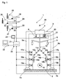
- Fig. 1 shows a schematic cross section through a yarn processing plant.
- the yarn processing system 1 comprises a ring spinning machine 2 and a traveling cleaner 3.
- the traveling cleaner 3 comprises a base unit 4 with a housing in which a fan for generating a negative and / or positive pressure for the Blas Kunststoff- or suction lines and a filter device for filtering by the suction line is disposed of recirculated polluted air (not shown).
- the base unit 4 is arranged on a guide 6 above the workstations and a master spool suspension 8.
- the base unit 4 is arranged to be moved along the track 6 guided track rollers along the spinning machine 2.
- the spinning machine is formed on two sides.
- Each spinning station has a drafting device, which of drafting rollers 11a, 11 b (inlet roller); 12a, 12b (center roller); 13a, 13b (discharge roller) are driven.
- Each spinning station further includes a spindle 14a, 14b, which is driven by a common drive via belt. The torque for the spindles 14a, 14b is taken from a central drive shaft 16, which in the middle of the Spinning machine runs through and is mounted on transverse components, such as traverses or intermediate shields.
- infrared sensors 17a, 17b are provided for detecting the temperature conditions on or at the drafting roller bearing. Furthermore, infrared sensors 18a, 18b are provided for detecting the temperature conditions at the spindle bearing 15a, 15b, at the spindle brake and / or at the whorl. In addition, one or more sensors 19a, 19b are provided for detecting the temperature conditions at the bearings of the central drive shaft.
- a spinning station identification sensor 20 is provided, by means of which the spinning stations are identified by means of readable data memories 21 mounted along the guide rail 6. Thanks to the spinning station identification sensor 20 can be determined at any time, at which spinning station, the Wanderrillian 3 currently is currently.
- the measurement data determined by the spinning station identification sensor 20, as well as by the other sensors 17, 18, 19, are transmitted wirelessly or by wire to a data processing device 34 and evaluated in an evaluation unit 23.
- the assignment of the operating and machine state measurement data to the spinning station identification data is also carried out, so that the state measurement data of the infrared sensors can be assigned to the corresponding spinning stations.
- an output unit 24 is assigned in the form of a panel, via which messages the evaluation unit, for. As error messages are issued to the surgeon.
- the drafting unit drives 25, 26, 27 of the inlet bottom roll 28, middle bottom roll 29 and outlet bottom roll 30 may additionally be equipped with viscosity sensors 31, 32, 33.
- the viscosity sensors 31, 32, 33 are also connected to the data processing device 34 and provide additional measurement data on the condition of the drafting device drive bearings.
- the data processing device 34 is further connected to a higher-level central data processing device 22, to which z. B. several spinning machines are connected.
- the data processing device 34 can also be connected to the machine control or even integrated into it.
- the present invention is used to monitor and diagnose machine damage, which usually leads to overheating of machine components. Furthermore, the invention allows the automated collection of data on machine and / or operating conditions, which can be statistically evaluated.
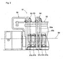
- Fig. 2 shows a yarn processing system 51 with a two-sided yarn processing machine 52, in this case a winder, and a traveling cleaner 53, which is constructed in the same basic principles as those according to Fig. 1 .
- the yarn processing machine 52 includes in the machine longitudinal direction 59 a plurality of juxtaposed workstations 57a, 57b, 57c, 57d, 57e, which here winding units and according to Fig. 1 Spinning positions correspond.
- the traveling cleaner 53 comprises a base body 54, which is arranged to be movable on a roller rail guide according to the double arrow in the machine longitudinal direction above the work stations. On the main body, a suction hose 55a and a blow hose 55b are connected for each machine side.
- a filter cleaning device 58 is provided at the foot or head end of the yarn processing machine 52, via which the filter installed in the base body 54 (not shown) can be cleaned.
- Position 63 shows the traveling cleaner 53 in the docking position to the filter cleaning device 58, in which the filter is emptied via corresponding lines.
- the filter cleaning device 58 is not the subject of the present invention and will therefore not be described in detail.
- Fig. 2 is to show schematically the arrangement of the traveling cleaner in a longitudinal section through the yarn processing machine. The details of the inventive sensor monitoring according to Fig. 1 can also be opened Fig. 2 read and are therefore not shown in detail.
Landscapes
- Engineering & Computer Science (AREA)
- Mechanical Engineering (AREA)
- Textile Engineering (AREA)
- Spinning Or Twisting Of Yarns (AREA)
Applications Claiming Priority (1)
| Application Number | Priority Date | Filing Date | Title |
|---|---|---|---|
| CH4532008 | 2008-03-25 |
Publications (2)
| Publication Number | Publication Date |
|---|---|
| EP2107142A2 true EP2107142A2 (fr) | 2009-10-07 |
| EP2107142A3 EP2107142A3 (fr) | 2012-04-25 |
Family
ID=40974633
Family Applications (1)
| Application Number | Title | Priority Date | Filing Date |
|---|---|---|---|
| EP09000988A Withdrawn EP2107142A3 (fr) | 2008-03-25 | 2009-01-24 | Procédé de fonctionnement d'une machine à filer |
Country Status (2)
| Country | Link |
|---|---|
| EP (1) | EP2107142A3 (fr) |
| CN (1) | CN101545162A (fr) |
Cited By (4)
| Publication number | Priority date | Publication date | Assignee | Title |
|---|---|---|---|---|
| CN104762710A (zh) * | 2013-01-29 | 2015-07-08 | 赵清滨 | 用于降低细纱机纺纱纱线断头的控制方法 |
| EP3009388A3 (fr) * | 2014-09-29 | 2016-08-03 | Premier Evolvics PVT. Ltd. | Système intégré et procédé pour améliorer l'efficacité et la qualité de processus de fabrication de fil textile |
| CN108532048A (zh) * | 2017-03-02 | 2018-09-14 | 里特机械公司 | 用于维修纺织机的工作位的方法 |
| CN114778880A (zh) * | 2022-04-28 | 2022-07-22 | 无锡物联网创新中心有限公司 | 一种多路锭子的并行测速方法及相关装置 |
Families Citing this family (10)
| Publication number | Priority date | Publication date | Assignee | Title |
|---|---|---|---|---|
| DE102009049390A1 (de) * | 2009-10-14 | 2011-04-21 | Oerlikon Textile Gmbh & Co. Kg | Verfahren zum Betreiben einer Kreuzspulen herstellenden Textilmaschine und Kreuzspulen herstellende Textilmaschine |
| DE102010034971A1 (de) * | 2010-08-20 | 2012-02-23 | Oerlikon Textile Gmbh & Co. Kg | Textilmaschine |
| CN103911702A (zh) * | 2014-01-28 | 2014-07-09 | 韵升控股集团有限公司 | 纱线断头监测装置 |
| JP6028767B2 (ja) * | 2014-06-02 | 2016-11-16 | 株式会社豊田自動織機 | リング式紡機の糸継ぎ作業支援装置 |
| EA037819B1 (ru) | 2014-07-31 | 2021-05-25 | Камоцци Диджитал С.Р.Л. | Способ контроля физических параметров текстильного оборудования |
| DE102016111841A1 (de) * | 2016-06-28 | 2017-12-28 | Rieter Ingolstadt Gmbh | Verfahren zum Betreiben einer Arbeitsstelle einer Textilmaschine |
| CN109161994A (zh) * | 2018-09-30 | 2019-01-08 | 苏州多道自动化科技有限公司 | 一种转杯自清洁驱动机构 |
| DE102019116672A1 (de) * | 2019-06-19 | 2020-12-24 | Maschinenfabrik Rieter Ag | Verfahren zur optischen Überwachung einer Textilmaschine, sowie eine Überwachungseinrichtung und ein Computerprogramm |
| CN112342652B (zh) * | 2020-10-05 | 2022-06-10 | 浙江美来亚纺织有限公司 | 一种纺织机用色纺纱清洗除尘装置 |
| CN113463230A (zh) * | 2021-08-04 | 2021-10-01 | 南通双弘纺织有限公司 | 分段式粗纱清洁系统及其清洁方法 |
Citations (3)
| Publication number | Priority date | Publication date | Assignee | Title |
|---|---|---|---|---|
| DE10015136C1 (de) | 2000-03-29 | 2001-04-05 | Neuenhauser Maschb Gmbh & Co K | Wanderreiniger |
| EP1693493A2 (fr) | 2005-02-21 | 2006-08-23 | Murata Kikai Kabushiki Kaisha | Collecteur de poussière et dispositif de nettoyage mobile |
| WO2007082699A1 (fr) | 2006-01-17 | 2007-07-26 | Oerlikon Textile Gmbh & Co. Kg | Métier continu à filer comprenant un nettoyeur mobile et des nettoyeurs de résidus de sous-renvidage |
Family Cites Families (1)
| Publication number | Priority date | Publication date | Assignee | Title |
|---|---|---|---|---|
| DE59103322D1 (de) * | 1990-06-28 | 1994-12-01 | Rieter Ag Maschf | Verfahren und Vorrichtung zum Betrieb einer Ringspinn- oder Zwirnmaschine mit maximal möglicher Spindeldrehzahl. |
-
2009
- 2009-01-24 EP EP09000988A patent/EP2107142A3/fr not_active Withdrawn
- 2009-03-25 CN CN200910129774A patent/CN101545162A/zh active Pending
Patent Citations (3)
| Publication number | Priority date | Publication date | Assignee | Title |
|---|---|---|---|---|
| DE10015136C1 (de) | 2000-03-29 | 2001-04-05 | Neuenhauser Maschb Gmbh & Co K | Wanderreiniger |
| EP1693493A2 (fr) | 2005-02-21 | 2006-08-23 | Murata Kikai Kabushiki Kaisha | Collecteur de poussière et dispositif de nettoyage mobile |
| WO2007082699A1 (fr) | 2006-01-17 | 2007-07-26 | Oerlikon Textile Gmbh & Co. Kg | Métier continu à filer comprenant un nettoyeur mobile et des nettoyeurs de résidus de sous-renvidage |
Cited By (5)
| Publication number | Priority date | Publication date | Assignee | Title |
|---|---|---|---|---|
| CN104762710A (zh) * | 2013-01-29 | 2015-07-08 | 赵清滨 | 用于降低细纱机纺纱纱线断头的控制方法 |
| CN104762710B (zh) * | 2013-01-29 | 2016-09-07 | 郭霞 | 用于降低细纱机纺纱纱线断头的控制方法 |
| EP3009388A3 (fr) * | 2014-09-29 | 2016-08-03 | Premier Evolvics PVT. Ltd. | Système intégré et procédé pour améliorer l'efficacité et la qualité de processus de fabrication de fil textile |
| CN108532048A (zh) * | 2017-03-02 | 2018-09-14 | 里特机械公司 | 用于维修纺织机的工作位的方法 |
| CN114778880A (zh) * | 2022-04-28 | 2022-07-22 | 无锡物联网创新中心有限公司 | 一种多路锭子的并行测速方法及相关装置 |
Also Published As
| Publication number | Publication date |
|---|---|
| EP2107142A3 (fr) | 2012-04-25 |
| CN101545162A (zh) | 2009-09-30 |
Similar Documents
| Publication | Publication Date | Title |
|---|---|---|
| EP2107142A2 (fr) | Procédé de fonctionnement d'une machine à filer | |
| WO2008116759A2 (fr) | Procédé et dispositif de filature par extrusion, de traitement et d'enroulement d'un fil synthétique | |
| DE102016007779A1 (de) | Verfahren zum Überwachen des ordnungsgemäßen Arbeitens der Spinnstellen einer Ringspinnmaschine | |
| CH715390A1 (de) | Verfahren zum Betreiben einer Ringspinnmaschine. | |
| EP3572803B1 (fr) | Capteur de fil destiné à la détection optique d'un fil se déplaçant dans sa direction longitudinale | |
| WO2009073993A1 (fr) | Dispositif et procédé pour le contrôle d'une pluralité de postes de travail d'un métier à filer à anneaux | |
| DE102007023480A1 (de) | Vorrichtung zur Sauberhaltung eines Schutzgehäuses | |
| WO2015049293A1 (fr) | Épurateur de fil et poste de filage d'un métier à filer équipé dudit épurateur, ainsi que procédé permettant de faire fonctionner un poste de filage | |
| DE102009028359A1 (de) | Textilmaschine mit einer Absaugvorrichtung sowie Verfahren zur Steuerung der Absaugvorrichtung einer Textilmaschine | |
| EP2915910B1 (fr) | Procédé et dispositif de fonctionnement d'un métier à filer à rotor | |
| DE102022117598B3 (de) | Vorrichtung zum Abziehen und Aufwickeln von Fäden | |
| DE102008000610B4 (de) | Sensor für eine Textilmaschine | |
| EP1006225A2 (fr) | Méthode et dispositif pour évaluer l'effet des charactéristiques du fil sur l'aspect des surfaces textiles | |
| DE102010034971A1 (de) | Textilmaschine | |
| EP4119706A1 (fr) | Machine à filer ou à bobiner, ainsi que procédé permettant de faire fonctionner une machine à filer ou à bobiner | |
| CH714412A1 (de) | Verfahren zum Betreiben einer Spulmaschine zum Umspulen von Kopsen einer vorangehenden Ringspinnmaschine. | |
| CH706573B1 (de) | Spinnereimaschine. | |
| DE19824078A1 (de) | Verfahren beim Herstellen von verdichtetem Garn und Einrichtung hierfür | |
| WO2013156320A1 (fr) | Unité fonctionnelle d'une zone de bobinage comportant un dispositif d'épissage de fil et un nettoyeur de filé | |
| DE102007015695A1 (de) | Verfahren zum Betreiben einer Kreuzspulen herstellenden Textilmaschine | |
| EP3473756B1 (fr) | Procédé et dispositif de fonctionnement d'un métier à filer à anneaux | |
| EP2982784B1 (fr) | Machine textile multi-position | |
| DE212019000337U1 (de) | Vorspinnmaschine einer Textillinie mit Reinigervorrichtung | |
| DE102009049390A1 (de) | Verfahren zum Betreiben einer Kreuzspulen herstellenden Textilmaschine und Kreuzspulen herstellende Textilmaschine | |
| EP4215655A1 (fr) | Procédé de fonctionnement d'un poste de filage d'un métier à filer à rotor et métier à filer à rotor |
Legal Events
| Date | Code | Title | Description |
|---|---|---|---|
| PUAI | Public reference made under article 153(3) epc to a published international application that has entered the european phase |
Free format text: ORIGINAL CODE: 0009012 |
|
| AK | Designated contracting states |
Kind code of ref document: A2 Designated state(s): AT BE BG CH CY CZ DE DK EE ES FI FR GB GR HR HU IE IS IT LI LT LU LV MC MK MT NL NO PL PT RO SE SI SK TR |
|
| AX | Request for extension of the european patent |
Extension state: AL BA RS |
|
| PUAL | Search report despatched |
Free format text: ORIGINAL CODE: 0009013 |
|
| AK | Designated contracting states |
Kind code of ref document: A3 Designated state(s): AT BE BG CH CY CZ DE DK EE ES FI FR GB GR HR HU IE IS IT LI LT LU LV MC MK MT NL NO PL PT RO SE SI SK TR |
|
| AX | Request for extension of the european patent |
Extension state: AL BA RS |
|
| RIC1 | Information provided on ipc code assigned before grant |
Ipc: D01H 13/32 20060101ALI20120320BHEP Ipc: D01H 13/14 20060101ALI20120320BHEP Ipc: D01H 13/00 20060101ALI20120320BHEP Ipc: D01H 11/00 20060101ALI20120320BHEP Ipc: D01H 1/20 20060101AFI20120320BHEP |
|
| AKY | No designation fees paid | ||
| REG | Reference to a national code |
Ref country code: DE Ref legal event code: R108 |
|
| REG | Reference to a national code |
Ref country code: DE Ref legal event code: R108 Effective date: 20130102 |
|
| STAA | Information on the status of an ep patent application or granted ep patent |
Free format text: STATUS: THE APPLICATION IS DEEMED TO BE WITHDRAWN |
|
| 18D | Application deemed to be withdrawn |
Effective date: 20121026 |