EP2107143A2 - Support de bobine ou de tube pour un dispositif de transport de bobine ou de tube sur une machine textile - Google Patents
Support de bobine ou de tube pour un dispositif de transport de bobine ou de tube sur une machine textile Download PDFInfo
- Publication number
- EP2107143A2 EP2107143A2 EP20090000912 EP09000912A EP2107143A2 EP 2107143 A2 EP2107143 A2 EP 2107143A2 EP 20090000912 EP20090000912 EP 20090000912 EP 09000912 A EP09000912 A EP 09000912A EP 2107143 A2 EP2107143 A2 EP 2107143A2
- Authority
- EP
- European Patent Office
- Prior art keywords
- sliding
- coil
- wall
- annular
- sleeve carrier
- Prior art date
- Legal status (The legal status is an assumption and is not a legal conclusion. Google has not performed a legal analysis and makes no representation as to the accuracy of the status listed.)
- Withdrawn
Links
Images


Classifications
-
- D—TEXTILES; PAPER
- D01—NATURAL OR MAN-MADE THREADS OR FIBRES; SPINNING
- D01H—SPINNING OR TWISTING
- D01H9/00—Arrangements for replacing or removing bobbins, cores, receptacles, or completed packages at paying-out or take-up stations ; Combination of spinning-winding machine
- D01H9/18—Arrangements for replacing or removing bobbins, cores, receptacles, or completed packages at paying-out or take-up stations ; Combination of spinning-winding machine for supplying bobbins, cores, receptacles, or completed packages to, or transporting from, paying-out or take-up stations ; Arrangements to prevent unwinding of roving from roving bobbins
-
- B—PERFORMING OPERATIONS; TRANSPORTING
- B65—CONVEYING; PACKING; STORING; HANDLING THIN OR FILAMENTARY MATERIAL
- B65H—HANDLING THIN OR FILAMENTARY MATERIAL, e.g. SHEETS, WEBS, CABLES
- B65H67/00—Replacing or removing cores, receptacles, or completed packages at paying-out, winding, or depositing stations
- B65H67/06—Supplying cores, receptacles, or packages to, or transporting from, winding or depositing stations
- B65H67/064—Supplying or transporting cross-wound packages, also combined with transporting the empty core
-
- B—PERFORMING OPERATIONS; TRANSPORTING
- B65—CONVEYING; PACKING; STORING; HANDLING THIN OR FILAMENTARY MATERIAL
- B65H—HANDLING THIN OR FILAMENTARY MATERIAL, e.g. SHEETS, WEBS, CABLES
- B65H2701/00—Handled material; Storage means
- B65H2701/30—Handled filamentary material
- B65H2701/31—Textiles threads or artificial strands of filaments
Definitions
- the invention relates to a bobbin or sleeve carrier for a bobbin and tube transport system on a textile machine, wherein the bobbin or sleeve carrier comprises a pin arranged on a base for receiving an empty sleeve or a bobbin, and the base body includes a carrier base, with which the Coil or sleeve carrier directly or indirectly slidably rests on the support surface of a conveyor track of the transport system.
- Coil or sleeve transport systems for the removal of the cops or the coils of and for feeding empty tubes to textile machines, such as spinning machines or winders, are well known.
- the coil or sleeve carriers are normally called peg trays, also called peg trays, which are slidably guided on conveyor tracks designed as carrier rails. Ie. the peg slides slide during their movement towards the work stations or away from the work stations on the mounting rails.
- the mounting rails take on at least a portion of the weight of the loaded with coils or sleeves peg slide.
- the peg slides are thereby pushed or pulled over the conveyor track by means of carriers attached to a conveyor.
- the conveying means are, for example, belts, in particular steel belts, cables or chains, which are guided or also driven by deflection means, in particular deflection rollers.
- the drivers which move the pintle carriages along the conveyor track, i. push, are attached to the conveyor and are moved by this. For this purpose, each pin slide is picked up and guided by its own driver.
- Bobbin carriers move a higher total weight along the transport path.
- the static friction when starting the transport device claimed the conveyor drive extremely strong.
- Object of the present invention is therefore to propose a coil or sleeve carrier for a bobbin or tube transport device of a long textile machines, thanks to which without complex design measures and without increasing the power of the drives, the performance of the transport system is improved.
- the object is achieved in that on the carrier base partially or full surface a sliding pad of high abrasion resistance and high lubricity is applied, which consists of a different material than the main body.
- the sliding pad on the coil or sleeve carrier is preferably made of a thermoplastic, and more preferably of a polyamide (PA), such as PA6, PA66, PA11, PA12, PA46, PA6-G or a copolyamide or polyamide blend.
- PA polyamide
- the polyamides mentioned may be provided with or without additionally integrated solid lubricants or lubricant additives or have a MoS 2 or graphite modification.
- amorphous plastics modified with lubricant additives such as PC, PMMA, PVC-U, ABS or PS are also suitable, even if they do not necessarily achieve the excellent sliding and wear behavior of PA 66.
- the peg carriage includes a body, z. B. in plate form, on which a pin for receiving sleeves or coils or cops is arranged.
- the main body includes a carrier base, which rests on the support surface of the conveyor track.
- the conveyor track is preferably a mounting rail in the form of a sheet metal or extrusion profile made of metal, in particular of aluminum.
- the mounting rail forms a bearing surface for the pin slides.
- the support surface is preferably flat. It can be formed horizontally or inclined.
- a rail support in particular made of plastic, which forms a sliding surface for the journal slide, can be arranged.
- the sliding pad of the journal slide can be one or more parts.
- the slide pad can enter into a cloth, force and / or positive connection with the carrier underside. Combinations of the aforementioned connection forms are therefore also possible.
- the underside of the carrier may be partially or fully covered with the sliding pad.
- the base body is a one-sided or two-sided, at least to the support surface of the conveyor path open hollow body with a preferably annular outer wall, which includes a common cavity or more by one or more webs or inner walls of separate sub-cavities, also called chambers includes ,
- the sliding pad is preferably a partially or completely embedded in the cavity of the body slider.
- the slider is preferably formed in its outer contour opposite to the said cavity. It is fastened by means of form and / or material connection in the cavity.
- the slider protrudes a little at the bottom of the main body, so that the coil or sleeve carrier rests with the slider and not with its underside of the support surface.
- the said projection can, for. B. be 0.1 to 2 mm.
- the projection should not be too large, otherwise the position settings of the gripper and other components coming into contact with the trunnion would have to be changed because of the change in the height of the trunnion carriage in the case of retrofitted transport systems.
- a wear-resistant material for the sliding pad a comparatively slight elevation of the stated order of magnitude is completely sufficient.
- the outer wall of the base body is annular.
- annular outer wall Within the annular outer wall, an annular or polygonal, self-contained inner wall is arranged, which encloses an open central cavity.
- the sliding pad can now be a, in the central cavity of the body partially or completely sunken slider.
- the slider is preferably formed in its outer contour opposite to the said cavity. It is fastened by means of form and / or material connection in the cavity. The slider protrudes a little at the bottom of the main body, so that the coil or sleeve carrier rests with the slider and not with its underside of the support surface
- the base body has an annular outer wall and an inner, preferably concentrically arranged to the outer wall, annular inner wall, which encloses an open central cavity.
- the sliding pad can now be partially or completely embedded in the central cavity.
- the slider in its outer contour is preferably formed opposite to the central cavity. It is fastened by means of form and / or material connection in the cavity.
- Said sliding body may be an annular body or a solid body.
- the slider can be provided with radial excess, which can be introduced by radial compression in the corresponding cavity in the body and is positively trapped by radial relief of the ring body under spring back because of the restoring force in the cavity.
- the sliding pad may be an annular slider with an annular gap and resilient properties.
- the slider is designed here in the functional design of an inner locking ring. That the slider is inserted by radially compressing the annular gap in a preferably circular or annular cavity in the body and and sets by radial relief of the ring body due to the restoring force of the annular leg form-fitting firmly on the inner wall of the cavity.
- the positive connection or in addition to the positive connection can also be a material connection, for.
- a material connection for.
- the base body and the slider are already connected to each other during the manufacturing process. So z. B. the main body are molded in an injection molding together with the slider in a two-component injection molding.
- the sliding body can also be connected as an insert during the injection molding process for the production of the main body with this.
- the sliding body can also be screwed into the cavity in the base body via a screw connection.
- the slider may also be formed conically for the purpose of producing a positive connection transverse to the radial extent.
- a clip or snap-in connection between the body and slider is conceivable.
- a plurality of radially inwardly spaced and spaced apart recessed connecting webs are arranged between the annular outer wall and the annular inner wall, which connect the outer wall with the annular inner wall and effect in this way a reinforcement of the structure of the base body
- the sliding pad can now be an annular sliding body, which is arranged resting on the recessed connecting webs between the outer wall and the inner wall. It can now be provided both between the outer wall and the inner wall, as just described, as well as in the central cavity, as described above, a sliding body according to one of the embodiments described above. But it can also be provided at the appropriate place only a slider.
- the sliding surface or the base body of the underside of the base body in each case before, so that the pin carriage rests with the sliding body of the support surface of the support rail or conveyor track.
- the sliding surface may be the main body, i. the outer and / or inner wall project by about 0.1 to 0.2 mm.
- the main body or the entire pin slide consist of a plastic, preferably of a thermoplastic material, such as.
- a plastic preferably of a thermoplastic material, such as.
- a polyester PBT or PET.
- journal slide according to the invention can be used in transport systems on spinning machines, in particular ring spinning machines, twisting machines or winding machines.
- the sliding pad according to the invention on the trunnion carriage considerably reduces the friction between the conveyor track and the trunnion carriage, so that, despite an increase of moving trunnion carriages in the case of long spinning machines, no increase in the drive power is required and the energy consumption can be further optimized. Moreover, the good sliding properties, in particular the excellent dry friction properties, of the wear-resistant sliding pad are retained over a long service life.
- the friction coefficient of more than 0.4 ⁇ , in particular 0.44 ⁇ can be reduced to less than 0.3 ⁇ , in particular to 0.23 ⁇ .
- the present invention also has the advantages that the pin carrier can be equipped in a simple manner and with little technical and economic effort with a low-friction and wear-resistant sliding surface. In this case, recourse can be had to the conventional form of the trunnion carriage without having to laboriously modify it. This therefore also allows the retrofitting of countless already in circulation peg slide with a low-friction and wear-resistant sliding surface.
- the spinning machine or the conveyor, supplies the carriers or the coils to a "sink” and receives carriers or sleeves from a "source”.
- the "sink” and the "source” can by a single processing unit, for. As a winder, are formed. But they can also be formed by entry or exit points of a transport system that can work automatically, semi-automatically or even hand-operated.
- the transport system delivers z. B. coils to predetermined or indefinite points and receives sleeves from the same or even from other places.
- the Fig. 1 shows a schematic plan view of a ring spinning machine 1 with a guided around the ring spinning endless conveyor.
- the ring spinning machine 1 has on opposite machine sides parallel to each other spinning stations groups 12a and 12b, each consisting of only schematically indicated spinning stations 11. Further details of the ring spinning machine 1, in particular the machine heads are not shown, because it is so far the usual and known arrangements. The number of spinning units 11 is reproduced greatly reduced for the sake of clarity.
- the two spinning station groups 12a, 12b is designed as an endless conveyor conveyor 21 guided around in the form of a vertically extending steel strip.
- the steel strip is placed around deflection rollers 13, 14, 15, 16 with a vertical axis at the two ends of the parallel and in alignment with each other spin groups 12a, 12b.
- deflection rollers 13, 14, 15, 16 with a vertical axis at the two ends of the parallel and in alignment with each other spin groups 12a, 12b.
- pin slides 2 are arranged one behind the other at a distance and in contact with the driving fingers, which according to Fig. 2 from a circular disk-shaped main body 3 (plate) and a sleeve journal arranged perpendicular thereto 4, and preferably in the region of an arranged between the sleeve pin 4 and the base body 3 widened foot 9 are engaged behind by the driving fingers 10.
- sleeve changing devices 20 which may be formed as in classic Doffern and serve to remove from the spindles of the spinning units 11 full sleeves (cops or spools) and instead choircken empty tubes on the spindles, which by means of the endless conveyor 21 to the individual spinning units eleventh have been introduced.
- a conveying connection (not shown) to a winding unit or a cop removing and receiving unit can be provided.
- the guide rail 6 is arranged on or on the machine frame.
- The, preferably designed as a hollow profile guide rail 6 comprises a flat, horizontally oriented guide or support surface 7, on which a band-shaped plastic sliding pad can be arranged.
- the peg slide 2 is slidably guided with its arranged on the underside of the base body 3 slide pad 5 on the support surface 7 and the plastic pad thereon ( Fig. 2 ).
- the pin slide 2 has between the pin 4 and the base 3 a slightly opposite the pin 4 widened foot 9, which is engaged behind by a driving finger 10.
- the driver finger 10 is connected via a holding arm with the carrier body 22 of the driver 8, which is fastened with fastening means on the vertical conveyor belt 21.
- the driver 8 is guided via guide means along the guide rail 6.
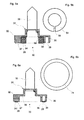
- Fig. 3 shows the bottom view of a known pin slide 31 as shown in Fig. 4a .
- 5a and 6a is also shown in cross-sectional view.
- the base body 32 is a hollow body which is open on one side, facing the bearing surface, with an annular outer wall 35 and has a lower side 30.
- an annular outer wall 34 Within the annular outer wall 34 is an annular, arranged concentrically to the outer wall and self-contained inner wall 36 is arranged, which encloses an open central cavity 29.
- the central cavity 29 has, to the side opposite the underside an opening through which the pin 33 is fixed to the base body 32.
- this feature is not relevant to the present invention and is therefore not intended to be limiting.
- the first embodiment according to Fig. 4a and 4b shows the pin carriage 31 with a slider 34.
- the slider 34 is in the form of a circular solid body. This is completely embedded up to a front-side stop 39 in the central cavity 29 of the body 32 and sits in this form-fitting firmly.
- the sliding body is formed in its outer contour opposite to the central cavity, wherein the base body 32 may have a small radial excess relative to the cavity.
- the slider 32 is connected by means of a form and / or material connection with the base body 32.
- the second embodiment according to Fig. 5a and 5b shows the pin carriage 31 with a slider 54.
- the slider 54 is an annular body with annular gap 59, which in its outer contour relative to the cavity 29 has a radial excess.
- the slider is designed here in the functional design of an inner locking ring, which is insertable by radial compression of the annular gap 59 in the annular cavity 29 in the base body 32 and by radial relief of the annular body by spring back form-fitting manner on the inner wall of the cavity 29 determines.
- the slider 54 is completely embedded up to an end stop 39 in the central cavity 29 of the body 32.
- the third embodiment according to Fig. 6a and 6b shows the pin carriage 31 with a slider 74.
- the slider 74 is an annular, flat body which rests between the outer wall 35 and the inner wall 36 on the recessed connecting webs 37. Since the connecting webs 37 are set back, the sliding body 74 extends beyond the supporting edge of the underside into the main body 32.
- the slider 74 is z. B. glued to the main body 32.
- the sliding body 31 is according to the embodiments according to 4 to 6 at the bottom of the body 32 slightly before, so that the coil or sleeve support 31 rests with the sliding surface 28 of the slider 34, 54, 74 and not with the end edges of its support bottom 30 of the support surface.
Landscapes
- Engineering & Computer Science (AREA)
- Mechanical Engineering (AREA)
- Textile Engineering (AREA)
- Spinning Or Twisting Of Yarns (AREA)
- Looms (AREA)
Applications Claiming Priority (1)
| Application Number | Priority Date | Filing Date | Title |
|---|---|---|---|
| CH4522008 | 2008-03-25 |
Publications (1)
| Publication Number | Publication Date |
|---|---|
| EP2107143A2 true EP2107143A2 (fr) | 2009-10-07 |
Family
ID=40974629
Family Applications (1)
| Application Number | Title | Priority Date | Filing Date |
|---|---|---|---|
| EP20090000912 Withdrawn EP2107143A2 (fr) | 2008-03-25 | 2009-01-23 | Support de bobine ou de tube pour un dispositif de transport de bobine ou de tube sur une machine textile |
Country Status (2)
| Country | Link |
|---|---|
| EP (1) | EP2107143A2 (fr) |
| CN (1) | CN101545161A (fr) |
Cited By (1)
| Publication number | Priority date | Publication date | Assignee | Title |
|---|---|---|---|---|
| CN115928342A (zh) * | 2023-01-09 | 2023-04-07 | 河北力科纺织有限责任公司 | 一种管纱后处理工艺设备 |
Families Citing this family (9)
| Publication number | Priority date | Publication date | Assignee | Title |
|---|---|---|---|---|
| CN103498222A (zh) * | 2013-09-22 | 2014-01-08 | 慈溪在业机械制造有限公司 | 一种高强度嵌入式耐磨凸盘 |
| CN103668595A (zh) * | 2013-11-20 | 2014-03-26 | 慈溪在业机械制造有限公司 | 新型嵌入式耐磨凸盘 |
| CN103668601B (zh) * | 2013-11-30 | 2015-12-02 | 天津宏大纺织机械有限公司 | 用于粗细联输送系统的活动纱架 |
| DE102014001779A1 (de) * | 2014-02-12 | 2015-08-13 | Atlantic C Handels- Und Beratungs-Gmbh | Vorrichtung zum Lagern von Filamentspulen |
| CN104047104B (zh) * | 2014-07-01 | 2016-05-04 | 苏州万图明电子软件有限公司 | 多功能自动纺织机 |
| CN105316817A (zh) * | 2015-11-04 | 2016-02-10 | 经纬纺织机械股份有限公司 | 一种环锭细纱机集体落纱齿块钢带导向机构 |
| CN105386172B (zh) * | 2015-12-04 | 2018-08-28 | 晋中经纬泓鑫机械有限公司 | 一种输送纱管装置及方法 |
| CN109353880B (zh) * | 2018-08-31 | 2024-04-12 | 杭州锐冠科技有限公司 | 一种输送铝型材及筒管纱输送装置 |
| CN110106587A (zh) * | 2019-05-10 | 2019-08-09 | 经纬智能纺织机械有限公司 | 一种环锭细纱机钢带式托盘输送下托座固定装置 |
Citations (2)
| Publication number | Priority date | Publication date | Assignee | Title |
|---|---|---|---|---|
| WO1990003460A1 (fr) | 1988-09-24 | 1990-04-05 | Maschinenfabrik Rieter Ag | Metier a filer avec convoyeur sans fin |
| EP0517668A1 (fr) | 1991-06-02 | 1992-12-09 | Maschinenfabrik Rieter Ag | Transport de bobines et tubes de bobine dans les métiers à filer |
-
2009
- 2009-01-23 EP EP20090000912 patent/EP2107143A2/fr not_active Withdrawn
- 2009-03-20 CN CN200910129815A patent/CN101545161A/zh active Pending
Patent Citations (2)
| Publication number | Priority date | Publication date | Assignee | Title |
|---|---|---|---|---|
| WO1990003460A1 (fr) | 1988-09-24 | 1990-04-05 | Maschinenfabrik Rieter Ag | Metier a filer avec convoyeur sans fin |
| EP0517668A1 (fr) | 1991-06-02 | 1992-12-09 | Maschinenfabrik Rieter Ag | Transport de bobines et tubes de bobine dans les métiers à filer |
Cited By (1)
| Publication number | Priority date | Publication date | Assignee | Title |
|---|---|---|---|---|
| CN115928342A (zh) * | 2023-01-09 | 2023-04-07 | 河北力科纺织有限责任公司 | 一种管纱后处理工艺设备 |
Also Published As
| Publication number | Publication date |
|---|---|
| CN101545161A (zh) | 2009-09-30 |
Similar Documents
| Publication | Publication Date | Title |
|---|---|---|
| EP2107143A2 (fr) | Support de bobine ou de tube pour un dispositif de transport de bobine ou de tube sur une machine textile | |
| DE60005792T2 (de) | Fadenchangiervorrichtung mit nockenfolger zum wickeln einer spule | |
| EP1905875B1 (fr) | Dispositif de transport de bobines pour un métier à filer | |
| EP1194622B1 (fr) | Fournisseur de fil destine a des machines textiles | |
| EP2034060A1 (fr) | Machine textile dotée d'un banc d'étirage | |
| EP3529180B1 (fr) | Système de transport | |
| EP3279117A1 (fr) | Convoyeur destiné au transport de produits | |
| DE102011118303A1 (de) | Förderanlage mit einer Förderkette und Tragsegment für einen Förderträger einer Förderkette | |
| DE1954261A1 (de) | Schwenkbare Walzenandrueckvorrichtung | |
| DE202013007959U1 (de) | Türkämpfer für eine Aufzugstür | |
| DE202007011954U1 (de) | Streckwerk und Unterwalzen-Lagerschlitten | |
| WO1995025056A1 (fr) | Convoyeur aerien a simple voie ou a double voie | |
| DD287538A5 (de) | Haengefoerdersystem | |
| EP0506994A1 (fr) | Transporteur à rouleaux entraîné par courroie | |
| DE3407804A1 (de) | Spulentransportvorrichtung | |
| EP3225575B1 (fr) | Guidage de chaîne de traînage d'une machine textile fabriquant des bobines croisées | |
| DE102017011293A1 (de) | Laufbahn, Fördereinrichtung und Verfahren zur Montage einer Laufbahn | |
| DE3432245C2 (fr) | ||
| DE102010046573B4 (de) | Verfahren und Vorrichtung zum Zuführen eines Kunststoffmaterials zu einer Extruderschnecke | |
| EP0964183B1 (fr) | Courroie pour la production d'un rouleau d' ouate | |
| DE19540177C2 (de) | Fördersystem | |
| EP1215313A2 (fr) | Armature pour un canal d'aspiration d'un dispositif de condensation de fibres situé dans un métier à filer | |
| DE202007012066U1 (de) | Coregarn-Einrichtung und Spulenseparator | |
| DE19612708A1 (de) | Spinnmaschine mit Endlosförderer für Hülsenzapfen tragende Zapfenträger | |
| DE102006011558A1 (de) | Angetriebene Rollenbahnkurve und Förderbahn mit einer solchen Rollenbahnkurve |
Legal Events
| Date | Code | Title | Description |
|---|---|---|---|
| PUAI | Public reference made under article 153(3) epc to a published international application that has entered the european phase |
Free format text: ORIGINAL CODE: 0009012 |
|
| AK | Designated contracting states |
Kind code of ref document: A2 Designated state(s): AT BE BG CH CY CZ DE DK EE ES FI FR GB GR HR HU IE IS IT LI LT LU LV MC MK MT NL NO PL PT RO SE SI SK TR |
|
| AX | Request for extension of the european patent |
Extension state: AL BA RS |
|
| STAA | Information on the status of an ep patent application or granted ep patent |
Free format text: STATUS: THE APPLICATION IS DEEMED TO BE WITHDRAWN |
|
| 18D | Application deemed to be withdrawn |
Effective date: 20120801 |