EP2107166A2 - Plaque de fixation pour un coupleur rapide - Google Patents
Plaque de fixation pour un coupleur rapide Download PDFInfo
- Publication number
- EP2107166A2 EP2107166A2 EP09007768A EP09007768A EP2107166A2 EP 2107166 A2 EP2107166 A2 EP 2107166A2 EP 09007768 A EP09007768 A EP 09007768A EP 09007768 A EP09007768 A EP 09007768A EP 2107166 A2 EP2107166 A2 EP 2107166A2
- Authority
- EP
- European Patent Office
- Prior art keywords
- mounting plate
- attachment
- quick
- receiving
- change device
- Prior art date
- Legal status (The legal status is an assumption and is not a legal conclusion. Google has not performed a legal analysis and makes no representation as to the accuracy of the status listed.)
- Granted
Links
Images




Classifications
-
- E—FIXED CONSTRUCTIONS
- E02—HYDRAULIC ENGINEERING; FOUNDATIONS; SOIL SHIFTING
- E02F—DREDGING; SOIL-SHIFTING
- E02F3/00—Dredgers; Soil-shifting machines
- E02F3/04—Dredgers; Soil-shifting machines mechanically-driven
- E02F3/28—Dredgers; Soil-shifting machines mechanically-driven with digging tools mounted on a dipper- or bucket-arm, i.e. there is either one arm or a pair of arms, e.g. dippers, buckets
- E02F3/36—Component parts
- E02F3/3604—Devices to connect tools to arms, booms or the like
- E02F3/3609—Devices to connect tools to arms, booms or the like of the quick acting type, e.g. controlled from the operator seat
- E02F3/3613—Devices to connect tools to arms, booms or the like of the quick acting type, e.g. controlled from the operator seat with means for absorbing any play therebetween
-
- E—FIXED CONSTRUCTIONS
- E02—HYDRAULIC ENGINEERING; FOUNDATIONS; SOIL SHIFTING
- E02F—DREDGING; SOIL-SHIFTING
- E02F3/00—Dredgers; Soil-shifting machines
- E02F3/04—Dredgers; Soil-shifting machines mechanically-driven
- E02F3/28—Dredgers; Soil-shifting machines mechanically-driven with digging tools mounted on a dipper- or bucket-arm, i.e. there is either one arm or a pair of arms, e.g. dippers, buckets
- E02F3/36—Component parts
- E02F3/3604—Devices to connect tools to arms, booms or the like
- E02F3/3609—Devices to connect tools to arms, booms or the like of the quick acting type, e.g. controlled from the operator seat
- E02F3/3618—Devices to connect tools to arms, booms or the like of the quick acting type, e.g. controlled from the operator seat with two separating hooks
-
- E—FIXED CONSTRUCTIONS
- E02—HYDRAULIC ENGINEERING; FOUNDATIONS; SOIL SHIFTING
- E02F—DREDGING; SOIL-SHIFTING
- E02F3/00—Dredgers; Soil-shifting machines
- E02F3/04—Dredgers; Soil-shifting machines mechanically-driven
- E02F3/28—Dredgers; Soil-shifting machines mechanically-driven with digging tools mounted on a dipper- or bucket-arm, i.e. there is either one arm or a pair of arms, e.g. dippers, buckets
- E02F3/36—Component parts
- E02F3/3604—Devices to connect tools to arms, booms or the like
- E02F3/3609—Devices to connect tools to arms, booms or the like of the quick acting type, e.g. controlled from the operator seat
- E02F3/3627—Devices to connect tools to arms, booms or the like of the quick acting type, e.g. controlled from the operator seat with a hook and a longitudinal locking element
Definitions
- the invention relates to a mounting plate for quick-change devices with the features of the introductory part of claim 1.
- Attachment plates for known quick-change devices have one or two over the width of the mounting plate integrally continuous receiving bolts (coupling rods), via a mounted on the free end of an excavator boom attachment (spoon, hydraulic breaker, etc.), for example, hooked by hooking in hook-shaped recesses on the quick-change device can.
- the known locating bolts are integrally formed continuously in the known mounting plates and fixedly connected to the attachment plate connected to the attachment, for example by welding.
- the invention is based on the object to provide a mounting plate of the type mentioned genus available in which recording bolts can be renewed for themselves if necessary.
- the coupling rod is releasably secured to the mounting plate, it can, if necessary, for. B. in case of damage or if it is worn out, be replaced easily. This no matter whether the coupling rod as provided in one embodiment of the invention integrally or according to another embodiment of the invention divided, z. B. divided into two receiving bolts, is executed.
- the locating bolt is stepped and has an eccentric part, so that by attacking the hooks of the quick-change device resulting wear of the locating bolt can be compensated by turning the locating bolt without the receiving bolt must be replaced altogether.
- a locating bolt can be used longer without the attachment to the excavator boom is no longer securely and functionally attached. Only when the possibility of adjusting is exhausted is the "eccentric" locating bolt replaced.
- the locating bolts are fixed in the mounting plate according to the invention by fastening screws.
- the receiving bolts are conically formed at their inner, mutually facing ends, and engage in corresponding, provided for example in a receiving sleeve, receiving zones in the mounting plate.
- a secure and position-defined seat of the locating bolt of the mounting plate according to the invention is ensured.
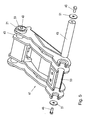
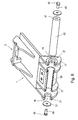
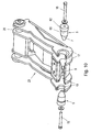
- FIG. 1 a mounting plate in an oblique view
- Fig. 2 the mounting plate in an oblique view, partially broken away with the locating bolt in exploded view
- Figure 3 another embodiment of a mounting plate with receiving bolts in exploded view
- Fig. 4 the mounting plate Fig. 3 in another view
- Figure 5 partially broken away an embodiment with integral coupling rod
- Fig. 6 partly broken away another embodiment with one-piece coupling rod
- Fig. 7 a mounting plate with locating bolts with eccentric parts
- Fig. 8 a pickup bolt from Fig. 7
- Fig. 9 the receiving plate of Fig. 7 with recording bolts in exploded view
- Fig. 10 another embodiment in an exploded view.
- mounting plate 1 is attached to a to be determined on an excavator boom via a quick-change device attachment (not shown), z.
- a quick-change device attachment (not shown), z.
- a spoon an excavator spoon, a slope spoon, a hydraulic hammer, etc.
- the attachment to a quick-change device which is provided at the free end of an excavator boom, are attached.
- the mounting plate 1 has at one end a bolt receptacle 3, which is continuously open, and in which one on the quick-change device slidably guided latch is inserted to set the mounting plate 1 with attached to her attachment to the quick-change device.
- the attachment plate 1 has receiving bolts 5, which form a coupling rod and on which the bolt receptacle 3 opposite end of the mounting plate 1 are provided. If an attachment is to be set on the mounting plate 1 on a quick-change device, hook the quick-change device to the receiving bolt 5, so that after advancing the latch of the quick-change device in the bolt receptacle 3, the attachment via the mounting plate 1 on the quick-change device and thus the excavator boom is fixed ,
- the coupling rod is not continuous (integrally) formed, but is formed in the inventive mounting plate 1 of two receiving bolts 5, as in Fig. 2 is shown.
- two receiving bolts 5 are provided, which are formed at one end (inner end) with a cone 7.
- a receiving sleeve 9 is fixed to the bolt receptacle 3 opposite end, the cavity is formed at its ends widening conically, to record with cones 11, the conically tapered ends 7 of the locating bolt 5 fit.
- threaded holes 13 are further provided, in the fastening screws 15 which define the locating bolt 5 in the receiving sleeve 9, are screwed.
- FIG. 1 and 2 shown embodiments of a mounting plate 1 is an unillustrated attachment to the in the Fig. 1 attached down side of the mounting plate 1.
- FIG. 5 and 6 Embodiments of mounting plates 1 and 41 are shown, in which the coupling rods 43 are integrally formed. As in the other embodiments, the coupling rods 43 pass through holes 19 in the cheeks 17 of the mounting plates 1 and 41st
- screws 45 are provided, which are coaxially aligned with the respective coupling rod 43 and screwed into threaded holes 47 at both ends of the coupling rod 43.
- the heads 49 of the screws 47 are about washers 51 on the outer surfaces of the outer cheeks 17, or as in the in Fig. 5 and 6 shown embodiments of rings 21, which correspond to the protective rings 21 of the other embodiments.
- a sleeve 53 is fixed, in which the middle portion of the coupling rod is received and protected.
- one-piece coupling rods 43 may be combined with formed by receiving bolts 5, so divided coupling rods.
- the locating bolt 5 is stepped ( Fig. 8 ).
- the locating pin 5 has a cylindrical portion 60 which is eccentric to the portion 62 of the locating pin 5 disposed in the through hole 19 received in the cheeks 17 in the mounting plate 1.
- the front conical tip 7 of the receiving pin 5 of the FIGS. 7 to 9 is again formed concentric with the section 62 and the receiving opening 19 in the inner cheeks 17 of the mounting plate 1.
- the locating bolt 5 of FIGS. 7 to 9 is set in the mounting plate 1, as previously based on the Figures 1 and 2 has been described, namely with the aid of two fastening screws 15 which are screwed into the threaded holes 13 in the receiving sleeve 9.
- the eccentric locating bolt 5 can be rotated, so that wear or other wear or damage to the for coupling (engaging the hooks of a quick-change device) of the mounting plate 1 with a working device (attachment) essential area 60 of the locating bolt 5 are compensated can.
- Receiving bolt 5 with an eccentric portion 60 can also in mounting plates 23 in the FIGS. 3 to 5 shown embodiment can be used. This is in Fig. 10 shown.
Landscapes
- Engineering & Computer Science (AREA)
- Mechanical Engineering (AREA)
- Mining & Mineral Resources (AREA)
- Civil Engineering (AREA)
- General Engineering & Computer Science (AREA)
- Structural Engineering (AREA)
- Pivots And Pivotal Connections (AREA)
- Connection Of Plates (AREA)
- Shovels (AREA)
Priority Applications (1)
| Application Number | Priority Date | Filing Date | Title |
|---|---|---|---|
| AT0083409U AT11152U1 (de) | 2006-03-27 | 2009-12-29 | Anbauplatte für schnellwechselvorrichtung |
Applications Claiming Priority (3)
| Application Number | Priority Date | Filing Date | Title |
|---|---|---|---|
| AT0023406U AT9147U1 (de) | 2006-03-27 | 2006-03-27 | Anbauplatte für eine schnellwechselvorrichtung |
| AT0050506U AT9344U1 (de) | 2006-03-27 | 2006-06-29 | Anbauplatte für eine schnellwechselvorrichtung |
| EP07450009A EP1842970B1 (fr) | 2006-03-27 | 2007-01-25 | Plaque de fixation pour un coupleur rapide. |
Related Parent Applications (2)
| Application Number | Title | Priority Date | Filing Date |
|---|---|---|---|
| EP07450009A Division EP1842970B1 (fr) | 2006-03-27 | 2007-01-25 | Plaque de fixation pour un coupleur rapide. |
| EP07450009.1 Division | 2007-01-25 |
Publications (3)
| Publication Number | Publication Date |
|---|---|
| EP2107166A2 true EP2107166A2 (fr) | 2009-10-07 |
| EP2107166A3 EP2107166A3 (fr) | 2010-03-17 |
| EP2107166B1 EP2107166B1 (fr) | 2012-10-31 |
Family
ID=38117180
Family Applications (2)
| Application Number | Title | Priority Date | Filing Date |
|---|---|---|---|
| EP07450009A Active EP1842970B1 (fr) | 2006-03-27 | 2007-01-25 | Plaque de fixation pour un coupleur rapide. |
| EP09007768A Active EP2107166B1 (fr) | 2006-03-27 | 2007-01-25 | Plaque de fixation pour un coupleur rapide |
Family Applications Before (1)
| Application Number | Title | Priority Date | Filing Date |
|---|---|---|---|
| EP07450009A Active EP1842970B1 (fr) | 2006-03-27 | 2007-01-25 | Plaque de fixation pour un coupleur rapide. |
Country Status (4)
| Country | Link |
|---|---|
| EP (2) | EP1842970B1 (fr) |
| AT (3) | AT9344U1 (fr) |
| DE (1) | DE502007006576D1 (fr) |
| SI (1) | SI1842970T1 (fr) |
Cited By (2)
| Publication number | Priority date | Publication date | Assignee | Title |
|---|---|---|---|---|
| DE102017130436A1 (de) * | 2017-12-19 | 2019-06-19 | Oilquick Deutschland Gmbh | Adapter, Schnellwechsler und Schnellwechselsystem |
| EP3708716A1 (fr) * | 2019-03-15 | 2020-09-16 | Markus Riedlberger | Dispositif de connexion |
Families Citing this family (3)
| Publication number | Priority date | Publication date | Assignee | Title |
|---|---|---|---|---|
| GB2466017B (en) * | 2008-12-08 | 2012-10-17 | Jcb Compact Products Ltd | Mounting assembly |
| AT515695B1 (de) | 2014-11-20 | 2015-11-15 | Baumaschinentechnik Ges M B H | Kupplung für Baumaschinen |
| AT15516U1 (de) | 2016-07-14 | 2017-11-15 | Baumaschinentechnik Ges M B H | Kupplung für Baumaschinen |
Citations (5)
| Publication number | Priority date | Publication date | Assignee | Title |
|---|---|---|---|---|
| EP0616084A1 (fr) | 1993-03-19 | 1994-09-21 | TREVI BENNE S.r.l. | Attelage rapide autobloquant pour l'attache des godets ou d'autres outils sur engins de terrassement |
| AT2087U1 (de) | 1997-04-14 | 1998-04-27 | Baumaschinentechnik Ges M B H | Schnellwechselvorrichtung für bagger mit verriegelungsanzeige |
| WO1998046835A1 (fr) | 1997-04-14 | 1998-10-22 | Baumaschinentechnik Gesellschaft Mbh | Dispositif de montage rapide pour pelle mecanique |
| AT413117B (de) | 2003-04-24 | 2005-11-15 | Baumaschinentechnik Ges M B H | Anbauplatte für schnellwechselvorrichtung |
| AT8070U1 (de) | 2004-05-10 | 2006-01-15 | Baumaschinentechnik Ges M B H | Schnellwechselvorrichtung für bagger |
Family Cites Families (14)
| Publication number | Priority date | Publication date | Assignee | Title |
|---|---|---|---|---|
| US4207693A (en) * | 1976-08-18 | 1980-06-17 | Hemphill Charles W | Backhoe bucket adapter bushing and pin method and apparatus |
| ZA817596B (en) * | 1980-11-17 | 1982-10-27 | Eimco Great Britain Ltd | A coupling mechanism |
| JPS634125A (ja) | 1986-06-24 | 1988-01-09 | Hitachi Constr Mach Co Ltd | 油圧シヨベルのアタツチメント装着装置 |
| US4813163A (en) | 1988-01-26 | 1989-03-21 | Construction Technology, Inc. | Alignment fitting for attaching implements to a backhoe |
| US4974349A (en) * | 1989-11-02 | 1990-12-04 | Robert Timmons | Backhoe compactor apparatus |
| FR2697302B1 (fr) * | 1992-10-23 | 1994-12-30 | Dorguin Jean Pierre | Dispositif d'attache rapide pour équipement d'engin de génie civil et de manutention. |
| DE9313694U1 (de) * | 1993-09-10 | 1994-02-10 | Depka, Klaus von, 52159 Roetgen | Automatische Baggerschaufel-Wechselvorrichtung |
| JP3710012B2 (ja) | 1996-09-20 | 2005-10-26 | 小松ゼノア株式会社 | バケットの取付構造 |
| US5927665A (en) | 1998-07-02 | 1999-07-27 | Allied Construction Products, Inc. | Implement mounting system |
| JPH11117345A (ja) | 1997-10-15 | 1999-04-27 | Komatsu Ltd | 作業機アタッチメント取付装置 |
| JPH11303125A (ja) * | 1998-04-22 | 1999-11-02 | Hitachi Constr Mach Co Ltd | バックホウ式バケット |
| MXPA04006847A (es) * | 2002-01-14 | 2004-12-08 | Kent Demolition Inc | Unidad conectora para montar un implemento en un montacargas. |
| WO2004001141A1 (fr) * | 2002-06-24 | 2003-12-31 | Jrb Company, Inc. | Ensemble bras pour appareil d'excavation et son procede d'utilisation |
| DE102005037105C5 (de) * | 2005-08-03 | 2011-06-22 | Lehnhoff Hartstahl GmbH & Co. KG, 76534 | Adapter für ein Arbeitsgerät als Teil einer Schnellwechselvorrichtung und Schnellwechselvorrichtung |
-
2006
- 2006-06-29 AT AT0050506U patent/AT9344U1/de not_active IP Right Cessation
-
2007
- 2007-01-25 EP EP07450009A patent/EP1842970B1/fr active Active
- 2007-01-25 DE DE502007006576T patent/DE502007006576D1/de active Active
- 2007-01-25 EP EP09007768A patent/EP2107166B1/fr active Active
- 2007-01-25 SI SI200730598T patent/SI1842970T1/sl unknown
- 2007-01-25 AT AT07450009T patent/ATE500386T1/de active
-
2009
- 2009-12-29 AT AT0083409U patent/AT11152U1/de not_active IP Right Cessation
Patent Citations (5)
| Publication number | Priority date | Publication date | Assignee | Title |
|---|---|---|---|---|
| EP0616084A1 (fr) | 1993-03-19 | 1994-09-21 | TREVI BENNE S.r.l. | Attelage rapide autobloquant pour l'attache des godets ou d'autres outils sur engins de terrassement |
| AT2087U1 (de) | 1997-04-14 | 1998-04-27 | Baumaschinentechnik Ges M B H | Schnellwechselvorrichtung für bagger mit verriegelungsanzeige |
| WO1998046835A1 (fr) | 1997-04-14 | 1998-10-22 | Baumaschinentechnik Gesellschaft Mbh | Dispositif de montage rapide pour pelle mecanique |
| AT413117B (de) | 2003-04-24 | 2005-11-15 | Baumaschinentechnik Ges M B H | Anbauplatte für schnellwechselvorrichtung |
| AT8070U1 (de) | 2004-05-10 | 2006-01-15 | Baumaschinentechnik Ges M B H | Schnellwechselvorrichtung für bagger |
Cited By (3)
| Publication number | Priority date | Publication date | Assignee | Title |
|---|---|---|---|---|
| DE102017130436A1 (de) * | 2017-12-19 | 2019-06-19 | Oilquick Deutschland Gmbh | Adapter, Schnellwechsler und Schnellwechselsystem |
| EP3708716A1 (fr) * | 2019-03-15 | 2020-09-16 | Markus Riedlberger | Dispositif de connexion |
| DE102019106613B4 (de) | 2019-03-15 | 2023-01-12 | Markus Riedlberger | Verbindungsvorrichtung |
Also Published As
| Publication number | Publication date |
|---|---|
| AT11152U1 (de) | 2010-05-15 |
| SI1842970T1 (sl) | 2011-06-30 |
| EP1842970A3 (fr) | 2008-12-31 |
| EP2107166B1 (fr) | 2012-10-31 |
| EP2107166A3 (fr) | 2010-03-17 |
| EP1842970A2 (fr) | 2007-10-10 |
| DE502007006576D1 (de) | 2011-04-14 |
| ATE500386T1 (de) | 2011-03-15 |
| EP1842970B1 (fr) | 2011-03-02 |
| AT9344U1 (de) | 2007-08-15 |
Similar Documents
| Publication | Publication Date | Title |
|---|---|---|
| EP1842970B1 (fr) | Plaque de fixation pour un coupleur rapide. | |
| EP2940216B1 (fr) | Protection latérale de lame de chasse-neige | |
| DE102016213773A1 (de) | Befestigungselement | |
| EP3564443A1 (fr) | Dispositif outil auxiliaire | |
| DE3630804C2 (fr) | ||
| EP2001627A1 (fr) | Pince de démolition | |
| DE2918485C2 (fr) | ||
| AT508185B1 (de) | Verdrehsicherer bolzen | |
| EP2009180B1 (fr) | Appareil de démoulage pour un rouleau compresseur | |
| AT413117B (de) | Anbauplatte für schnellwechselvorrichtung | |
| EP1651818A1 (fr) | Dispositif de fixation interchangeable d'un outil, par ex, d'un godet d'excavatrice, sur le bras d'une excavatrice ou un vehicule | |
| EP1353011A1 (fr) | Dispositif pour accoupler un outil avec un engin de chantier | |
| EP4173764A1 (fr) | Installations de déchiquetage horizontale avec manipulateur | |
| AT9147U1 (de) | Anbauplatte für eine schnellwechselvorrichtung | |
| DE29601727U1 (de) | Werkzeugwechselvorrichtung für Hydraulikbagger | |
| DE102004042126A1 (de) | Sicherheitsstütze für Hubzylinder | |
| DE102016203321A1 (de) | Kantenbearbeitungsvorrichtung einer Strassenwalze, sowie Strassenwalze | |
| DE102013011436A1 (de) | Zweiteiliger Randsteinabweiser | |
| DE358059C (de) | Loesbare Verbindung zwischen Saegeblatt und Angelbett mittels Durchsteckbolzen | |
| DE10138675B4 (de) | Anordnung zur Sicherung von Gelenkbolzen | |
| EP3295913B1 (fr) | Support pour patient à plateau pourvu d'accessoire | |
| EP3184696A1 (fr) | Dispositif de façonnage de bords d'un rouleau compresseur et rouleau compresseur | |
| DE1961949A1 (de) | Vorrichtung zum loesbaren Verbinden zweier Schalungselemente | |
| DE10233801A1 (de) | Vorrichtung zur Befestigung eines Handlaufs | |
| DE102008012614A1 (de) | Kettenglied sowie Reifenkette |
Legal Events
| Date | Code | Title | Description |
|---|---|---|---|
| PUAI | Public reference made under article 153(3) epc to a published international application that has entered the european phase |
Free format text: ORIGINAL CODE: 0009012 |
|
| AC | Divisional application: reference to earlier application |
Ref document number: 1842970 Country of ref document: EP Kind code of ref document: P |
|
| AK | Designated contracting states |
Kind code of ref document: A2 Designated state(s): AT BE BG CH CY CZ DE DK EE ES FI FR GB GR HU IE IS IT LI LT LU LV MC NL PL PT RO SE SI SK TR |
|
| PUAL | Search report despatched |
Free format text: ORIGINAL CODE: 0009013 |
|
| AK | Designated contracting states |
Kind code of ref document: A3 Designated state(s): AT BE BG CH CY CZ DE DK EE ES FI FR GB GR HU IE IS IT LI LT LU LV MC NL PL PT RO SE SI SK TR |
|
| AX | Request for extension of the european patent |
Extension state: AL BA HR MK RS |
|
| 17P | Request for examination filed |
Effective date: 20100913 |
|
| 17Q | First examination report despatched |
Effective date: 20111025 |
|
| GRAP | Despatch of communication of intention to grant a patent |
Free format text: ORIGINAL CODE: EPIDOSNIGR1 |
|
| GRAS | Grant fee paid |
Free format text: ORIGINAL CODE: EPIDOSNIGR3 |
|
| GRAJ | Information related to disapproval of communication of intention to grant by the applicant or resumption of examination proceedings by the epo deleted |
Free format text: ORIGINAL CODE: EPIDOSDIGR1 |
|
| GRAL | Information related to payment of fee for publishing/printing deleted |
Free format text: ORIGINAL CODE: EPIDOSDIGR3 |
|
| GRAP | Despatch of communication of intention to grant a patent |
Free format text: ORIGINAL CODE: EPIDOSNIGR1 |
|
| GRAA | (expected) grant |
Free format text: ORIGINAL CODE: 0009210 |
|
| AC | Divisional application: reference to earlier application |
Ref document number: 1842970 Country of ref document: EP Kind code of ref document: P |
|
| AK | Designated contracting states |
Kind code of ref document: B1 Designated state(s): AT BE BG CH CY CZ DE DK EE ES FI FR GB GR HU IE IS IT LI LT LU LV MC NL PL PT RO SE SI SK TR |
|
| REG | Reference to a national code |
Ref country code: GB Ref legal event code: FG4D Free format text: NOT ENGLISH Ref country code: CH Ref legal event code: EP |
|
| REG | Reference to a national code |
Ref country code: AT Ref legal event code: REF Ref document number: 582106 Country of ref document: AT Kind code of ref document: T Effective date: 20121115 |
|
| REG | Reference to a national code |
Ref country code: IE Ref legal event code: FG4D Free format text: LANGUAGE OF EP DOCUMENT: GERMAN |
|
| REG | Reference to a national code |
Ref country code: CH Ref legal event code: NV Representative=s name: TROESCH SCHEIDEGGER WERNER AG, CH |
|
| REG | Reference to a national code |
Ref country code: DE Ref legal event code: R096 Ref document number: 502007010827 Country of ref document: DE Effective date: 20121227 |
|
| REG | Reference to a national code |
Ref country code: LT Ref legal event code: MG4D |
|
| REG | Reference to a national code |
Ref country code: NL Ref legal event code: VDEP Effective date: 20121031 |
|
| PG25 | Lapsed in a contracting state [announced via postgrant information from national office to epo] |
Ref country code: IS Free format text: LAPSE BECAUSE OF FAILURE TO SUBMIT A TRANSLATION OF THE DESCRIPTION OR TO PAY THE FEE WITHIN THE PRESCRIBED TIME-LIMIT Effective date: 20130228 Ref country code: FI Free format text: LAPSE BECAUSE OF FAILURE TO SUBMIT A TRANSLATION OF THE DESCRIPTION OR TO PAY THE FEE WITHIN THE PRESCRIBED TIME-LIMIT Effective date: 20121031 Ref country code: SE Free format text: LAPSE BECAUSE OF FAILURE TO SUBMIT A TRANSLATION OF THE DESCRIPTION OR TO PAY THE FEE WITHIN THE PRESCRIBED TIME-LIMIT Effective date: 20121031 Ref country code: NL Free format text: LAPSE BECAUSE OF FAILURE TO SUBMIT A TRANSLATION OF THE DESCRIPTION OR TO PAY THE FEE WITHIN THE PRESCRIBED TIME-LIMIT Effective date: 20121031 Ref country code: ES Free format text: LAPSE BECAUSE OF FAILURE TO SUBMIT A TRANSLATION OF THE DESCRIPTION OR TO PAY THE FEE WITHIN THE PRESCRIBED TIME-LIMIT Effective date: 20130211 Ref country code: LT Free format text: LAPSE BECAUSE OF FAILURE TO SUBMIT A TRANSLATION OF THE DESCRIPTION OR TO PAY THE FEE WITHIN THE PRESCRIBED TIME-LIMIT Effective date: 20121031 |
|
| PG25 | Lapsed in a contracting state [announced via postgrant information from national office to epo] |
Ref country code: LV Free format text: LAPSE BECAUSE OF FAILURE TO SUBMIT A TRANSLATION OF THE DESCRIPTION OR TO PAY THE FEE WITHIN THE PRESCRIBED TIME-LIMIT Effective date: 20121031 Ref country code: SI Free format text: LAPSE BECAUSE OF FAILURE TO SUBMIT A TRANSLATION OF THE DESCRIPTION OR TO PAY THE FEE WITHIN THE PRESCRIBED TIME-LIMIT Effective date: 20121031 Ref country code: PL Free format text: LAPSE BECAUSE OF FAILURE TO SUBMIT A TRANSLATION OF THE DESCRIPTION OR TO PAY THE FEE WITHIN THE PRESCRIBED TIME-LIMIT Effective date: 20121031 Ref country code: CY Free format text: LAPSE BECAUSE OF FAILURE TO SUBMIT A TRANSLATION OF THE DESCRIPTION OR TO PAY THE FEE WITHIN THE PRESCRIBED TIME-LIMIT Effective date: 20121031 Ref country code: GR Free format text: LAPSE BECAUSE OF FAILURE TO SUBMIT A TRANSLATION OF THE DESCRIPTION OR TO PAY THE FEE WITHIN THE PRESCRIBED TIME-LIMIT Effective date: 20130201 Ref country code: PT Free format text: LAPSE BECAUSE OF FAILURE TO SUBMIT A TRANSLATION OF THE DESCRIPTION OR TO PAY THE FEE WITHIN THE PRESCRIBED TIME-LIMIT Effective date: 20130228 |
|
| BERE | Be: lapsed |
Owner name: BAUMASCHINENTECHNIK -G. M.B.H. Effective date: 20130131 |
|
| PG25 | Lapsed in a contracting state [announced via postgrant information from national office to epo] |
Ref country code: EE Free format text: LAPSE BECAUSE OF FAILURE TO SUBMIT A TRANSLATION OF THE DESCRIPTION OR TO PAY THE FEE WITHIN THE PRESCRIBED TIME-LIMIT Effective date: 20121031 Ref country code: DK Free format text: LAPSE BECAUSE OF FAILURE TO SUBMIT A TRANSLATION OF THE DESCRIPTION OR TO PAY THE FEE WITHIN THE PRESCRIBED TIME-LIMIT Effective date: 20121031 Ref country code: CZ Free format text: LAPSE BECAUSE OF FAILURE TO SUBMIT A TRANSLATION OF THE DESCRIPTION OR TO PAY THE FEE WITHIN THE PRESCRIBED TIME-LIMIT Effective date: 20121031 Ref country code: SK Free format text: LAPSE BECAUSE OF FAILURE TO SUBMIT A TRANSLATION OF THE DESCRIPTION OR TO PAY THE FEE WITHIN THE PRESCRIBED TIME-LIMIT Effective date: 20121031 Ref country code: BG Free format text: LAPSE BECAUSE OF FAILURE TO SUBMIT A TRANSLATION OF THE DESCRIPTION OR TO PAY THE FEE WITHIN THE PRESCRIBED TIME-LIMIT Effective date: 20130131 |
|
| PG25 | Lapsed in a contracting state [announced via postgrant information from national office to epo] |
Ref country code: RO Free format text: LAPSE BECAUSE OF FAILURE TO SUBMIT A TRANSLATION OF THE DESCRIPTION OR TO PAY THE FEE WITHIN THE PRESCRIBED TIME-LIMIT Effective date: 20121031 Ref country code: MC Free format text: LAPSE BECAUSE OF NON-PAYMENT OF DUE FEES Effective date: 20130131 Ref country code: IT Free format text: LAPSE BECAUSE OF FAILURE TO SUBMIT A TRANSLATION OF THE DESCRIPTION OR TO PAY THE FEE WITHIN THE PRESCRIBED TIME-LIMIT Effective date: 20121031 |
|
| PLBE | No opposition filed within time limit |
Free format text: ORIGINAL CODE: 0009261 |
|
| STAA | Information on the status of an ep patent application or granted ep patent |
Free format text: STATUS: NO OPPOSITION FILED WITHIN TIME LIMIT |
|
| GBPC | Gb: european patent ceased through non-payment of renewal fee |
Effective date: 20130131 |
|
| 26N | No opposition filed |
Effective date: 20130801 |
|
| REG | Reference to a national code |
Ref country code: IE Ref legal event code: MM4A |
|
| REG | Reference to a national code |
Ref country code: FR Ref legal event code: ST Effective date: 20130930 |
|
| PG25 | Lapsed in a contracting state [announced via postgrant information from national office to epo] |
Ref country code: BE Free format text: LAPSE BECAUSE OF NON-PAYMENT OF DUE FEES Effective date: 20130131 |
|
| REG | Reference to a national code |
Ref country code: DE Ref legal event code: R097 Ref document number: 502007010827 Country of ref document: DE Effective date: 20130801 |
|
| PG25 | Lapsed in a contracting state [announced via postgrant information from national office to epo] |
Ref country code: FR Free format text: LAPSE BECAUSE OF NON-PAYMENT OF DUE FEES Effective date: 20130131 Ref country code: GB Free format text: LAPSE BECAUSE OF NON-PAYMENT OF DUE FEES Effective date: 20130131 |
|
| PG25 | Lapsed in a contracting state [announced via postgrant information from national office to epo] |
Ref country code: IE Free format text: LAPSE BECAUSE OF NON-PAYMENT OF DUE FEES Effective date: 20130125 |
|
| PG25 | Lapsed in a contracting state [announced via postgrant information from national office to epo] |
Ref country code: TR Free format text: LAPSE BECAUSE OF FAILURE TO SUBMIT A TRANSLATION OF THE DESCRIPTION OR TO PAY THE FEE WITHIN THE PRESCRIBED TIME-LIMIT Effective date: 20121031 |
|
| PG25 | Lapsed in a contracting state [announced via postgrant information from national office to epo] |
Ref country code: HU Free format text: LAPSE BECAUSE OF FAILURE TO SUBMIT A TRANSLATION OF THE DESCRIPTION OR TO PAY THE FEE WITHIN THE PRESCRIBED TIME-LIMIT; INVALID AB INITIO Effective date: 20070125 Ref country code: LU Free format text: LAPSE BECAUSE OF NON-PAYMENT OF DUE FEES Effective date: 20130125 |
|
| PGFP | Annual fee paid to national office [announced via postgrant information from national office to epo] |
Ref country code: CH Payment date: 20210128 Year of fee payment: 15 |
|
| REG | Reference to a national code |
Ref country code: CH Ref legal event code: PL |
|
| PG25 | Lapsed in a contracting state [announced via postgrant information from national office to epo] |
Ref country code: LI Free format text: LAPSE BECAUSE OF NON-PAYMENT OF DUE FEES Effective date: 20220131 Ref country code: CH Free format text: LAPSE BECAUSE OF NON-PAYMENT OF DUE FEES Effective date: 20220131 |
|
| P01 | Opt-out of the competence of the unified patent court (upc) registered |
Effective date: 20230519 |
|
| REG | Reference to a national code |
Ref country code: DE Ref legal event code: R082 Ref document number: 502007010827 Country of ref document: DE Representative=s name: SCHNEIDERS & BEHRENDT PARTMBB, RECHTS- UND PAT, DE |
|
| PGFP | Annual fee paid to national office [announced via postgrant information from national office to epo] |
Ref country code: DE Payment date: 20260115 Year of fee payment: 20 |
|
| PGFP | Annual fee paid to national office [announced via postgrant information from national office to epo] |
Ref country code: AT Payment date: 20260128 Year of fee payment: 20 |