EP2107168A2 - Obere Baugruppenstruktur einer Bearbeitungsmaschine - Google Patents
Obere Baugruppenstruktur einer Bearbeitungsmaschine Download PDFInfo
- Publication number
- EP2107168A2 EP2107168A2 EP09154252A EP09154252A EP2107168A2 EP 2107168 A2 EP2107168 A2 EP 2107168A2 EP 09154252 A EP09154252 A EP 09154252A EP 09154252 A EP09154252 A EP 09154252A EP 2107168 A2 EP2107168 A2 EP 2107168A2
- Authority
- EP
- European Patent Office
- Prior art keywords
- tank
- compartment
- partition
- engine
- support frame
- Prior art date
- Legal status (The legal status is an assumption and is not a legal conclusion. Google has not performed a legal analysis and makes no representation as to the accuracy of the status listed.)
- Granted
Links
Images


Classifications
-
- E—FIXED CONSTRUCTIONS
- E02—HYDRAULIC ENGINEERING; FOUNDATIONS; SOIL SHIFTING
- E02F—DREDGING; SOIL-SHIFTING
- E02F9/00—Component parts of dredgers or soil-shifting machines, not restricted to one of the kinds covered by groups E02F3/00 - E02F7/00
- E02F9/08—Superstructures; Supports for superstructures
- E02F9/0808—Improving mounting or assembling, e.g. frame elements, disposition of all the components on the superstructures
-
- B—PERFORMING OPERATIONS; TRANSPORTING
- B62—LAND VEHICLES FOR TRAVELLING OTHERWISE THAN ON RAILS
- B62D—MOTOR VEHICLES; TRAILERS
- B62D33/00—Superstructures for load-carrying vehicles
- B62D33/06—Drivers' cabs
- B62D33/0617—Drivers' cabs for tractors or off-the-road vehicles
-
- B—PERFORMING OPERATIONS; TRANSPORTING
- B62—LAND VEHICLES FOR TRAVELLING OTHERWISE THAN ON RAILS
- B62D—MOTOR VEHICLES; TRAILERS
- B62D33/00—Superstructures for load-carrying vehicles
- B62D33/06—Drivers' cabs
- B62D33/063—Drivers' cabs movable from one position into at least one other position, e.g. tiltable, pivotable about a vertical axis, displaceable from one side of the vehicle to the other
- B62D33/0633—Drivers' cabs movable from one position into at least one other position, e.g. tiltable, pivotable about a vertical axis, displaceable from one side of the vehicle to the other pivotable about a vertical axis
-
- E—FIXED CONSTRUCTIONS
- E02—HYDRAULIC ENGINEERING; FOUNDATIONS; SOIL SHIFTING
- E02F—DREDGING; SOIL-SHIFTING
- E02F9/00—Component parts of dredgers or soil-shifting machines, not restricted to one of the kinds covered by groups E02F3/00 - E02F7/00
-
- E—FIXED CONSTRUCTIONS
- E02—HYDRAULIC ENGINEERING; FOUNDATIONS; SOIL SHIFTING
- E02F—DREDGING; SOIL-SHIFTING
- E02F9/00—Component parts of dredgers or soil-shifting machines, not restricted to one of the kinds covered by groups E02F3/00 - E02F7/00
- E02F9/16—Cabins, platforms, or the like, for drivers
Definitions
- the present invention relates to an upper assembly structure of a work machine such as a backhoe used in construction work or public engineering work.
- the upper assembly structure comprises a swivel deck body mounted on a propelling apparatus to swivel about a vertical axis, an engine mounted rearwardly of the swivel deck body, an oil tank and a fuel tank arranged at the right side of the swivel deck body, the engine and the tanks being covered at peripheries thereof, a driver's seat mounted at a side of the tank forwardly and upwardly of the engine, a rear cover member for covering an engine compartment housing the engine, a cover member for covering a tank compartment housing the oil tank, and a support frame mounted at a rear portion of the swivel deck body to extend across the engine for supporting the cover members and a protection device such as a cabin or a ROPS covering the driver's seat (see Japanese Unexamined Patent Application Publication No. 2003-64724 ).
- the support frame includes a backbone member provided above the engine, a pair of right and left front leg members and a pair of right and left rear leg members extending downward from the backbone member at front and rear portions thereof to support the rear cover member and the protection device.
- the support frame only supports the rear cover and the protection device positioned rearwardly of the swivel deck, but does not support any member mounted forwardly thereof.
- the oil tank is supported by the swivel deck at a lower portion thereof, but not at an upper portion thereof, which requires more rigid support.
- the object of the present invention is to provide an upper assembly structure of a work machine for solving the problem inherent in the conventional machine.
- Such an upper assembly structure of the work vehicle is achieved by an arm member extending from the support frame for rigidly supporting not only partitions or a hood but also internal equipment accommodated in the tank compartment and providing accurate relative positional relationships between those components.
- a characteristic feature of the present invention lies in the upper assembly structure of the work machine comprising, a driver's seat mounted on a vehicle body, an engine compartment for housing an engine, a tank compartment for housing a tank, a hood, a tank cover member, a first partition for partitioning between the engine compartment and the driver's seat, a second partition for partitioning between the tank compartment and the driver's seat, and a support frame mounted on the engine compartment including an arm member protruding from the support frame toward the tank compartment, wherein the engine compartment and the tank compartment are arranged to form an L-shape as viewed from the top, wherein the engine compartment is covered by the first partition and the hood, wherein the tank compartment is covered by the second partition and the tank cover member, and wherein the arm member supports internal equipment arranged inside the tank compartment.
- Another characteristic feature of the present invention lies in the upper assembly structure of the work machine comprising a driver's seat mounted on a vehicle body, an engine compartment provided in a rear portion of the vehicle body for housing an engine, a tank compartment provided in one lateral side of the vehicle body for housing a oil tank, a first partition for partitioning the assembly at a front side of the engine compartment, a hood for covering a rear portion of the engine compartment to be opened and closed, a side partition for covering a side of the tank compartment adjacent to the driver's seat, a tank cover member for covering an outward portion of the tank compartment to be opened and closed, a second partition for partitioning between the tank compartment and the driver's seat, and a support frame mounted on the engine compartment including a backbone member positioned above the engine, a left front leg member, a right front leg member, a rear leg member, the left front leg member, the right front leg member, and the rear leg member being extending downward forwardly and rearwardly of the backbone member, and an arm member extending forward from an
- the oil tank is arranged at the right side of the vehicle body, that the arm member of the support frame extends forward from a right end of the backbone member, and that the front leg member is connected to a fore-and-aft intermediate portion of the arm member at an upper portion thereof.
- a pivotal support member is attached to a left end of the backbone member at an upper portion thereof for supporting a left end of the hood to be pivotable about a vertical axis, and that a cover receiving member is attached to the rear leg member for closing a right end of the hood as closed and a rear edge of the tank cover member.
- the upper assembly structure of the work machine noted above achieves the following functions and effects.
- the support frame including the backbone member and the pair of right and left front leg members and the pair of right and left rear leg members further includes the arm member extending toward the tank compartment
- the arm member is capable of receiving the tank (oil tank, internal equipment) thereby to enhance the attachment strength for the tank.
- the front-and-rear partition, the side partition, and the hood can be supported to the support frame, and also the relative positioning of those components can be accurate.
- the supporting strength for the arm member is enhanced, as a result of which the supporting strength for the tank and the tank cover member attached to the arm member is also enhanced.
- the hood and the tank cover member are attached to the support frame, the positional relationship of those components can be accurate. Further, the right end of the hood that is pivotably supported at the left end thereof and the rear edge of the tank cover member are sealed reliably by providing the cover receiving member for bringing the right end of the hood as closed into contact the rear edge of the tank cover member.
- the partitions or the hood can be rigidly supported and accurate relative positional relationships between those components are maintained.
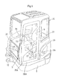
- numeral 1 denotes a backhoe exemplifying a work machine (swivel work machine).
- the backhoe 1 comprises an upper swivel body (upper assembly structure) 2, a propelling apparatus 3 provided downwardly of the swivel body 2, a dozer apparatus 5 acting as an work implement attached to a front portion of the propelling apparatus 3, and an excavating apparatus 7 acting as a work implement attached to the front portion of the swivel body 2.
- the propelling apparatus 3 includes crawler devices 4 mounted on lateral opposite sides thereof.
- Each crawler device 4 has an idler wheel mounted at one side thereof in a fore and aft direction, and a driving wheel mounted at the other side thereof, and a crawler belt wound around a plurality of rollers provided between the idler wheel and the driving wheel.
- the driving wheel of each crawler device 4 is driven by a hydraulically operated propelling motor.
- the dozer apparatus 5 is attached to the front portion of the propelling apparatus 3 to be vertically pivotable by a dozer cylinder including a hydraulic cylinder.
- the swivel body 2 is supported on the propelling apparatus 3 to swivel about a vertical axis X.
- the swivel body 2 includes a swivel deck 6 (vehicle body) 6 to swivel sideways by a hydraulically operated swivel motor.
- a driver's seat 8 is mounted on the swivel body 2 at a substantially mid portion thereof in the fore-and-aft direction, and an engine compartment ER is provided in a rear portion of the swivel deck 6.
- An engine E, a hydraulic pump P, a radiator L, an oil cooler M, and an air cleaner N are accommodated in the engine compartment ER.
- a front-and-rear partition 27 is provided between the engine compartment ER and the driver's seat 8.
- a tank compartment TR is provided in one lateral side (right side) of the swivel deck 6 for accommodating an oil tank (tank) T, a control valve Q, batteries and the like.
- a side partition 26 is provided between the tank compartment TR and the driver's seat 8.
- the control valve Q is attached to a front surface of the oil tank T.
- the excavating apparatus 7 is attached to the front portion of the swivel deck 6.
- a counter weight W is mounted, in addition to the engine E, on a rear portion of the swivel deck 6 in order to strike a weight balance between the swivel deck 6 and the excavating apparatus 7.
- the excavating apparatus 7 includes a support bracket 12 and a pivotable bracket 13.
- the support bracket 12 is fixed to the front portion of the swivel deck 6 while the pivotable bracket 13 is supported to the support bracket 12 to be pivotable sideways about a vertical axis.
- the pivotable bracket 13 swings sideways by a hydraulically operated cylinder.
- the excavating apparatus 7 includes a boom 14 supported to the pivotable bracket 13 to be vertically pivotable, an arm 15 pivotably supported at a proximal end thereof to a distal end of the boom 14, and a bucket 16 attached to a distal end of the arm 15 for scooping and dumping operations.
- the boom, the arm, and the bucket are activated by a boom cylinder 17, an arm cylinder 18, and a bucket cylinder 19, respectively.
- the boom cylinder 17, the arm cylinder 18, and the bucket cylinder 19 are constituted by hydraulic cylinders, for example.
- An operator's section S mounted on the swivel deck 6 is partitioned by the partitions, that is, the front-and-rear partition 27 and the side partition 26.
- the driver's seat 8 is arranged forward of the front-and-rear partition 27 and leftward of the side partition 26.
- a pair of right and left propelling control levers SR and SL are arranged forward of the driver's seat 8 for controlling the right and left crawler devices 4, separately or simultaneously.
- Pedals are provided around the operator's right and left feet.
- a cabin 20 surrounding the operator's section S is mounted on the swivel deck 6.
- the cabin 20 is defined by the front-and-rear partition 27 at a lower rear portion thereof. Although a right wall of the cabin 20 is present, the side partition 26 may also be used as the right wall of the cabin.
- An opening and closing door 20A is provided at an entrance 20a of the cabin 20.
- a two-column type ROPS or a four-column type canopy (acting as a protection device with a sunshade for a driver's seat) may be employed.
- a pair of vertical side walls 6B extending to widen rearward from the support brackets 12 and an intermediate wall 6C partitioning the swivel deck into a front part and a rear part are provided upright on a top surface of a pedestal 6A acting as a bottom of the swivel deck 6.
- the engine E is mounted rearwardly of the intermediate wall 6C through a mounting attachment.
- the engine compartment ER accommodating the engine E, the hydraulic pump P, the air cleaner N and the like is partitioned at a front side thereof by the front-and-rear partition 27 extending upright from the intermediate wall 6C, and is covered by a hood 28 at a rear side and by a left cover member 29 at a left side thereof, for example.
- Reference sign U shown in Figs, 2 and 5 denotes a fuel tank that may be arranged in the tank compartment TR. Instead, in this embodiment, the fuel tank is mounted on the pedestal 6A under a step surface located at a lower left position of the driver's seat 8.
- the fuel tank U has a fuel inlet Ua extending through the front-and-rear partition 27 to the left cover member 29.
- the tank compartment TR mounted on the right side of the swivel deck 6 accommodating the oil tank T, the control valve Q, the radiator L and the like is partitioned at a left side thereof by the side partition 26 fixed at a position adjacent to the driver's seat 8, and is covered by a tank cover member 30 at an upper side, a front side, and a right side thereof.
- Both the engine compartment ER and the tank compartment TR are arranged to form a substantially L-shape as viewed from the top and communicate with each other in the interior.
- the hood 28 and the tank cover member 30 are opened to expose most part of the components mounted on the swivel deck 6 at the side portions thereof, which allows inspection and maintenance.
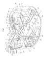
- a four-column type support frame Y is provided within the engine compartment ER to extend across the engine E.
- the support frame Y includes a backbone member 33 positioned above the engine E, a pair of right and left front leg members 34 and 35 and a pair of right and left rear leg members 36 and 37 extending downward from the backbone member 33 at front and rear portions thereof to be fixed to the swivel deck 6, and an arm member 38 extending forward from an end portion of the backbone member 33 adjacent to the tank T.
- the backbone member 33 is formed of a rectangular flat plate, and covered by an upper rear portion of the front-and-rear partition 27, and provided with an attaching portion 33A formed therein to receive a rear portion of the cabin 20 (or a rear post or posts of the two-column type ROPS or the four-column type canopy).
- a stay 33B for detachably fixing an upper portion of the left cover member 29, and a stay 33C for receiving an upper portion of a pivotal support member 40 for pivotably supporting the hood 28.
- the pivotal support member 40 has a fixed piece 40A connected to a swing piece 40B through a vertical shaft 40C to be pivotable about a vertical axis.
- the fixed piece 40A is fixed to the stay 33C of the backbone member 33 at an upper portion thereof and fixedly connected to the counter weight W (or the pedestal 6A) at a lower portion thereof through a stay Wa.
- the swing piece 40B is connected at a free end thereof to a left side end of the hood 28.
- the swing piece 40B has a U-shape as viewed from the top so as to allow the hood 28 to be opened outwardly of the left cover member 29.
- An opening 40Ba is formed in a vertical intermediate portion of the swing piece 40B so as to avoid collision with the air cleaner N supported to the left end of the backbone member 33 or the left front leg member 34, that is to say, so as to allow the swing piece 40B to be pivoted to a position to overlap the air cleaner N when the hood 28 is closed.
- each of the left front leg member 34, the left rear leg member 36, and the right rear leg member 37 is formed of a bent band plate.
- the arm member 38 is formed of a band plate.
- the right front leg member 35 is formed of a square bar (or band plate).
- the left front leg member 34 is secured to a left end of the backbone member 33 at an upper portion thereof, and fixed to a left front stay 6a secured to the intermediate wall 6C at a lower portion thereof.
- An opening cover 31 is attached to the left front leg member 34.
- the opening cover 31 is adapted to close the opening formed in the front-and-rear partition 27 through which the fuel inlet Ua of the fuel tank U extends in order to prevent hot air from flowing into the driver's seat 8 from the engine compartment ER.
- the opening cover 31 is arranged at a rear side of the front-and-rear partition 27.
- the left rear leg member 36 is secured to a lateral intermediate portion of the backbone member 33 at an upper portion thereof, and fixed to a left rear stay 6b mounted upright on the pedestal 6A at a lower portion thereof.
- the right front leg member 35 is secured to a fore-and-aft intermediate portion of the arm member 38 at an upper portion thereof, and fixed to a right front stay 6c secured to the intermediate wall 6C at a lower portion thereof.
- the right rear leg member 37 is secured to a right end of the backbone member 33 at an upper portion thereof, and fixed to a right rear stay 6d mounted upright on the pedestal 6A at a lower portion thereof.
- the arm member 38 is secured to the right end of the backbone member 33 at a rear end thereof.
- a front end of the arm member 38 terminates as a free end around the oil tank T beyond the right front leg member 35.
- An attachment member 38a is mounted on the free end of the arm member 38 to receive an upper portion of the oil tank T through an L-shaped tank bracket 42.
- the oil tank T is fixed in place to a tank seat 43 fixed to the pedestal 6A of the swivel deck 6 at a lower portion thereof. Since the oil tank T is fixed to the tank seat 43 at the lower portion thereof while being fixed to the support frame Y at an upper portion thereof through the tank bracket 42, the attachment strength is enhanced. Thus, even if an impact is applied to the swivel deck 6, vibrations can be minimized, and the number of the attachment bolts needed to attach the tank to the tank seat 43 can be reduced.
- a hinge 44 having a fore-and-aft axis is provided on a top surface of the arm member 38 in a portion hidden by a flange 26a of the side partition 26.
- the tank cover 30 is attached to the hinge 44.
- the tank cover 30 may be a one-piece member, but includes two members, that is, an upper member 30A and a side member 30B in the present embodiment.
- the upper member 30A is made of a resin material and fixed to the hinge 44.
- the side member 30B is made of sheet metal and connected to the upper member 30A through a plurality of connecting elements 45A and 45B, for example, including front, rear, and intermediate connecting elements.
- the side partition 26 is connected to the swivel deck 6 through a stay at a lower portion thereof, connected to a right part of the support frame Y, that is, the right end of the backbone member 33, and the arm member 38, for example, at a rear upper portion thereof through a stay 47.
- a cover receiving member 41 is attached to the rear side of the right rear leg member 37 in a rearward extension of the side partition 26 through the stay 47.
- the cover receiving member 41 is made of sheet metal and has a stepwise shape in section.
- the cover receiving member 41 includes a receiving rear surface 41A contacting a free end (right end) of the hood 28 when closed, and a receiving side surface 41B contacting a rear edge of the tank cover member 30 adjacent to the pivotal support portion thereof when closed, which allows a joint portion between the hood 28 and the tank cover member 30 to be sealed to prevent hot air and noise from leaking to the outside from the engine compartment.
- a shutter plate 48 is fixed between the right front leg member 35 and the right rear leg members 37 under the backbone member 33 and the arm member 38.
- a pair of front and rear retainer 49 are fixed to the shutter plate 48, through which the radiator L and the oil cooler M is fixed at upper portions thereof.
- the radiator L is fixed to the swivel deck 6 at a lower portion thereof and includes a fan shroud arranged adjacent to the engine E.
- the shutter plate 48 and other shutter members are adapted to close between the fan shroud and the backbone member 33, the arm member 38, and the right front and rear leg members 35 and 37, thereby separating those members to prevent air flowing from the radiator L toward the engine E from flowing backward from the engine E toward the radiator L as hot air.
- the cover receiving member 41 also acts as such a partition.
- the support frame Y supports directly or indirectly the external parts including the side partition 26, the front-and-rear partition 27, the hood 28, the left cover member 29, the tank cover member 30, the opening cover 31 and the cover receiving member 41, the shutter plate 48, and the cabin 20 (or a ROPS or a canopy), and the internal equipment including the air cleaner N, the oil tank T, the radiator L, and the oil cooler M.
- the support frame Y has the arm member 38 protruding toward the tank compartment TR, which allows the oil tank T and the tank cover member 30 to be supported thereto. Since those members are supported concentratedly by the support frame Y, the mounting positions of those members relative to the swivel deck 6 and relative to one another can be maintained constant. This facilitates dimension control for the gaps and the degree of overlapping between the components to enhance the assembling accuracy.
- Figs. 1 to 11 show the best mode of the shapes of the components and the positional relationships between the components with respect to the fore-and-aft direction, the transverse direction, and the vertical direction in accordance with the present invention.
- the present invention is not limited to the embodiment noted above, but the components, their arrangements, and their combinations can be variously modified.
- the backhoe 1 includes the tank compartment TR for the oil tank T and the like arranged at the right side of the swivel deck 6.
- the tank compartment may be arranged at the left side of the swivel deck 6 so that the positions of the oil tank T and the driver's seat 8, or the positions of right and left control devices 22 and 23 may be reversed.
- the support frame Y may include the left rear leg member 36 and the left front leg member 34 that are formed by bending a single band plate.
- the four-column construction may be a three-column construction omitting the left rear leg member 36.
- left rear leg member 36 may be connected to the left end of the backbone member 33, while the pivotal support member 40 for pivotably supporting the hood 28 may be fixed to the backbone member 33 and the left rear leg member 36.
Landscapes
- Engineering & Computer Science (AREA)
- Mining & Mineral Resources (AREA)
- Civil Engineering (AREA)
- General Engineering & Computer Science (AREA)
- Structural Engineering (AREA)
- Chemical & Material Sciences (AREA)
- Combustion & Propulsion (AREA)
- Transportation (AREA)
- Mechanical Engineering (AREA)
- Component Parts Of Construction Machinery (AREA)
- Body Structure For Vehicles (AREA)
- Superstructure Of Vehicle (AREA)
Applications Claiming Priority (1)
| Application Number | Priority Date | Filing Date | Title |
|---|---|---|---|
| JP2008090094A JP4686565B2 (ja) | 2008-03-31 | 2008-03-31 | 作業機の上部構造 |
Publications (3)
| Publication Number | Publication Date |
|---|---|
| EP2107168A2 true EP2107168A2 (de) | 2009-10-07 |
| EP2107168A3 EP2107168A3 (de) | 2013-10-02 |
| EP2107168B1 EP2107168B1 (de) | 2016-10-19 |
Family
ID=40668137
Family Applications (1)
| Application Number | Title | Priority Date | Filing Date |
|---|---|---|---|
| EP09154252.2A Active EP2107168B1 (de) | 2008-03-31 | 2009-03-03 | Obere Baugruppenstruktur einer Bearbeitungsmaschine |
Country Status (5)
| Country | Link |
|---|---|
| US (1) | US8083019B2 (de) |
| EP (1) | EP2107168B1 (de) |
| JP (1) | JP4686565B2 (de) |
| KR (1) | KR101098140B1 (de) |
| CN (1) | CN101550711B (de) |
Families Citing this family (13)
| Publication number | Priority date | Publication date | Assignee | Title |
|---|---|---|---|---|
| US8262149B1 (en) * | 2008-08-26 | 2012-09-11 | William Russ | Fan and canopy assembly for riding vehicle |
| JP5061085B2 (ja) * | 2008-11-17 | 2012-10-31 | 株式会社クボタ | 旋回作業機のボンネットシール構造 |
| JP5599758B2 (ja) * | 2011-05-19 | 2014-10-01 | 日立建機株式会社 | 開口閉塞カバーおよび該開口閉塞カバーを備えた建設機械 |
| DE112013000122B4 (de) * | 2013-02-15 | 2017-06-14 | Komatsu Ltd. | Hydraulikbagger |
| DE102013004347A1 (de) * | 2013-03-14 | 2014-09-18 | Jungheinrich Aktiengesellschaft | Flurförderzeug mit einem Fahrerschutzdach |
| JP5819891B2 (ja) * | 2013-08-21 | 2015-11-24 | 日立建機株式会社 | 建設機械 |
| JP6040187B2 (ja) * | 2014-02-24 | 2016-12-07 | 日立建機株式会社 | 建設機械 |
| JP6938432B2 (ja) * | 2017-07-18 | 2021-09-22 | 株式会社クボタ | 作業機 |
| US11007842B2 (en) * | 2018-02-02 | 2021-05-18 | William Russ | Fan and canopy assembly for riding vehicle |
| EP4406780A3 (de) * | 2019-06-26 | 2025-01-08 | Kubota Corporation | Arbeitsmaschine |
| JP7644742B2 (ja) * | 2022-10-21 | 2025-03-12 | 株式会社竹内製作所 | 作業用車両 |
| JP2024092771A (ja) * | 2022-12-26 | 2024-07-08 | 株式会社クボタ | 作業機 |
| EP4675052A1 (de) | 2024-07-03 | 2026-01-07 | Yanmar Holdings Co., Ltd. | Arbeitsmaschine |
Citations (2)
| Publication number | Priority date | Publication date | Assignee | Title |
|---|---|---|---|---|
| JP2003064724A (ja) | 2001-08-28 | 2003-03-05 | Kubota Corp | 旋回作業機 |
| JP2006274598A (ja) | 2005-03-28 | 2006-10-12 | Kubota Corp | 旋回作業機 |
Family Cites Families (19)
| Publication number | Priority date | Publication date | Assignee | Title |
|---|---|---|---|---|
| JP3572719B2 (ja) * | 1995-05-16 | 2004-10-06 | コベルコ建機株式会社 | 油圧作業機 |
| JP3155463B2 (ja) * | 1996-05-28 | 2001-04-09 | 株式会社クボタ | 作業機の支持フレーム構造 |
| JP3645400B2 (ja) | 1997-06-03 | 2005-05-11 | 日立建機株式会社 | 旋回式建設機械 |
| EP1162318A1 (de) * | 2000-06-06 | 2001-12-12 | Deere & Company | Mehrzweckkasten für ein Arbeitsfahrzeug |
| US7523804B2 (en) * | 2002-03-26 | 2009-04-28 | Kobelco Construction Machinery Co., Ltd. | Small swing type shovel |
| JP4211919B2 (ja) * | 2003-03-24 | 2009-01-21 | 株式会社小松製作所 | 油圧ショベルのカウンタウエイト |
| JP2005014642A (ja) * | 2003-06-23 | 2005-01-20 | Hitachi Constr Mach Co Ltd | 建設機械 |
| JP3956907B2 (ja) * | 2003-06-24 | 2007-08-08 | コベルコ建機株式会社 | 小型ショベル |
| JP4133899B2 (ja) * | 2004-03-29 | 2008-08-13 | 株式会社クボタ | 旋回作業機 |
| JP4226546B2 (ja) * | 2004-03-29 | 2009-02-18 | 株式会社クボタ | 旋回作業機 |
| JP4515232B2 (ja) * | 2004-11-22 | 2010-07-28 | 株式会社クボタ | 旋回作業機 |
| JP4134013B2 (ja) | 2004-12-03 | 2008-08-13 | 株式会社クボタ | 旋回作業機の後上部支持フレーム構造 |
| JP4619169B2 (ja) | 2005-03-28 | 2011-01-26 | 株式会社クボタ | 旋回作業機 |
| JP4619168B2 (ja) * | 2005-03-28 | 2011-01-26 | 株式会社クボタ | 旋回作業機 |
| JP2007138406A (ja) * | 2005-11-15 | 2007-06-07 | Shin Caterpillar Mitsubishi Ltd | 作業機械の開閉式カバーの断熱構造 |
| CN2911021Y (zh) * | 2005-12-09 | 2007-06-13 | 柳州市华力实业有限责任公司 | 建筑机械驾驶室外壳框架 |
| CN2892983Y (zh) * | 2005-12-09 | 2007-04-25 | 柳州市华力实业有限责任公司 | 驾驶室翻转装置及带该装置的挖掘机翻转式驾驶室 |
| ATE522671T1 (de) * | 2006-11-28 | 2011-09-15 | Hitachi Construction Machinery | Baumaschine |
| JP5061085B2 (ja) * | 2008-11-17 | 2012-10-31 | 株式会社クボタ | 旋回作業機のボンネットシール構造 |
-
2008
- 2008-03-31 JP JP2008090094A patent/JP4686565B2/ja active Active
-
2009
- 2009-03-03 KR KR1020090017809A patent/KR101098140B1/ko active Active
- 2009-03-03 EP EP09154252.2A patent/EP2107168B1/de active Active
- 2009-03-05 US US12/398,414 patent/US8083019B2/en active Active
- 2009-03-31 CN CN2009101325122A patent/CN101550711B/zh active Active
Patent Citations (2)
| Publication number | Priority date | Publication date | Assignee | Title |
|---|---|---|---|---|
| JP2003064724A (ja) | 2001-08-28 | 2003-03-05 | Kubota Corp | 旋回作業機 |
| JP2006274598A (ja) | 2005-03-28 | 2006-10-12 | Kubota Corp | 旋回作業機 |
Also Published As
| Publication number | Publication date |
|---|---|
| CN101550711A (zh) | 2009-10-07 |
| US8083019B2 (en) | 2011-12-27 |
| KR101098140B1 (ko) | 2011-12-26 |
| JP2009243119A (ja) | 2009-10-22 |
| CN101550711B (zh) | 2011-11-16 |
| US20090242311A1 (en) | 2009-10-01 |
| EP2107168B1 (de) | 2016-10-19 |
| JP4686565B2 (ja) | 2011-05-25 |
| EP2107168A3 (de) | 2013-10-02 |
| KR20090104660A (ko) | 2009-10-06 |
Similar Documents
| Publication | Publication Date | Title |
|---|---|---|
| EP2107168B1 (de) | Obere Baugruppenstruktur einer Bearbeitungsmaschine | |
| US7481289B2 (en) | Swiveling work machine | |
| EP1589153B1 (de) | Drehbare Arbeitsmaschine mit einem schwenkbaren Oberbau | |
| US8545163B2 (en) | Loader work machine | |
| US8342277B2 (en) | Mounting arrangement for mounting cooler unit to work machine | |
| CN1965131B (zh) | 施工车辆 | |
| US7188865B2 (en) | Counterweight for hydraulic shovel | |
| US7717218B2 (en) | Swiveling work machine | |
| CN105814260B (zh) | 液压挖掘机 | |
| KR20070037673A (ko) | 작업 기계 | |
| JPH07207702A (ja) | バックホウのボンネット構造 | |
| JP5546822B2 (ja) | 建設機械 | |
| JPS6322199Y2 (de) | ||
| JP2007046233A (ja) | 建設機械 | |
| JP4619170B2 (ja) | 旋回作業機 | |
| JP3393987B2 (ja) | 旋回作業機 | |
| JP2026053935A (ja) | 作業機械 | |
| JP6738482B2 (ja) | 建設機械 | |
| JP2024117974A (ja) | 作業機械 | |
| JP2026053933A (ja) | 作業機械 | |
| WO2025187321A1 (ja) | カメラ、カメラの固定構造、作業機 | |
| JP4544514B2 (ja) | 建設機械用キャブ | |
| JPH11269936A (ja) | 旋回作業機 | |
| JP2022011615A (ja) | 作業機 | |
| JP2000291063A (ja) | 旋回式建設機械 |
Legal Events
| Date | Code | Title | Description |
|---|---|---|---|
| PUAI | Public reference made under article 153(3) epc to a published international application that has entered the european phase |
Free format text: ORIGINAL CODE: 0009012 |
|
| 17P | Request for examination filed |
Effective date: 20090327 |
|
| AK | Designated contracting states |
Kind code of ref document: A2 Designated state(s): AT BE BG CH CY CZ DE DK EE ES FI FR GB GR HR HU IE IS IT LI LT LU LV MC MK MT NL NO PL PT RO SE SI SK TR |
|
| AX | Request for extension of the european patent |
Extension state: AL BA RS |
|
| PUAL | Search report despatched |
Free format text: ORIGINAL CODE: 0009013 |
|
| AK | Designated contracting states |
Kind code of ref document: A3 Designated state(s): AT BE BG CH CY CZ DE DK EE ES FI FR GB GR HR HU IE IS IT LI LT LU LV MC MK MT NL NO PL PT RO SE SI SK TR |
|
| AX | Request for extension of the european patent |
Extension state: AL BA RS |
|
| RIC1 | Information provided on ipc code assigned before grant |
Ipc: B62D 33/063 20060101ALI20130829BHEP Ipc: B62D 33/06 20060101ALI20130829BHEP Ipc: E02F 9/08 20060101AFI20130829BHEP |
|
| RBV | Designated contracting states (corrected) |
Designated state(s): AT BE BG CH CY CZ DE DK EE ES FI FR GB GR HR HU IE IS IT LI LT LU LV MC MK MT NL NO PL PT RO SE SI SK TR |
|
| 17Q | First examination report despatched |
Effective date: 20140430 |
|
| AKX | Designation fees paid |
Designated state(s): DE FR GB IT |
|
| GRAP | Despatch of communication of intention to grant a patent |
Free format text: ORIGINAL CODE: EPIDOSNIGR1 |
|
| INTG | Intention to grant announced |
Effective date: 20160317 |
|
| RIN1 | Information on inventor provided before grant (corrected) |
Inventor name: FUJIWARA, JUNICHI Inventor name: MUKAE, SHINYA Inventor name: FUJITA, YUJI |
|
| GRAJ | Information related to disapproval of communication of intention to grant by the applicant or resumption of examination proceedings by the epo deleted |
Free format text: ORIGINAL CODE: EPIDOSDIGR1 |
|
| INTC | Intention to grant announced (deleted) | ||
| GRAR | Information related to intention to grant a patent recorded |
Free format text: ORIGINAL CODE: EPIDOSNIGR71 |
|
| GRAS | Grant fee paid |
Free format text: ORIGINAL CODE: EPIDOSNIGR3 |
|
| GRAA | (expected) grant |
Free format text: ORIGINAL CODE: 0009210 |
|
| AK | Designated contracting states |
Kind code of ref document: B1 Designated state(s): DE FR GB IT |
|
| INTG | Intention to grant announced |
Effective date: 20160914 |
|
| REG | Reference to a national code |
Ref country code: GB Ref legal event code: FG4D |
|
| REG | Reference to a national code |
Ref country code: DE Ref legal event code: R096 Ref document number: 602009041792 Country of ref document: DE |
|
| REG | Reference to a national code |
Ref country code: DE Ref legal event code: R097 Ref document number: 602009041792 Country of ref document: DE |
|
| PLBE | No opposition filed within time limit |
Free format text: ORIGINAL CODE: 0009261 |
|
| STAA | Information on the status of an ep patent application or granted ep patent |
Free format text: STATUS: NO OPPOSITION FILED WITHIN TIME LIMIT |
|
| PG25 | Lapsed in a contracting state [announced via postgrant information from national office to epo] |
Ref country code: IT Free format text: LAPSE BECAUSE OF FAILURE TO SUBMIT A TRANSLATION OF THE DESCRIPTION OR TO PAY THE FEE WITHIN THE PRESCRIBED TIME-LIMIT Effective date: 20161019 |
|
| 26N | No opposition filed |
Effective date: 20170720 |
|
| GBPC | Gb: european patent ceased through non-payment of renewal fee |
Effective date: 20170303 |
|
| REG | Reference to a national code |
Ref country code: FR Ref legal event code: ST Effective date: 20171130 |
|
| PG25 | Lapsed in a contracting state [announced via postgrant information from national office to epo] |
Ref country code: FR Free format text: LAPSE BECAUSE OF NON-PAYMENT OF DUE FEES Effective date: 20170331 |
|
| PG25 | Lapsed in a contracting state [announced via postgrant information from national office to epo] |
Ref country code: GB Free format text: LAPSE BECAUSE OF NON-PAYMENT OF DUE FEES Effective date: 20170303 |
|
| PGFP | Annual fee paid to national office [announced via postgrant information from national office to epo] |
Ref country code: DE Payment date: 20260128 Year of fee payment: 18 |