EP2107193A2 - Dispositif de réglage pour fenêtres, portes ou autres éléments d'ouverture - Google Patents
Dispositif de réglage pour fenêtres, portes ou autres éléments d'ouvertureInfo
- Publication number
- EP2107193A2 EP2107193A2 EP09152122A EP09152122A EP2107193A2 EP 2107193 A2 EP2107193 A2 EP 2107193A2 EP 09152122 A EP09152122 A EP 09152122A EP 09152122 A EP09152122 A EP 09152122A EP 2107193 A2 EP2107193 A2 EP 2107193A2
- Authority
- EP
- European Patent Office
- Prior art keywords
- locking device
- wing
- holding means
- balls
- locking
- Prior art date
- Legal status (The legal status is an assumption and is not a legal conclusion. Google has not performed a legal analysis and makes no representation as to the accuracy of the status listed.)
- Withdrawn
Links
- 238000005096 rolling process Methods 0.000 claims description 10
- 238000004519 manufacturing process Methods 0.000 description 1
Images

Classifications
-
- E—FIXED CONSTRUCTIONS
- E05—LOCKS; KEYS; WINDOW OR DOOR FITTINGS; SAFES
- E05C—BOLTS OR FASTENING DEVICES FOR WINGS, SPECIALLY FOR DOORS OR WINDOWS
- E05C17/00—Devices for holding wings open; Devices for limiting opening of wings or for holding wings open by a movable member extending between frame and wing; Braking devices, stops or buffers, combined therewith
- E05C17/02—Devices for holding wings open; Devices for limiting opening of wings or for holding wings open by a movable member extending between frame and wing; Braking devices, stops or buffers, combined therewith by mechanical means
- E05C17/04—Devices for holding wings open; Devices for limiting opening of wings or for holding wings open by a movable member extending between frame and wing; Braking devices, stops or buffers, combined therewith by mechanical means with a movable bar or equivalent member extending between frame and wing
- E05C17/12—Devices for holding wings open; Devices for limiting opening of wings or for holding wings open by a movable member extending between frame and wing; Braking devices, stops or buffers, combined therewith by mechanical means with a movable bar or equivalent member extending between frame and wing consisting of a single rod
- E05C17/24—Devices for holding wings open; Devices for limiting opening of wings or for holding wings open by a movable member extending between frame and wing; Braking devices, stops or buffers, combined therewith by mechanical means with a movable bar or equivalent member extending between frame and wing consisting of a single rod pivoted at one end, and with the other end running along a guide member
- E05C17/26—Devices for holding wings open; Devices for limiting opening of wings or for holding wings open by a movable member extending between frame and wing; Braking devices, stops or buffers, combined therewith by mechanical means with a movable bar or equivalent member extending between frame and wing consisting of a single rod pivoted at one end, and with the other end running along a guide member with braking, clamping or securing means at the pivot of the rod
Definitions
- the present invention relates to a locking device for windows, doors or other opening elements, with a fixed frame on which a wing is movably supported, wherein locking means are provided to fix the wing in different open positions relative to the frame.
- the DE 195 16 588 discloses a locking device for windows or doors, in which a fitting is provided between a fixed frame and a movable wing, in which a Ausstellarm is guided on a rail via a slider.
- a profiling is formed on the slide, which is positively inserted into an adjacent profiling of a bar.
- the slider is raised perpendicular to the direction to move him either during movement of the wing or press to fix the wing in the profiling on the bar.
- Such a locking device must be adapted to the proportions of the wing and the frame.
- numerous components are required, which make both the assembly and the production consuming.
- the EP 380 440 discloses a wing closure for a window or a door, in which, in addition to the open position and the closed position, a further opening position of the wing is provided, in which it can be fixed. For this is provided a handle which makes a detent over various fitting parts. However, it is not possible to fix the wing in any angular positions.
- the locking means comprise a circulation element which is coupled to a fitting part and which can be fixed via a retaining element.
- the circulation element can be moved when opening the wing until a fixation is to take place, for which purpose a corresponding holding means cooperates with the circulating element.
- the holding means engages for fixing in the circulation element.
- a secure hold of the wing is achieved in the desired opening position.
- the circulation element comprises a plurality of rolling elements, such as balls, cylinders or tons, which are guided in a revolving path.
- the fitting part can be coupled with a slider, which is arranged between the rolling elements.
- the rolling elements can be moved circumferentially in the path via a movement of the sliding body.
- the holding means may be formed as a stop, which can be inserted into the revolving path, so that then the movement of the rolling elements is interrupted. These are then no longer movable within the tracks by the slider.
- the stop can be designed rod-shaped and pass through the encircling path to set the rolling elements, so that high forces can be absorbed by the locking means.
- the revolving track can be mounted in a compact design in a wing.
- the holding means is movable via a handle arranged on the wing. This allows mechanical fixing of the wing via the handle.
- actuate the holding means via a drive, for example via an electric drive, which is also remotely controlled or connected to a central control.
- the circulating element is designed as a band, rope or chain. These peripherally formed elements can be fixed by appropriate retaining means.
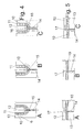
- a window 1 or a door comprises a frame 2, on which a wing 3 is movably held.
- the wing 3 is at least pivotable about an axis of rotation 4 stored and can be operated via a handle element 5.
- Figure 1A the wing 3 is arranged in the closed position.
- FIGS. 1B, 2B, 3B each show the associated handle positions to the Figures 1A, 2A and 3A ,
- the handle 5 is rotated by 90 °, so that a lock with the frame 2 is released and the wing 3 can be pivoted to an open position.
- locking means 5 are provided in order to fix the wing 3 in any opening positions can.
- a stay 7 at one end 8 fixed and rotatably connected to the frame 2.
- An opposite end of the stay 7 is fixed to the locking means 6.
- the locking means 6 are fixed on the handle 5, wherein the wing 3 in the in FIG. 2B shown position of the handle 5 is pivotable.
- FIG. 3A the wing 3 is shown in an open position (X degrees), in which the locking means 6 set the wing 3.
- the handle 5 from the position in FIG. 2B be further pivoted ( FIG. 3B ) to operate the locking means 6.
- An opposite rotation of the handle 5 for fixing the locking means 6 is possible (dashed line in FIG FIG. 3B ).
- the locking means 6 are shown in detail, wherein no fixing of the wing 3 takes place.
- the locking means 6 comprise a housing in which a circumferential track 11 is formed, in which a plurality of balls 10 are guided circumferentially.
- the web 11 is bounded on the outside by a wall 13 and internally by a wall 12, so that the balls 10 can only be moved in the loop-shaped path 11.
- a sliding element 9 is provided at a position which is arranged as a ball cage or as another sliding element between the balls 10.
- a holding means 14 is provided on the locking means 6, which is formed as an elongated rod and a tip 15 comprises.
- the rod-shaped holding means 14 is in the web 11th introduced with the balls 10, as shown in FIG. 4B is shown.
- the tip 15 optionally pushes balls 10 which are in the way slightly away, so that the rod-shaped holding means 14 can be inserted into a gap between two balls 10.
- the rod-shaped holding means 14 passes through the web 11 and rests with the tip 15 in a receptacle 16 within the inner wall 12 at.
- the holding means 14 serves as a stop, so that the balls 10 can not be moved circumferentially. Since the balls 10 are locked, and the slider 9 can not be moved within the web 11, so that a relative movement of the stay 7 to the wing 3 is no longer possible.
- the wing 3 can thus be fixed at short intervals by the holding means 14.
- the holding means 14 can be actuated via the handle 5.
- FIGS. 5A to 5C a modified embodiment of a locking means 6 is shown in which the holding means 14 is not arranged on a deflection of the web 11 for the rollers, but along a straight line. Again, the rod-shaped holding means 14 is inserted into the web 11 with the balls 10 for locking the wing 3 until the web 11 is penetrated. The rod-shaped holding means 14 is held on the opposite wall 12 in a receptacle 17.
- the length of the track 11 with the balls 10 can be selected depending on the size of the opening movement.
- the holding means 14 is actuated by turning the handle 5. It is of course also possible to perform the operation not via the handle 5 but via other mechanical actuating means.
- a fixing of the wing can also take place via a drive which moves the holding means 14. This drive can then be actuated via a controller that can output corresponding control commands via a bus system or a remote control.
- the circulating element is formed in the embodiments shown by a plurality of balls 10, which are guided in a revolving path 11. It is also possible to provide as a revolving element a band, rope or chain. This can also be fixed by a holding means, for example, when the tape is pierced, the rope has recordings or in the distances between the chain links.
Landscapes
- Engineering & Computer Science (AREA)
- Mechanical Engineering (AREA)
- Closing And Opening Devices For Wings, And Checks For Wings (AREA)
- Wing Frames And Configurations (AREA)
Applications Claiming Priority (1)
| Application Number | Priority Date | Filing Date | Title |
|---|---|---|---|
| DE202008004660U DE202008004660U1 (de) | 2008-04-04 | 2008-04-04 | Feststellvorrichtung für Fenster, Türen oder andere Öffnungselemente |
Publications (2)
| Publication Number | Publication Date |
|---|---|
| EP2107193A2 true EP2107193A2 (fr) | 2009-10-07 |
| EP2107193A3 EP2107193A3 (fr) | 2011-07-20 |
Family
ID=40785619
Family Applications (1)
| Application Number | Title | Priority Date | Filing Date |
|---|---|---|---|
| EP09152122A Withdrawn EP2107193A3 (fr) | 2008-04-04 | 2009-02-05 | Dispositif de réglage pour fenêtres, portes ou autres éléments d'ouverture |
Country Status (2)
| Country | Link |
|---|---|
| EP (1) | EP2107193A3 (fr) |
| DE (1) | DE202008004660U1 (fr) |
Families Citing this family (1)
| Publication number | Priority date | Publication date | Assignee | Title |
|---|---|---|---|---|
| DE102013112226A1 (de) * | 2013-11-06 | 2015-05-07 | Sapa Building Systems GmbH | Beschlag |
Citations (2)
| Publication number | Priority date | Publication date | Assignee | Title |
|---|---|---|---|---|
| EP0380440A1 (fr) | 1989-01-25 | 1990-08-01 | Usm U. Schaerer Soehne Ag | Porte ou fenêtre |
| DE19516588C1 (de) | 1995-05-05 | 1996-09-19 | Weidtmann Wilhelm Kg | Feststellvorrichtung für Fenster, Türen od. dgl. |
Family Cites Families (4)
| Publication number | Priority date | Publication date | Assignee | Title |
|---|---|---|---|---|
| GB483104A (en) * | 1937-01-07 | 1938-04-12 | James Henry Bennetts | An improved combined door stop and catch |
| GB518416A (en) * | 1938-08-24 | 1940-02-27 | Frederick William Wilson | Improvements in or relating to fastening, fixing and regulating devices or stays for hinged windows, windscreens, and the like |
| US2832590A (en) * | 1955-11-09 | 1958-04-29 | H B Ives Company | Casement window operators |
| DE1095709B (de) * | 1958-03-26 | 1960-12-22 | Wilhelm Frank | Umlenkvorrichtung fuer Fenster- oder Tuerbeschlagteile, insbesondere fuer Betaetigungs- und Riegelstangen |
-
2008
- 2008-04-04 DE DE202008004660U patent/DE202008004660U1/de not_active Expired - Lifetime
-
2009
- 2009-02-05 EP EP09152122A patent/EP2107193A3/fr not_active Withdrawn
Patent Citations (2)
| Publication number | Priority date | Publication date | Assignee | Title |
|---|---|---|---|---|
| EP0380440A1 (fr) | 1989-01-25 | 1990-08-01 | Usm U. Schaerer Soehne Ag | Porte ou fenêtre |
| DE19516588C1 (de) | 1995-05-05 | 1996-09-19 | Weidtmann Wilhelm Kg | Feststellvorrichtung für Fenster, Türen od. dgl. |
Also Published As
| Publication number | Publication date |
|---|---|
| EP2107193A3 (fr) | 2011-07-20 |
| DE202008004660U1 (de) | 2009-08-13 |
Similar Documents
| Publication | Publication Date | Title |
|---|---|---|
| EP1247930B1 (fr) | Dispositif d'arrêt pour chariots guidés dans des rails | |
| EP1959080B1 (fr) | Butée de battant mobile de fenêtre ou de porte | |
| DE102004037937B4 (de) | Türschloss, insbesondere mit Panikfunktion | |
| DE4321099C2 (de) | Belüftungseinrichtung für Fenster oder Türen | |
| EP3401475A1 (fr) | Système d'armatures | |
| EP2146032B1 (fr) | Dispositif destiné à ouvrir et/ou fermer ainsi qu'à verrouiller un état fermé d'un dispositif de fermeture destiné à fermer une ouverture de salle ainsi que dispositif de fermeture doté d'un tel dispositif | |
| EP1740792B1 (fr) | Fenetre oscillo-battante | |
| EP3498960B1 (fr) | Dispositif de verrouillage pour une porte, en particulier une porte coulissante | |
| EP3901402B1 (fr) | Agencement de chariot pour une porte coulissante | |
| DE202006013676U1 (de) | Tor, insbesondere Sektionaltor, und Torantriebsvorrichtung | |
| EP0728888A1 (fr) | Loquet à ressort pour porte oscillo-battante | |
| EP1826342B1 (fr) | Ouvrant sectionnel avec porte d'évacuation | |
| EP2107193A2 (fr) | Dispositif de réglage pour fenêtres, portes ou autres éléments d'ouverture | |
| DE19900875C2 (de) | Verriegelungsvorrichtung für eine Türanlage | |
| EP0846825B1 (fr) | Dispositif de verrouillage pour un vantail de porte amovible dans un châssis | |
| WO2009135473A1 (fr) | Porte sectionnelle | |
| EP1128015A2 (fr) | Fenêtre ou porte à coulissement parallèle | |
| DE10127864C1 (de) | Schaltschrank für eine elektrische Schaltanlage mit einer Tür | |
| EP4174266A1 (fr) | Agencement de battant | |
| EP2878749B1 (fr) | Porte sectionnelle dotée d'un agencement de verrouillage | |
| WO2009039899A1 (fr) | Serrure électronique | |
| EP4215704B1 (fr) | Dispositif de blocage, ferrure et agencement du cadre de battant | |
| DE10015095A1 (de) | Verriegelungsvorrichtung für einen Türflügel | |
| EP4219870B1 (fr) | Crochet d'arrêt et dispositif de retenue comprenant un tel crochet d'arrêt | |
| EP2474691B1 (fr) | Porte sectionnelle dotée d'un agencement de verrouillage |
Legal Events
| Date | Code | Title | Description |
|---|---|---|---|
| PUAI | Public reference made under article 153(3) epc to a published international application that has entered the european phase |
Free format text: ORIGINAL CODE: 0009012 |
|
| AK | Designated contracting states |
Kind code of ref document: A2 Designated state(s): AT BE BG CH CY CZ DE DK EE ES FI FR GB GR HR HU IE IS IT LI LT LU LV MC MK MT NL NO PL PT RO SE SI SK TR |
|
| AX | Request for extension of the european patent |
Extension state: AL BA RS |
|
| PUAL | Search report despatched |
Free format text: ORIGINAL CODE: 0009013 |
|
| AK | Designated contracting states |
Kind code of ref document: A3 Designated state(s): AT BE BG CH CY CZ DE DK EE ES FI FR GB GR HR HU IE IS IT LI LT LU LV MC MK MT NL NO PL PT RO SE SI SK TR |
|
| AX | Request for extension of the european patent |
Extension state: AL BA RS |
|
| STAA | Information on the status of an ep patent application or granted ep patent |
Free format text: STATUS: THE APPLICATION IS DEEMED TO BE WITHDRAWN |
|
| AKY | No designation fees paid | ||
| 18D | Application deemed to be withdrawn |
Effective date: 20110830 |
|
| REG | Reference to a national code |
Ref country code: DE Ref legal event code: R108 Effective date: 20120328 |