EP2107283A2 - Dispositif anti-écoulement - Google Patents
Dispositif anti-écoulement Download PDFInfo
- Publication number
- EP2107283A2 EP2107283A2 EP08013000A EP08013000A EP2107283A2 EP 2107283 A2 EP2107283 A2 EP 2107283A2 EP 08013000 A EP08013000 A EP 08013000A EP 08013000 A EP08013000 A EP 08013000A EP 2107283 A2 EP2107283 A2 EP 2107283A2
- Authority
- EP
- European Patent Office
- Prior art keywords
- flooding
- liquid
- passage
- duct
- flooding device
- Prior art date
- Legal status (The legal status is an assumption and is not a legal conclusion. Google has not performed a legal analysis and makes no representation as to the accuracy of the status listed.)
- Withdrawn
Links
Images


Classifications
-
- F—MECHANICAL ENGINEERING; LIGHTING; HEATING; WEAPONS; BLASTING
- F16—ENGINEERING ELEMENTS AND UNITS; GENERAL MEASURES FOR PRODUCING AND MAINTAINING EFFECTIVE FUNCTIONING OF MACHINES OR INSTALLATIONS; THERMAL INSULATION IN GENERAL
- F16K—VALVES; TAPS; COCKS; ACTUATING-FLOATS; DEVICES FOR VENTING OR AERATING
- F16K17/00—Safety valves; Equalising valves, e.g. pressure relief valves
- F16K17/20—Excess-flow valves
- F16K17/22—Excess-flow valves actuated by the difference of pressure between two places in the flow line
- F16K17/24—Excess-flow valves actuated by the difference of pressure between two places in the flow line acting directly on the cutting-off member
- F16K17/28—Excess-flow valves actuated by the difference of pressure between two places in the flow line acting directly on the cutting-off member operating in one direction only
- F16K17/30—Excess-flow valves actuated by the difference of pressure between two places in the flow line acting directly on the cutting-off member operating in one direction only spring-loaded
-
- Y—GENERAL TAGGING OF NEW TECHNOLOGICAL DEVELOPMENTS; GENERAL TAGGING OF CROSS-SECTIONAL TECHNOLOGIES SPANNING OVER SEVERAL SECTIONS OF THE IPC; TECHNICAL SUBJECTS COVERED BY FORMER USPC CROSS-REFERENCE ART COLLECTIONS [XRACs] AND DIGESTS
- Y10—TECHNICAL SUBJECTS COVERED BY FORMER USPC
- Y10T—TECHNICAL SUBJECTS COVERED BY FORMER US CLASSIFICATION
- Y10T137/00—Fluid handling
- Y10T137/7722—Line condition change responsive valves
- Y10T137/7781—With separate connected fluid reactor surface
- Y10T137/7784—Responsive to change in rate of fluid flow
- Y10T137/7785—Valve closes in response to excessive flow
-
- Y—GENERAL TAGGING OF NEW TECHNOLOGICAL DEVELOPMENTS; GENERAL TAGGING OF CROSS-SECTIONAL TECHNOLOGIES SPANNING OVER SEVERAL SECTIONS OF THE IPC; TECHNICAL SUBJECTS COVERED BY FORMER USPC CROSS-REFERENCE ART COLLECTIONS [XRACs] AND DIGESTS
- Y10—TECHNICAL SUBJECTS COVERED BY FORMER USPC
- Y10T—TECHNICAL SUBJECTS COVERED BY FORMER US CLASSIFICATION
- Y10T137/00—Fluid handling
- Y10T137/7722—Line condition change responsive valves
- Y10T137/7837—Direct response valves [i.e., check valve type]
- Y10T137/7838—Plural
- Y10T137/7839—Dividing and recombining in a single flow path
-
- Y—GENERAL TAGGING OF NEW TECHNOLOGICAL DEVELOPMENTS; GENERAL TAGGING OF CROSS-SECTIONAL TECHNOLOGIES SPANNING OVER SEVERAL SECTIONS OF THE IPC; TECHNICAL SUBJECTS COVERED BY FORMER USPC CROSS-REFERENCE ART COLLECTIONS [XRACs] AND DIGESTS
- Y10—TECHNICAL SUBJECTS COVERED BY FORMER USPC
- Y10T—TECHNICAL SUBJECTS COVERED BY FORMER US CLASSIFICATION
- Y10T137/00—Fluid handling
- Y10T137/7722—Line condition change responsive valves
- Y10T137/7837—Direct response valves [i.e., check valve type]
- Y10T137/7838—Plural
- Y10T137/7842—Diverse types
-
- Y—GENERAL TAGGING OF NEW TECHNOLOGICAL DEVELOPMENTS; GENERAL TAGGING OF CROSS-SECTIONAL TECHNOLOGIES SPANNING OVER SEVERAL SECTIONS OF THE IPC; TECHNICAL SUBJECTS COVERED BY FORMER USPC CROSS-REFERENCE ART COLLECTIONS [XRACs] AND DIGESTS
- Y10—TECHNICAL SUBJECTS COVERED BY FORMER USPC
- Y10T—TECHNICAL SUBJECTS COVERED BY FORMER US CLASSIFICATION
- Y10T137/00—Fluid handling
- Y10T137/7722—Line condition change responsive valves
- Y10T137/7837—Direct response valves [i.e., check valve type]
- Y10T137/7838—Plural
- Y10T137/7846—Mechanically interconnected
-
- Y—GENERAL TAGGING OF NEW TECHNOLOGICAL DEVELOPMENTS; GENERAL TAGGING OF CROSS-SECTIONAL TECHNOLOGIES SPANNING OVER SEVERAL SECTIONS OF THE IPC; TECHNICAL SUBJECTS COVERED BY FORMER USPC CROSS-REFERENCE ART COLLECTIONS [XRACs] AND DIGESTS
- Y10—TECHNICAL SUBJECTS COVERED BY FORMER USPC
- Y10T—TECHNICAL SUBJECTS COVERED BY FORMER US CLASSIFICATION
- Y10T137/00—Fluid handling
- Y10T137/7722—Line condition change responsive valves
- Y10T137/7837—Direct response valves [i.e., check valve type]
- Y10T137/7869—Biased open
Definitions
- Forming the subject of the present invention is an anti-flooding device, suitable, for example, for being interposed in the connection of a water-using apparatus to a water-supply system.
- the present invention regards an anti-flooding device suitable for being used in the connection of a water dispenser to the water-supply system.
- the present anti-flooding device can be used at inlet to dispensers for drinking water, coffee machines, or beverage dispensers in general, in particular when they comprise a direct connection to the water-supply system.
- the present anti-flooding device is suitable for being used in connection systems that envisage the use of mobile connections, for example, fast couplings, and flexible pipes made of PE, PEX, etc. or in general in all those applications where there exists the danger of the pipe for connection with the water-supply system sliding out or undergoing failure.
- connection systems that envisage the use of mobile connections, for example, fast couplings, and flexible pipes made of PE, PEX, etc. or in general in all those applications where there exists the danger of the pipe for connection with the water-supply system sliding out or undergoing failure.
- such systems are guaranteed against the possibility of the pipe sliding out in "normal" conditions of use.
- exceptional situations such as a clumsy movement of the dispenser being made or an involuntary pulling action being exerted on the pipe.
- the fast couplings do not present characteristics of resistance such as to withstand similar stresses, with the result that the pipe slides out.
- Known devices in particular in the sector of dispensers, comprise flowmeters; which perform further functions in addition to that of closing the duct for passage of the liquid in the case of failure or sliding-out of the couplings. On account of their intrinsic operation, said devices do not enable instantaneous closing of the duct given that they intervene only after passage and corresponding counting of a given amount of liquid in unit time.
- the purpose of the present invention is to devise and provide an anti-flooding device that will enable the drawbacks referred to above in relation to the known art to be at least partially overcome.
- the task of the present invention is to provide an anti-flooding device that will intervene instantaneously, preventing outlet of liquid in the case of failure or malfunctioning.
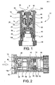
- the device 10 comprises a duct 12 for passage of a flow of liquid.
- the duct 12 for passage of liquid has an inlet passage 12a and an outlet passage 12b.
- Designated by F is the direction of flow of liquid in conditions of normal use of the apparatus downstream. Said direction defines also a longitudinal direction of the duct.
- the duct 12 preferably defines a calibrated external body with cylindrical longitudinal section.
- limiting means 14 inserted along the duct 12 and defining a section for passage of the liquid that decreases progressively as the flowrate of liquid increases, until closing of the duct occurs once a given threshold flowrate has been reached.
- the limiting means comprise at least one male element 18 and at least one female element 20, which are mobile with respect to one another so that they slide into one another as the flowrate of liquid increases so that progressive insertion into one another of the male element 18 and the female element 20 will define the section of passage.
- the male element 18 comprises at least one wedge 22 with cross section that increases in the longitudinal direction of the duct, in the opposite direction to the normal flow of liquid.
- the male element 18 comprises a plurality of wedges 22, arranged along an outer perimeter of the male element itself.
- the male element 18 is preferably obtained with a substantially axisymmetrical structure.
- the male element 18 has an axisymmetrical structure, and six wedges 22 are provided distributed along the outer circumference of the male element itself.
- the wedges 22 are shaped like a cone or have a semi-circular cross section.
- the female element 20 comprises at least one slot 24 suitable for receiving the respective wedge 22 of the male element 18.
- the slot 24 extends in the longitudinal direction of the duct 12 for passage of liquid.
- the slot 24 can present a constant cross section in the longitudinal direction of the duct 12.
- the at least one slot can be obtained as a recess made in the external surface of the female element 20, open in the direction of the internal walls of the duct 12 for passage of liquid.
- two or more slots 24 are provided, made in the external surface of the female element 20.
- the slot 24 has the shape of a circular sector.
- the external dimension (external diameter in the case of an axisymmetrical female element) of the female element 20 is slightly smaller than the minimum section defined by the duct 12 for passage of liquid.
- the female element 20 is made with an axisymmetrical structure.
- the female element 20 made with an axisymmetrical structure 20 comprises two or more slots 24 distributed along the external cylindrical surface of the female element itself.
- the male element 18 and the female element 20, with the corresponding elastic retention element set in between are partially inserted the former into the latter in a condition of dynamic balance that determines a free section 16 ( Figure 4 ) between each slot, the corresponding wedge, and the internal walls of the duct.
- the section of passage of liquid is defined by the sum of the free sections 16 defined between each slot 24, the corresponding wedge 22, and the internal wall of the duct 12 for passage of liquid in a given cross section of the limiting means 14, as is illustrated, for example, in Figure 4 and Figure 7 .
- the male element 18 and the female element 20 are shaped with respect to one another in such a way as to reduce the section of passage as the flowrate of liquid increases, with closing of the duct 12 as soon as a given threshold flowrate is reached.
- an elastic retention element 26 is set between the male element 18 and the female element 20 of the limiting means 14.
- both the male element 18 and the female element 20 define a corresponding seat for housing the elastic retention element.
- the elastic retention element is obtained by means of a helical spring.
- the anti-flooding device further comprises an anti-flooding open/close element 28, advantageously associated to the limiting means 14, and an anti-flooding seat 30, arranged along the duct 12 for passage of liquid.
- the anti-flooding open/close element 28 is made in such a way as to close the anti-flooding seat 30 under the action of the thrust exerted by the limiting means 14 once the threshold flowrate is exceeded.
- the anti-flooding open/close element 28 is associated to one between the male element 18 and female element 20, preferably by means of a stem 22 set longitudinally along the duct 12 for passage of liquid.
- the anti-flooding open/close element 28 is connected to the male element 18, which is thus mobile with respect to the female element 20, until the threshold flowrate is reached.
- the stem 32 traverses the female element 20 in the longitudinal direction.
- the anti-flooding open/close element 28 houses a gasket or O-ring 34 to ensure a better seal against the walls of the anti-flooding seat 30.
- the limiting means 14 and the anti-flooding open/close element 28 constitute a sort of cartridge that can be inserted in the duct 12 for passage of liquid.
- the anti-flooding device further comprises an anti-flooding elastic element 36, which acts so as to keep the anti-flooding seat 30 open during normal operation of the apparatus set downstream.
- the anti-flooding elastic element 36 is set between a portion of the duct 12 and the limiting means 14, preferably the female element 20 of the limiting means 14.
- the anti-flooding elastic element 36 is pre-loaded in a resting position or a position of normal operation of the apparatus set downstream.
- the anti-flooding elastic element 36 has a greater stiffness than the elastic retention element 26.
- the anti-flooding device further comprises a valve 38, associated to a downstream end of the duct 12 for passage of liquid and preferably defining the anti-flooding seat 30.
- the position of the valve can be adjustable along the duct 12, for example by means of a threaded coupling 4.
- the valve houses a gasket or O-ring 42 to ensure a better seal against the internal walls of the duct 12.
- the anti-flooding elastic element 36 is set between the limiting means 14 and the valve 38.
- the limiting means 14 comprise a retention open/close element 44.
- the duct 14 comprises a retention seat 46 set upstream with respect to the limiting means 14 with reference to the normal flow of liquid in such a way that the retention open/close element 44 is designed to close the retention seat 46 once the flow of liquid ceases.
- the retention open/close element 44 is connected, preferably by being made of a single piece therewith, to the male element 18 of the limiting means 14.
- the retention open/close element 44 houses a gasket or O-ring 48 to ensure a better seal against the walls of the retention seat 46.
- the anti-flooding open/close element 28 and the retention open/close element 44 are connected to one another preferably by means of the stem 32.
- the duct 12 for passage of liquid comprises means for engagement to a system, comprising, for example, threaded attachments or other joining means.
- the anti-flooding device according to the present invention can be used in a connection device 50 for a dispenser of drinking water or the like.
- the connection device will further comprise a pressure limiter 52.
- An example of such a connection device is illustrated in Figure 10 .
- the main function of the aforesaid device is the anti-flooding function, which enables immediate interruption of the flow of liquid, in particular water, in the case where the pipe for delivery to the final dispensing device slides out and/or undergoes failure.
- Figure 2 illustrates the initial condition of the anti-flooding device, in which the retention open/close element 44 is in contact with the retention seat 46.
- the elastic retention element 26 keeps the male element 18 and the female element 20 at a distance from one another.
- the elastic anti-flooding element 36 possibly pre-loaded, keeps the limiting means 14 and the anti-flooding open/close element 28 away from the anti-flooding seat 30.
- the male element 18 slightly approaches the female element 20, whilst its wedges insert into the respective slots.
- the water can flow through the slots 24 of the female element 20, which are only partially obstructed by the wedges 22 of the male element, in relative equilibrium.
- This partial obstruction is defined by a dynamic balance between the male element and the female element, which delimits a given free section 16 for each slot, in a region corresponding to a given cross section.
- the sum of the free sections determines the section of passage of the flow of liquid (water).
- Figure 3 illustrates the position of the device of Figure 2 during normal operation of the apparatus set downstream of the anti-flooding device, i.e., in the absence of failure or malfunctioning.
- both the retention seat 46 and the anti-flooding seat 30 are open, and the corresponding open/close elements are moved away from each seat in dynamic equilibrium as a result of the flow of liquid.
- the anti-flooding device is able to perform the supplementary function of retention and non-return preventing any reflux of the liquid in the case where there were any interruption in delivery.
- the retention open/close element 44 preferably associated to the male element 18 is pushed against the retention seat 46 by the hydrostatic pressure assumed by the water already delivered, i.e., downstream of the anti-flooding device and, for example, designated by the reference A in Figure 9 .
- the anti-flooding device according to the invention can provide also a non-return function to be carried out, thus preventing any reflux of liquid in the case of interruption in delivery.
- the wedges could have a constant cross section
- the slots could have a cross section that varies in the longitudinal direction of the duct in such a way as to obtain the effect of closing of the section of passage described previously, or else both the wedges and the slots can present a cross section that varies in the longitudinal direction of the duct.
Landscapes
- Engineering & Computer Science (AREA)
- General Engineering & Computer Science (AREA)
- Mechanical Engineering (AREA)
- Infusion, Injection, And Reservoir Apparatuses (AREA)
- Pipe Accessories (AREA)
- Developing Agents For Electrophotography (AREA)
- Electrical Discharge Machining, Electrochemical Machining, And Combined Machining (AREA)
- Paper (AREA)
- Safety Valves (AREA)
Applications Claiming Priority (1)
| Application Number | Priority Date | Filing Date | Title |
|---|---|---|---|
| IT000590A ITMI20080590A1 (it) | 2008-04-04 | 2008-04-04 | Dispositivo anti-allagamento |
Publications (2)
| Publication Number | Publication Date |
|---|---|
| EP2107283A2 true EP2107283A2 (fr) | 2009-10-07 |
| EP2107283A3 EP2107283A3 (fr) | 2012-01-04 |
Family
ID=40296855
Family Applications (1)
| Application Number | Title | Priority Date | Filing Date |
|---|---|---|---|
| EP20080013000 Withdrawn EP2107283A3 (fr) | 2008-04-04 | 2008-07-18 | Dispositif anti-écoulement |
Country Status (4)
| Country | Link |
|---|---|
| US (1) | US8353311B2 (fr) |
| EP (1) | EP2107283A3 (fr) |
| CN (1) | CN101551031B (fr) |
| IT (1) | ITMI20080590A1 (fr) |
Families Citing this family (11)
| Publication number | Priority date | Publication date | Assignee | Title |
|---|---|---|---|---|
| CN102787829B (zh) * | 2011-05-20 | 2015-03-25 | 大港油田集团有限责任公司 | 压裂与无泵采油一体化工艺管柱及其作业方法 |
| CN102494166B (zh) * | 2011-12-29 | 2013-03-27 | 珠海铂鸥卫浴用品有限公司 | 一种过流保护阀 |
| US9403410B2 (en) | 2013-02-11 | 2016-08-02 | Dana Heavy Vehicle Systems Group, Llc | System and method for decreasing tire pressure |
| US9415645B2 (en) | 2013-02-11 | 2016-08-16 | Dana Heavy Vehicle Systems Group, Llc | Valve assembly for a central tire inflation system |
| US9296264B2 (en) | 2013-02-11 | 2016-03-29 | Dana Heavy Vehicle Systems Group, Llc | System and method for decreasing tire pressure |
| US10259272B2 (en) | 2014-01-03 | 2019-04-16 | Dana Heavy Vehicle Systems Group, Llc | Assembly for a central tire inflation system |
| EP3160776A1 (fr) | 2014-06-30 | 2017-05-03 | Dana Heavy Vehicle Systems Group, LLC | Ensemble valve pour un système de gestion de pression de pneu |
| US10864783B2 (en) | 2016-01-29 | 2020-12-15 | Dana Heavy Vehicle Systems Group, Llc | Valve assembly for a tire inflation system |
| BR112018070694A2 (pt) * | 2016-04-13 | 2019-02-05 | Dana Heavy Vehicle Sys Group | conjunto de válvula para um sistema de gestão de pressão de pneus |
| US11473685B2 (en) * | 2019-01-15 | 2022-10-18 | Prevco Subsea Llc | Dual poppet pressure relief valve with vacuum adaptor capability |
| US12480589B2 (en) | 2019-01-15 | 2025-11-25 | Prevco Subsea Llc | Pressure relief valve assembly including series coupled valves and related methods |
Family Cites Families (13)
| Publication number | Priority date | Publication date | Assignee | Title |
|---|---|---|---|---|
| US383877A (en) * | 1888-06-05 | Pressure-regulator | ||
| US2357321A (en) * | 1941-05-16 | 1944-09-05 | Acrotorque Co | Control |
| US2526346A (en) * | 1945-12-12 | 1950-10-17 | Goldinger Robert Glenn | Accident valve |
| US2925826A (en) * | 1955-01-17 | 1960-02-23 | Dole Valve Co | Variable flow controller |
| US3122162A (en) * | 1963-06-20 | 1964-02-25 | Asa D Sands | Flow control device |
| US3326233A (en) * | 1964-04-30 | 1967-06-20 | John E Perruzzi | Bi-directional valve |
| US3438392A (en) * | 1967-05-19 | 1969-04-15 | Bastian Blessing Co | Multi-purpose liquid transfer valve |
| US4699166A (en) * | 1981-07-21 | 1987-10-13 | Harold Gold | Hydraulic fuse valve assembly |
| US5215113A (en) * | 1991-06-20 | 1993-06-01 | Terry Paul E | Precision safety shut-off valve |
| DE9421018U1 (de) * | 1994-01-04 | 1995-05-11 | Blaney, Trevor, London | Überlaufschutz |
| NL1011596C1 (nl) * | 1998-06-30 | 2000-01-04 | Watts Ocean B V | Debietbegrenzer. |
| US6988509B2 (en) * | 2003-03-17 | 2006-01-24 | Carleton Technologies, Inc. | Riser line shutoff valve |
| US7219690B2 (en) * | 2004-03-11 | 2007-05-22 | Watkins Manufacturing Corporation | Flow control valve |
-
2008
- 2008-04-04 IT IT000590A patent/ITMI20080590A1/it unknown
- 2008-07-18 EP EP20080013000 patent/EP2107283A3/fr not_active Withdrawn
- 2008-09-04 CN CN2008102134452A patent/CN101551031B/zh not_active Expired - Fee Related
- 2008-09-26 US US12/239,444 patent/US8353311B2/en not_active Expired - Fee Related
Also Published As
| Publication number | Publication date |
|---|---|
| CN101551031B (zh) | 2013-06-12 |
| US8353311B2 (en) | 2013-01-15 |
| EP2107283A3 (fr) | 2012-01-04 |
| ITMI20080590A1 (it) | 2009-10-05 |
| US20090250928A1 (en) | 2009-10-08 |
| CN101551031A (zh) | 2009-10-07 |
Similar Documents
| Publication | Publication Date | Title |
|---|---|---|
| US8353311B2 (en) | Anti-flooding device | |
| US8578962B2 (en) | Connection fitting | |
| US6543474B2 (en) | Pressure equalizing check valve | |
| FR2916511B1 (fr) | Dispositif de securite compact a declenchement automatique pour controler le debit d'un fluide. | |
| TW405068B (en) | Flow control valve assembly | |
| GB2509714A (en) | Plumbing diverter component | |
| US6063275A (en) | Reverse osmosis system having an accumulator means for preventing contamination of the system air gap | |
| MXPA02003013A (es) | Valvula automatica para estabilizar un dispositivo de mezclado termostatico. | |
| EP2058442A2 (fr) | Appareil de contrôle de l'écoulement de l'eau | |
| US20210017743A1 (en) | System and method for reusing the remnants of water in a hot-water pipeline with remote graphic interface | |
| EP3115660A1 (fr) | Unité de régulation d'écoulement ayant une fonction de limitation de l'angle d'inclinaison d'une pièce de régulation d'écoulement | |
| AU2010241371B2 (en) | Temperature Sensitive Relief Valve | |
| US7434595B2 (en) | Safety valve assembly having set and reset mechanisms | |
| US11772013B2 (en) | Tamper-proof single piece fluid sediment trap | |
| GB2311119A (en) | In-line temperature activated valve | |
| WO1991017382A1 (fr) | Dispositif de regulation de debit | |
| JP3782583B2 (ja) | 逆流防止弁の排水部集水構造 | |
| EP3418436A1 (fr) | Dispositif de tuyau et agencement | |
| JP6696275B2 (ja) | 貯湯式給湯機 | |
| DE19959941C2 (de) | Druckausdehnungsvorrichtung | |
| JPH074651Y2 (ja) | 定圧制御バルブ | |
| AU2018102096A4 (en) | Safety cut off hose | |
| KR200219467Y1 (ko) | 수압을 이용한 수돗물 토출량 조절장치 | |
| JP5260364B2 (ja) | 消火設備 | |
| WO2024074479A1 (fr) | Dispositif de régulation de débit pour réguler un écoulement de fluide à travers celui-ci |
Legal Events
| Date | Code | Title | Description |
|---|---|---|---|
| PUAI | Public reference made under article 153(3) epc to a published international application that has entered the european phase |
Free format text: ORIGINAL CODE: 0009012 |
|
| AK | Designated contracting states |
Kind code of ref document: A2 Designated state(s): AT BE BG CH CY CZ DE DK EE ES FI FR GB GR HR HU IE IS IT LI LT LU LV MC MT NL NO PL PT RO SE SI SK TR |
|
| AX | Request for extension of the european patent |
Extension state: AL BA MK RS |
|
| PUAL | Search report despatched |
Free format text: ORIGINAL CODE: 0009013 |
|
| AK | Designated contracting states |
Kind code of ref document: A3 Designated state(s): AT BE BG CH CY CZ DE DK EE ES FI FR GB GR HR HU IE IS IT LI LT LU LV MC MT NL NO PL PT RO SE SI SK TR |
|
| AX | Request for extension of the european patent |
Extension state: AL BA MK RS |
|
| RIC1 | Information provided on ipc code assigned before grant |
Ipc: F16K 17/30 20060101AFI20111125BHEP |
|
| 17P | Request for examination filed |
Effective date: 20120703 |
|
| AKX | Designation fees paid |
Designated state(s): AT BE BG CH CY CZ DE DK EE ES FI FR GB GR HR HU IE IS IT LI LT LU LV MC MT NL NO PL PT RO SE SI SK TR |
|
| AXX | Extension fees paid |
Extension state: AL Payment date: 20120704 Extension state: RS Payment date: 20120704 Extension state: MK Payment date: 20120704 Extension state: BA Payment date: 20120704 |
|
| STAA | Information on the status of an ep patent application or granted ep patent |
Free format text: STATUS: THE APPLICATION IS DEEMED TO BE WITHDRAWN |
|
| 18D | Application deemed to be withdrawn |
Effective date: 20150203 |