EP2107286A2 - Vanne de contrôle de vérification de réponse rapide - Google Patents
Vanne de contrôle de vérification de réponse rapide Download PDFInfo
- Publication number
- EP2107286A2 EP2107286A2 EP09155176A EP09155176A EP2107286A2 EP 2107286 A2 EP2107286 A2 EP 2107286A2 EP 09155176 A EP09155176 A EP 09155176A EP 09155176 A EP09155176 A EP 09155176A EP 2107286 A2 EP2107286 A2 EP 2107286A2
- Authority
- EP
- European Patent Office
- Prior art keywords
- valve
- rod
- valve element
- valve seat
- housing
- Prior art date
- Legal status (The legal status is an assumption and is not a legal conclusion. Google has not performed a legal analysis and makes no representation as to the accuracy of the status listed.)
- Pending
Links
Images
Classifications
-
- F—MECHANICAL ENGINEERING; LIGHTING; HEATING; WEAPONS; BLASTING
- F16—ENGINEERING ELEMENTS AND UNITS; GENERAL MEASURES FOR PRODUCING AND MAINTAINING EFFECTIVE FUNCTIONING OF MACHINES OR INSTALLATIONS; THERMAL INSULATION IN GENERAL
- F16K—VALVES; TAPS; COCKS; ACTUATING-FLOATS; DEVICES FOR VENTING OR AERATING
- F16K1/00—Lift valves or globe valves, i.e. cut-off apparatus with closure members having at least a component of their opening and closing motion perpendicular to the closing faces
- F16K1/32—Details
- F16K1/34—Cutting-off parts, e.g. valve members, seats
- F16K1/36—Valve members
-
- F—MECHANICAL ENGINEERING; LIGHTING; HEATING; WEAPONS; BLASTING
- F16—ENGINEERING ELEMENTS AND UNITS; GENERAL MEASURES FOR PRODUCING AND MAINTAINING EFFECTIVE FUNCTIONING OF MACHINES OR INSTALLATIONS; THERMAL INSULATION IN GENERAL
- F16K—VALVES; TAPS; COCKS; ACTUATING-FLOATS; DEVICES FOR VENTING OR AERATING
- F16K1/00—Lift valves or globe valves, i.e. cut-off apparatus with closure members having at least a component of their opening and closing motion perpendicular to the closing faces
- F16K1/32—Details
- F16K1/34—Cutting-off parts, e.g. valve members, seats
- F16K1/42—Valve seats
-
- F—MECHANICAL ENGINEERING; LIGHTING; HEATING; WEAPONS; BLASTING
- F16—ENGINEERING ELEMENTS AND UNITS; GENERAL MEASURES FOR PRODUCING AND MAINTAINING EFFECTIVE FUNCTIONING OF MACHINES OR INSTALLATIONS; THERMAL INSULATION IN GENERAL
- F16K—VALVES; TAPS; COCKS; ACTUATING-FLOATS; DEVICES FOR VENTING OR AERATING
- F16K15/00—Check valves
- F16K15/02—Check valves with guided rigid valve members
- F16K15/025—Check valves with guided rigid valve members the valve being loaded by a spring
- F16K15/026—Check valves with guided rigid valve members the valve being loaded by a spring the valve member being a movable body around which the medium flows when the valve is open
- F16K15/028—Check valves with guided rigid valve members the valve being loaded by a spring the valve member being a movable body around which the medium flows when the valve is open the valve member consisting only of a predominantly disc-shaped flat element
-
- F—MECHANICAL ENGINEERING; LIGHTING; HEATING; WEAPONS; BLASTING
- F16—ENGINEERING ELEMENTS AND UNITS; GENERAL MEASURES FOR PRODUCING AND MAINTAINING EFFECTIVE FUNCTIONING OF MACHINES OR INSTALLATIONS; THERMAL INSULATION IN GENERAL
- F16K—VALVES; TAPS; COCKS; ACTUATING-FLOATS; DEVICES FOR VENTING OR AERATING
- F16K25/00—Details relating to contact between valve members and seats
-
- F—MECHANICAL ENGINEERING; LIGHTING; HEATING; WEAPONS; BLASTING
- F16—ENGINEERING ELEMENTS AND UNITS; GENERAL MEASURES FOR PRODUCING AND MAINTAINING EFFECTIVE FUNCTIONING OF MACHINES OR INSTALLATIONS; THERMAL INSULATION IN GENERAL
- F16K—VALVES; TAPS; COCKS; ACTUATING-FLOATS; DEVICES FOR VENTING OR AERATING
- F16K31/00—Actuating devices; Operating means; Releasing devices
- F16K31/02—Actuating devices; Operating means; Releasing devices electric; magnetic
- F16K31/06—Actuating devices; Operating means; Releasing devices electric; magnetic using a magnet, e.g. diaphragm valves, cutting off by means of a liquid
- F16K31/0644—One-way valve
- F16K31/0655—Lift valves
Definitions
- the present invention relates generally to vehicle check valves.
- Electromechanical actuators are used in many vehicle applications to control fluid flow in vehicle systems such as anti-lock brake systems (ABS) and fuel injection systems.
- ABS anti-lock brake systems
- the pressure pulsations from a fuel pump that is driven by a belt or directly from an engine shaft can be controlled by one or more solenoid-operated check valves, the operation of which can be synchronized with a camshaft to deliver the required flow and pressure to fuel rail injectors.
- the valve plainly must operate very quickly.
- a variety of factors can complicate achieving proper valve operation under such trying conditions. Among these factors are friction, hydraulic stiction, misalignment, improper damping, inertia, and mass, to name a few.
- friction can complicate achieving proper valve operation under such trying conditions. Among these factors are friction, hydraulic stiction, misalignment, improper damping, inertia, and mass, to name a few.
- reducing hydraulic forces can enhance the ability of the valve to operate very quickly.
- the present invention recognizes that reducing hydraulic forces in many applications can have a beneficial cascading effect, e.g., a less-massive valve which has less inertia to resist quick response can be provided.
- a check valve has a valve housing slidably supporting an actuator rod.
- a hollow valve seat insert is disposed in the housing.
- the insert can be hardened but the housing need not be hardened.
- the insert defines a rod guide slidably receiving the rod and a lobe-shaped opening defining a valve seat.
- a valve element is juxtaposed with the valve seat for selectively blocking the opening.
- the valve element can be formed with at least three lobes, as can be the opening.
- the lobes can be contiguous to each other.
- the rod may be moved by actuating a coil.
- the rod can be urged against the valve element by a spring to distance the valve element from the valve seat when the coil is deenergized.
- the coil when energized moves the rod away from the valve element to allow fluid pressure to urge the valve element against the valve seat.
- a valve in another aspect, includes a valve housing slidably supporting an actuator rod, and a hollow lobe-shaped valve seat is in the housing. A valve element is juxtaposed with the valve seat for selectively blocking an opening circumscribed by the valve seat.
- an actuator in still another aspect, includes a valve housing slidably supporting an actuator rod.
- a valve seat is in the housing and circumscribes a non-round opening.
- a valve element is juxtaposed with the valve seat and a spring urges the rod toward the valve element in an open configuration.
- a coil is energizable to move the rod away from the valve element in a closed configuration.
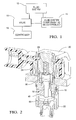
- Figure 1 is a block diagram of the present valve in one non-limiting environment
- Figure 2 is a partial cross-sectional view of one embodiment of the valve actuator assembly, with portions of the housing cut away for clarity;
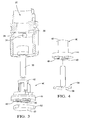
- Figure 3 is an exploded perspective view in partial cross-section of the lower portion of the assembly showing an embodiment of the valve element and valve seat insert in an exploded relationship with the remainder of the valving component enclosure of the housing, with portions of the housing cut away for clarity;
- Figure 4 is an exploded perspective view of a valve seat insert with alternate valve element.
- a valve 10 in accordance with present principles may be used in a vehicle system 12 such as vehicle fuel injection system having a fuel pump to control fluid flow such as fuel flow to a component 14 such as an injector rail of the system 12.
- the valve 10 can be controlled by a controller 16 such as an electro-mechanical control mechanism or a digital computer control mechanism such as an engine control module (ECM).
- ECM engine control module
- FIGS 2 and 3 show an example embodiment of the valve 10.
- the valve 10 can be formed with a hollow, typically metal housing 18 defining an electric component enclosure 20 and a valving component enclosure 22, with the enclosures 20, 22 being defined by the housing 18.
- the electric component enclosure 22 holds an electrical coil 24 which surrounds a plunger 26 that can reciprocate within the housing 18.
- a spring 28 in the electric component enclosure 22 urges against the plunger 26 as shown to urge the plunger 26 toward the valving component enclosure 22.
- An elongated rigid rod 30 is connected to or made integrally with the plunger 26, and the rod 30 extends into the valving component enclosure 22.
- the valving component enclosure 22 can define a radially enlarged axial channel 32 and, if desired and depending on the application, radially smaller radial fluid channels 34, 36 that may be perpendicular to each other and that may each lie in a horizontal plane that is perpendicular to the axial channel 32. Furthermore, the valving component enclosure 22 can be formed with an annular shoulder 38 that is perpendicular to the axial channel 32 as shown.
- a hollow rigid valve seat insert 40 is made separately from the housing 18 and is disposable in the axial channel 32 of the valving component enclosure 22.
- the insert 40 which can be press fit into the housing 18, preferably is metal that can be hardened using, e.g., precipitation/age hardening to improve its wear characteristics, while the housing 18, being relieved of some of its wear requirements by the insert 40, need not be hardened so as to optimize its magnetic characteristics.
- the example insert 40 defines an axially-oriented hollow rod guide 42 that slidably receives the rod 30.
- the walls of the rod guide 42 may be continuous or, as shown, may be defined by plural (e.g., three) axially-oriented wall portions, the inside surface of each of which defines a portion of a cylinder.
- the insert 40 defines a disk-shaped seat member 44, the upper surface of which abuts the shoulder 38 of the valving component enclosure 22 of the housing 18.
- a continuous axial passageway is formed by the rod guide 42, and the passageway terminates in an opening 46 of the seat member 44.
- the opening 46 is not round; in the specific example shown in Figure 3 , it is lobe-shaped, and is circumscribed by a complementarily-shaped valve seat 48.
- Three lobes are shown in Figure 3 , it being understood that when a lobe shape is used, more than three lobes may be provided.
- each lobe is configured as half of a racetrack, i.e., with two opposed co-parallel straight edges joined by an arcuate segment.
- valve element 50 that may be made of resilient plastic rubber is juxtaposed with the valve seat 48 for selectively blocking the opening 46 as shown.
- the valve element 50 may be generally disk-shaped, and in one non-limiting embodiment the valve element 50 may have plural (e.g., three) small protrusions 52 that may be thought of as "lobes" that are not contiguous to each other, i.e., the lobe-like protrusions 52 are separated from each other by arcuate segments of the periphery of the otherwise disk-shaped valve element 50.
- the present valve may incorporate a valve element 54 having plural lobes 56 that are contiguous to each other and that may match the lobes of the opening 46 of the insert 40.
- valve elements of the present invention may be flat as shown, and may also include structure to stabilize and align the valving portion during operation.
- the rod 30 is urged against the valve element 50/54 by the spring 28 to distance the valve element from the valve seat 48, allowing fluid flow through the opening 46.
- the coil 24 when energized moves the plunger 26 and, hence, rod 30 away from the valve element 50/54 to allow fluid pressure to urge the valve element against the valve seat 48, closing the opening 46.
Landscapes
- Engineering & Computer Science (AREA)
- General Engineering & Computer Science (AREA)
- Mechanical Engineering (AREA)
- Check Valves (AREA)
- Magnetically Actuated Valves (AREA)
Applications Claiming Priority (1)
| Application Number | Priority Date | Filing Date | Title |
|---|---|---|---|
| US12/080,458 US20090250643A1 (en) | 2008-04-03 | 2008-04-03 | Fast response check control valve |
Publications (2)
| Publication Number | Publication Date |
|---|---|
| EP2107286A2 true EP2107286A2 (fr) | 2009-10-07 |
| EP2107286A3 EP2107286A3 (fr) | 2009-10-28 |
Family
ID=40792487
Family Applications (1)
| Application Number | Title | Priority Date | Filing Date |
|---|---|---|---|
| EP09155176A Pending EP2107286A3 (fr) | 2008-04-03 | 2009-03-13 | Vanne de contrôle de vérification de réponse rapide |
Country Status (2)
| Country | Link |
|---|---|
| US (1) | US20090250643A1 (fr) |
| EP (1) | EP2107286A3 (fr) |
Cited By (1)
| Publication number | Priority date | Publication date | Assignee | Title |
|---|---|---|---|---|
| CN106051250A (zh) * | 2016-07-14 | 2016-10-26 | 郦强 | 一种防喘振阀装置 |
Family Cites Families (17)
| Publication number | Priority date | Publication date | Assignee | Title |
|---|---|---|---|---|
| FR574387A (fr) * | 1922-12-20 | 1924-07-10 | Nl Gist En Spiritusfabriek | Soupape en forme de robinet à deux ou plusieurs eaux, à commande de distribution électromagnétique |
| US3729025A (en) * | 1970-08-31 | 1973-04-24 | Bendix Corp | Solenoid valve with stroke insensitive port |
| GB2140129B (en) * | 1983-02-26 | 1986-04-09 | Lucas Ind Plc | Fluid control valves |
| GB8525059D0 (en) * | 1985-10-10 | 1985-11-13 | Boc Group Plc | Valves |
| US4825909A (en) * | 1988-02-24 | 1989-05-02 | Diesel Equipment Limited | High pressure hydraulic flow control valve |
| JPH03157576A (ja) * | 1989-11-15 | 1991-07-05 | Aisin Aw Co Ltd | 三方電磁弁及びその製造方法 |
| US5145146A (en) * | 1991-04-15 | 1992-09-08 | Yazaki Corporation | Nozzle support arrangement in electromagnetic valve |
| DE4221988A1 (de) * | 1992-07-04 | 1994-01-05 | Teves Gmbh Alfred | Elektromagnetventil |
| DE4426161C2 (de) * | 1994-07-22 | 1997-01-23 | Bosch Gmbh Robert | Magnetventil |
| DE4444910A1 (de) * | 1994-12-16 | 1996-06-27 | Binder Magnete | Magnetventil |
| US6026847A (en) * | 1995-10-11 | 2000-02-22 | Reinicke; Robert H. | Magnetostrictively actuated valve |
| US6065495A (en) * | 1999-02-04 | 2000-05-23 | General Motors Corporation | Two-position, three-way solenoid-actuated valve |
| DE10064357B4 (de) * | 2000-12-21 | 2005-08-04 | Danfoss A/S | Ventil, insbesondere Magnetventil |
| US6598852B2 (en) * | 2001-04-06 | 2003-07-29 | Keihin Corporation | Solenoid valve |
| DE10162604B4 (de) * | 2001-12-20 | 2004-02-26 | Danfoss A/S | Heizkörperventil |
| US7049916B2 (en) * | 2004-01-21 | 2006-05-23 | Keihin Corporation | Electromagnetic apparatus |
| JP2005325940A (ja) * | 2004-05-14 | 2005-11-24 | Smc Corp | 電磁弁 |
-
2008
- 2008-04-03 US US12/080,458 patent/US20090250643A1/en not_active Abandoned
-
2009
- 2009-03-13 EP EP09155176A patent/EP2107286A3/fr active Pending
Cited By (2)
| Publication number | Priority date | Publication date | Assignee | Title |
|---|---|---|---|---|
| CN106051250A (zh) * | 2016-07-14 | 2016-10-26 | 郦强 | 一种防喘振阀装置 |
| CN106051250B (zh) * | 2016-07-14 | 2019-04-05 | 苏州恩都法汽车系统有限公司 | 一种防喘振阀装置 |
Also Published As
| Publication number | Publication date |
|---|---|
| US20090250643A1 (en) | 2009-10-08 |
| EP2107286A3 (fr) | 2009-10-28 |
Similar Documents
| Publication | Publication Date | Title |
|---|---|---|
| JP4413260B2 (ja) | 高圧燃料ポンプ | |
| CN107709749B (zh) | 流量控制阀和高压燃料供给泵 | |
| EP3187725B1 (fr) | Pompe d'alimentation en carburant haute pression | |
| JP3151793B2 (ja) | ソレノイド作動流量制御弁アセンブリ | |
| US20100206252A1 (en) | High-pressure pump for a fuel system of an internal combustion engine | |
| EP3663571B1 (fr) | Pompe à carburant et ensemble soupape d'admission associée | |
| JP4569825B2 (ja) | 高圧燃料ポンプ | |
| KR102332033B1 (ko) | 연료 분사기 | |
| EP1944501B1 (fr) | Dispositif de valve électromagnétique et appareil d'injection de carburant doté du dispositif de valve | |
| EP1818584A2 (fr) | Vanne à solénoïde | |
| JPS62113862A (ja) | 電磁制御弁および内燃機関用燃料噴射装置 | |
| EP2852753B1 (fr) | Boîtier de soupape destiné à une soupape d'injection et soupape d'injection | |
| JP2013241835A (ja) | 高圧燃料ポンプのリリーフ弁 | |
| EP1302654A2 (fr) | Injecteur de carburant de moteur à combustion interne | |
| EP2410220A2 (fr) | Soupape de contrôle pour compresseur de déplacement variable | |
| US6158419A (en) | Control valve assembly for pumps and injectors | |
| EP2107286A2 (fr) | Vanne de contrôle de vérification de réponse rapide | |
| JP2009013937A (ja) | 高圧燃料ポンプ | |
| EP3267029B1 (fr) | Pompe à combustible dotée d'une soupape de pression maximum améliorée pour système à injection directe | |
| EP3156638A1 (fr) | Injecteur de carburant | |
| EP1093543B1 (fr) | Armature flexible pour clapet de regulation de systeme d'injection de carburant | |
| JP4332898B2 (ja) | 高圧燃料ポンプ | |
| JP5321982B2 (ja) | 高圧ポンプ | |
| US20180195481A1 (en) | Solenoid Valve for a Fuel Injection System, and High Pressure Fuel Pump | |
| EP2821632A1 (fr) | Soupape d'entrée numérique |
Legal Events
| Date | Code | Title | Description |
|---|---|---|---|
| PUAI | Public reference made under article 153(3) epc to a published international application that has entered the european phase |
Free format text: ORIGINAL CODE: 0009012 |
|
| STAA | Information on the status of an ep patent application or granted ep patent |
Free format text: STATUS: THE APPLICATION HAS BEEN PUBLISHED |
|
| PUAL | Search report despatched |
Free format text: ORIGINAL CODE: 0009013 |
|
| AK | Designated contracting states |
Kind code of ref document: A2 Designated state(s): AT BE BG CH CY CZ DE DK EE ES FI FR GB GR HR HU IE IS IT LI LT LU LV MC MK MT NL NO PL PT RO SE SI SK TR |
|
| AX | Request for extension of the european patent |
Extension state: AL BA RS |
|
| AK | Designated contracting states |
Kind code of ref document: A3 Designated state(s): AT BE BG CH CY CZ DE DK EE ES FI FR GB GR HR HU IE IS IT LI LT LU LV MC MK MT NL NO PL PT RO SE SI SK TR |
|
| AX | Request for extension of the european patent |
Extension state: AL BA RS |
|
| AKX | Designation fees paid | ||
| REG | Reference to a national code |
Ref country code: DE Ref legal event code: 8566 |